EP0231431B1 - Messwerterfassungseinrichtung - Google Patents
Messwerterfassungseinrichtung Download PDFInfo
- Publication number
- EP0231431B1 EP0231431B1 EP86112015A EP86112015A EP0231431B1 EP 0231431 B1 EP0231431 B1 EP 0231431B1 EP 86112015 A EP86112015 A EP 86112015A EP 86112015 A EP86112015 A EP 86112015A EP 0231431 B1 EP0231431 B1 EP 0231431B1
- Authority
- EP
- European Patent Office
- Prior art keywords
- measured value
- storage circuit
- value storage
- measured values
- recording
- Prior art date
- Legal status (The legal status is an assumption and is not a legal conclusion. Google has not performed a legal analysis and makes no representation as to the accuracy of the status listed.)
- Expired - Lifetime
Links
- 238000005259 measurement Methods 0.000 claims abstract description 6
- 238000010438 heat treatment Methods 0.000 claims abstract 6
- 230000001681 protective effect Effects 0.000 claims abstract 6
- 239000007858 starting material Substances 0.000 claims abstract 5
- 238000001514 detection method Methods 0.000 description 6
- 238000011156 evaluation Methods 0.000 description 2
- 238000003780 insertion Methods 0.000 description 2
- 230000037431 insertion Effects 0.000 description 2
- 239000002184 metal Substances 0.000 description 2
- 230000005611 electricity Effects 0.000 description 1
- 238000009434 installation Methods 0.000 description 1
- 239000011810 insulating material Substances 0.000 description 1
- 230000008054 signal transmission Effects 0.000 description 1
- XLYOFNOQVPJJNP-UHFFFAOYSA-N water Substances O XLYOFNOQVPJJNP-UHFFFAOYSA-N 0.000 description 1
Images


Classifications
-
- F—MECHANICAL ENGINEERING; LIGHTING; HEATING; WEAPONS; BLASTING
- F27—FURNACES; KILNS; OVENS; RETORTS
- F27D—DETAILS OR ACCESSORIES OF FURNACES, KILNS, OVENS OR RETORTS, IN SO FAR AS THEY ARE OF KINDS OCCURRING IN MORE THAN ONE KIND OF FURNACE
- F27D21/00—Arrangement of monitoring devices; Arrangement of safety devices
-
- F—MECHANICAL ENGINEERING; LIGHTING; HEATING; WEAPONS; BLASTING
- F27—FURNACES; KILNS; OVENS; RETORTS
- F27B—FURNACES, KILNS, OVENS OR RETORTS IN GENERAL; OPEN SINTERING OR LIKE APPARATUS
- F27B9/00—Furnaces through which the charge is moved mechanically, e.g. of tunnel type; Similar furnaces in which the charge moves by gravity
- F27B9/14—Furnaces through which the charge is moved mechanically, e.g. of tunnel type; Similar furnaces in which the charge moves by gravity characterised by the path of the charge during treatment; characterised by the means by which the charge is moved during treatment
- F27B9/20—Furnaces through which the charge is moved mechanically, e.g. of tunnel type; Similar furnaces in which the charge moves by gravity characterised by the path of the charge during treatment; characterised by the means by which the charge is moved during treatment the charge moving in a substantially straight path
- F27B9/26—Furnaces through which the charge is moved mechanically, e.g. of tunnel type; Similar furnaces in which the charge moves by gravity characterised by the path of the charge during treatment; characterised by the means by which the charge is moved during treatment the charge moving in a substantially straight path on or in trucks, sleds, or containers
- F27B9/262—Furnaces through which the charge is moved mechanically, e.g. of tunnel type; Similar furnaces in which the charge moves by gravity characterised by the path of the charge during treatment; characterised by the means by which the charge is moved during treatment the charge moving in a substantially straight path on or in trucks, sleds, or containers on or in trucks
-
- F—MECHANICAL ENGINEERING; LIGHTING; HEATING; WEAPONS; BLASTING
- F27—FURNACES; KILNS; OVENS; RETORTS
- F27D—DETAILS OR ACCESSORIES OF FURNACES, KILNS, OVENS OR RETORTS, IN SO FAR AS THEY ARE OF KINDS OCCURRING IN MORE THAN ONE KIND OF FURNACE
- F27D3/00—Charging; Discharging; Manipulation of charge
- F27D3/12—Travelling or movable supports or containers for the charge
- F27D3/123—Furnace cars
-
- G—PHYSICS
- G01—MEASURING; TESTING
- G01K—MEASURING TEMPERATURE; MEASURING QUANTITY OF HEAT; THERMALLY-SENSITIVE ELEMENTS NOT OTHERWISE PROVIDED FOR
- G01K13/00—Thermometers specially adapted for specific purposes
-
- G—PHYSICS
- G12—INSTRUMENT DETAILS
- G12B—CONSTRUCTIONAL DETAILS OF INSTRUMENTS, OR COMPARABLE DETAILS OF OTHER APPARATUS, NOT OTHERWISE PROVIDED FOR
- G12B17/00—Screening
- G12B17/06—Screening from heat
Definitions
- the invention relates to a measured value detection device on a continuous furnace car with a temperature protection vessel, in which a battery-operated measured value storage circuit is arranged, to which a plurality of sensors are connected, which are distributed outside the temperature protection vessel on the continuous furnace car.
- Such a measured value recording device is described in the literature reference Gas Marvel international, Volume 28 (1979), No. 6/7, pages 411 to 415.
- a measured value detection device for example, temperature profiles are recorded and stored, which occur at various points in the goods which are moved through the continuous furnace by means of the continuous furnace wagon.
- the measured value storage circuit is connected to an evaluation device which reads the stored measured values from the storage circuit.
- Such a measured value detection device eliminates the need for a trailing cable connection to a display station and high-frequency signal transmission from the furnace during the furnace journey.
- temperature protection vessel High demands are placed on the temperature protection vessel, since temperatures of over 1000 ° C can occur in the furnace and the temperature of the measured value storage circuit should not exceed about 70 ° C.
- temperature protection vessels are described in DE-PS 2 509 787 and DE-OS 2 825 111.
- a disadvantage of the known measured value recording devices is that they are switched on when they are attached to the continuous furnace car.
- the battery discharge and the acquisition of measured values begin at this early stage.
- this results in an unnecessary load on the battery and possibly an Storage of measurement values of no interest.
- the object of the invention is to propose a measured value recording device of the type mentioned at the outset, which can be started from the outside shortly before entering the continuous furnace.
- the above object is achieved in a measured value detection device of the type mentioned at the outset in that a switch-on circuit is arranged in the temperature protection vessel, which switches on the measured value storage circuit when a voltage is applied to its control input and that a control line is connected to the control input, the end of which is on the outside of the continuous furnace car.
- the measured value storage circuit is not yet activated after being installed on the continuous furnace car.
- the car can be loaded with the measured value memory circuit still switched off, the sensors being distributed in the desired areas.
- the loaded wagon can be parked for any length of time or driven through a dryer without the measured value storage circuit working. During this time, there is therefore neither battery consumption nor storage of measured values.
- Only when retracting the continuous furnace wagon in the tunnel oven is g at the Steuerleituri briefly a voltage set.
- the switch-on responds by the voltage pulse and switches on the measured value storage circuit.
- the battery therefore only needs to be designed in such a way that it is sufficient to supply power to the measured value storage circuit during the previously known duration of the furnace journey.
- the storage capacity of the measured value storage circuit can then also be designed in accordance with the measured values to be recorded during the furnace travel.
- thermocouples preferably thermocouples, pressure sensors, etc.
- pressure sensors preferably thermocouples, pressure sensors, etc.
- the switch-on circuit is designed such that it switches off the measured value storage circuit when a voltage is applied twice. This makes it possible to switch off the measured value storage circuit from the outside after the furnace trip has ended.
- a sheet metal container 2 is fastened to the bottom of a continuous furnace car 1.
- a water container surrounded by insulating material is arranged in this and has a cylindrical insertion chamber 3 which is open to the outside (cf. FIG. 2).
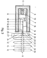
- a measured value acquisition unit 4 (cf. FIG. 3) is inserted into this.
- the measured value acquisition unit 4 has an outer jacket 5 and an inner jacket 6.
- a dewar 7 is arranged between the outer jacket 5 and the inner jacket 6.
- a terminal block 9 is attached to a flange 8, on which eight connection terminals 10 for temperature sensors and two further connection terminals 11 and 12 are arranged.
- a measured value storage circuit 13 is arranged in the inner jacket 6 and a battery B is provided for the power supply thereof.
- the measured value storage circuit 13 has a multiplexer MUX, which successively supplies the temperatures to the connecting terminals 10 via measured value lines 14 closed temperature sensors 1 z5.
- the multiplexer MUX is followed by an analog / digital converter A / D, which stores the digitized measured values in a memory RAM.
- a switch-on circuit 16 is arranged in the inner jacket 6 and has a relay 17 with a switching contact 18 in series with the battery B.
- the relay 17 is connected via lines 19 to the terminal 11.
- a line 20 located at one pole of the battery B and a line 21 located at the switch contact 18 are connected to the connection terminal 12.
- a control line 22 is connected to the connecting terminal 11 and is laid on the continuous furnace car 1 in such a way that its ends 23 end on the outside of the continuous furnace car 1 at an easily accessible location.
- a control line 24 is connected to the connecting terminals 12 and is laid next to the control line 22 so that its ends 25 are accessible next to the ends 23.
- the measured value acquisition unit 4 After assembly of the sheet metal container 2 on the continuous furnace car 1, the measured value acquisition unit 4 is inserted into the insertion chamber 3. The temperature sensors 15 are then attached to the intended measuring points and connected to the connecting terminals 10. The continuous furnace car 1 can then be loaded. The measured value storage circuit 13 is not yet working since the switch contact 18 is open.
- a battery 26 or another voltage source suitable for switching the relay 17 is briefly placed on the easily accessible ends 23. As a result, the relay 17 closes the switch contact 18, so that the measured value storage circuit 13 now operates. The battery 26 is then removed again. She does not take part in the kiln trip. A good thing about the switching of the relay 17 by the external battery 26 is that the relay 17 does not load the internal battery B.
- a light-emitting diode 27 can be placed briefly between the ends 25 of the control line 24. If it lights up, there is certainty that the measured value storage circuit 13 is operating.
- the battery 26 can be placed at the ends 23 again.
- the relay 17 opens the switch contact 18, so that the measured value storage circuit 13 is now switched off.
- the measured value acquisition unit 4 is dismantled and the memory RAM is connected to an evaluation circuit.
Landscapes
- Engineering & Computer Science (AREA)
- Mechanical Engineering (AREA)
- General Engineering & Computer Science (AREA)
- Physics & Mathematics (AREA)
- General Physics & Mathematics (AREA)
- Investigating Or Analyzing Materials By The Use Of Electric Means (AREA)
- Inspection Of Paper Currency And Valuable Securities (AREA)
- Indication And Recording Devices For Special Purposes And Tariff Metering Devices (AREA)
- Primary Cells (AREA)
- Waste-Gas Treatment And Other Accessory Devices For Furnaces (AREA)
Description
- Die Erfindung betrifft eine Meßwerterfassungseinrichtung an einem Durchlaufofenwagen mit einem Temperaturschutzgefäß, in dem eine batteriebetriebene Meßwertspeicherschaltung angeordnet ist, an die mehrere Meßfühler angeschlossen sind, welche außerhalb des Temperaturschutzgefäßes am Durchlaufofenwagen verteilt angeordnet sind.
- Eine derartige Meßwerterfassungseinrichtung ist in der Literaturstelle Gaswärme international, Band 28 (1979), Heft 6/7, Seiten 411 bis 415 beschrieben. Mit einer solchen Meßwerterfassungseinrichtung werden beispielsweise Temperaturverläufe erfaßt und gespeichert, die an verschiedenen Stellen des Gutes auftreten, das mittels des Durchlaufofenwagens durch den Durchlaufofen gefahren wird. Nach dem Abschluß der Ofenreise wird die Meßwertspeicherschaltung an eine Auswerteeinrichtung angeschlossen, die die gespeicherten Meßwerte aus der Speicherschaltung ausliest. Durch eine solche Meßwerterfassungseinrichtung erübrigt sich während der Ofenreise eine Schleppkabelverbindung zu einer Anzeigestation und eine hochfrequente Signalübertragung aus dem Ofen.
- An das Temperaturschutzgefäß werden hohe Anforderungen gestellt, da im Ofen Temperaturen über 1000°C auftreten können und die Temperatur der Meßwertspeicherschaltung etwa 70°C nicht übersteigen soll. Solche Temperaturschutzgefäße sind in der DE-PS 2 509 787 und in der DE-OS 2 825 111 beschrieben.
- Der in dem Temperaturschutzgefäß für die batteriebetriebene Meßwertspeicherschaltung zur Verfügung stehende Raum ist begrenzt. Es kann deshalb keine Batterie großer Leistung verwendet werden. Zur Stromersparnis ist in der DE-AS 2 308 887 vorgeschlagen, die Batterie nur in gewissen Meßtakten an die Meßwertspeicherschaltung anzuschalten.
- Nachteilig ist bei den bekannten Meßwerterfassungseinrichtungen, daß sie schon beim Anbau an den Durchlaufofenwagen eingeschaltet sind. Die Batterieentladung und die Meßwerterfassung beginnt schon in diesem frühen Zeitpunkt. Da in der Praxis zwischen der Montage der Meßwerterfassungseinrichtung am Durchlaufofenwagen und dessen Einfahrt in den Durchlaufofen eine lange Zeit verstreicht, die beispielsweise für die Beladung des Wagens und die Fahrt durch einen Trockner benötigt wird, ergibt sich eine an sich überflüssige Belastung der Batterie und gegebenenfalls eine Speicherung von nicht interessierenden Meßwerten.
- Aufgabe der Erfindung ist es, eine Meßwerterfassungseinrichtung der eingangs genannten Art vorzuschlagen, die sich von außen kurz vor der Einfahrt in den Durchlaufofen starten läßt.
- Erfindungsgemäß ist obige Aufgabe bei einer Meßwerterfassungseinrichtung der eingangs genannten Art dadurch gelöst, daß im Temperaturschutzgefäß eine Einschaltschaltung angeordnet ist, die bei einer an ihren Steuereingang angelegten Spannung die Meßwertspeicherschaltung einschaltet und daß an den Steuereingang eine Steuerleitung angeschlossen ist, deren Ende außen am Durchlaufofenwagen liegt.
- Die Meßwertespeicherschaltung ist dabei nach ihrer Montage am Durchlaufofenwagen noch nicht aktiviert. Der Wagen läßt sich bei noch abgeschalteter Meßwertspeicherschaltung beladen, wobei die Meßfühler in den gewünschten Bereichen verteilt werden. Der beladene Wagen läßt sich beliebig lange abstellen oder durch einen Trockner fahren, ohne daß die Meßwertspeicherschaltung arbeitet. Während dieser Zeit erfolgt also weder ein Batterieverbrauch noch eine Meßwertspeicherung. Erst beim Einfahren des Durchlaufofenwagens in den Durchlaufofen wird an die Steuerleiturig kurzzeitig eine Spannung gelegt. Durch den Spannungsimpuls spricht die Einschaltung an und schaltet die Meßwertspeicherschaltung ein. Die Batterie braucht also nur so ausgelegt zu werden, daß sie zur Stromversorgung der Meßwertspeicherschaltung während der vorher bekannten Dauer der Ofenreise ausreicht. Es kann dann auch die Speicherkapazität der Meßwertspeicherschaltung entsprechend der während der Ofenreise zu erfassenden Meßwerte ausgelegt werden.
- Ein weiterer Vorteil besteht in der Möglichkeit, gleichzeitig verschiedene Meßwertgeber, vorzugsweise Thermoelemente, Druckmeßsonden etc., in einem Gerät zu verwenden. Hierbei werden sowohl gleichzeitig unterschiedliche Meßbereiche als auch die gleichzeitige Messung verschiedener physikalischer Parameter ermöglicht.
- In bevorzugter Ausgestaltung der Erfindung ist die Einschaltschaltung so ausgelegt, daß sie bei einem zweitmaligen Anlegen einer Spannung die Meßwertspeicherschaltung abschaltet. Dadurch ist es möglich, die Meßwertspeicherschaltung nach Beendigung der Ofenreise von außen abzuschalten.
- Weitere vorteilhafte Ausgestaltungen der Erfindung ergeben sich aus den Unteransprüchen und der folgenden Beschreibung eines Ausführungsbeispiels. In der Zeichnung zeigen:
- Fig. 1 einen Durchlaufofenwagen mit einer Meßwerterfassungseinrichtung, schematisch,
- Fig. 2 einen Behälter für die Meßwerterfassungseinrichtung, und
- Fig. 3 die Meßwerterfassungseinrichtung, schematisch.
- Unten an einem Durchlaufofenwagen 1 ist ein Blechbehälter 2 befestigt. In diesem ist ein von Isoliermaterial umgebener Wasserbehälter angeordnet, der eine nach außen offene zylindrische Einsteckkammer 3 aufweist (vgl. Fig. 2). In diese ist eine Meßwerterfassungseinheit 4 (vgl. Fig. 3) eingeschoben.
- Die Meßwerterfassungseinheit 4 weist einen Außenmantel 5 und einen Innenmantel 6 auf. Zwischen dem Außenmantel 5 und dem Innenmantel 6 ist ein Dewar-Gefäß 7 angeordnet. An einem Flansch 8 ist eine Klemmenleiste 9 befestigt, an der acht Anschlußklemmen 10 für Temperaturfühler und zwei weitere Anschlußklemmen 11 und 12 angeordnet sind.
- Im Innenmantel 6 ist eine Meßwertspeicherschaltung 13 angeordnet, zu deren Stromversorgung eine Batterie B vorgesehen ist. Die Meßwertspeicherschaltung 13 weist einen Multiplexer MUX auf, der über Meßwertleitungen 14 im Takt nacheinander die Temperaturen an an die Anschlußklemmen 10 angeschlossenen Temperaturfühlern 1z5 abtastet. Dem Multiplexer MUX ist ein Analog/Digital-Wandler A/D nachgeschaltet, der die digitalisierten Meßwerte in einem Speicher RAM ablegt.
- In dem Innenmantel 6 ist eine Einschaltschaltung 16 angeordnet, die ein Relais 17 mit einem in Reihe zur Batterie B liegenden Schaltkontakt 18 aufweist. Das Relais 17 ist über Leitungen 19 an die Anschlußklemme 11 angeschlossen. Eine am einen Pol der Batterie B liegende Leitung 20 und eine am Schaltkontakt 18liegende Leitung 21 sind an die Anschlußklemme 12 geführt.
- An die Anschlußklemme 11 ist eine Steuerleitung 22 angeschlossen, die an dem Durchlaufofenwagen 1 so verlegt ist, daß ihre Enden 23 außen am Durchlaufofenwagen 1 an einer gut zugänglichen Stelle enden.
- An die Anschlußklemmen 12 ist eine Kontrolleitung 24 angeschlossen, die neben der Steuerleitung 22 verlegt ist, so daß ihre Enden 25 neben den Enden 23 zugänglich sind.
- Die Funktionsweise der beschriebenen Einrichtung ist etwa folgende:
- Nach der Montage des Blechbehälters 2 am Durchlaufofenwagen 1 wird die Meßwerterfassungseinheit 4 in die Einsteckkammer 3 eingesetzt. Anschließend werden die Temperaturfühler 15 an den vorgesehenen Meßstellen angebracht und mit den Anschlußklemmen 10 verbunden. Der Durchlaufofenwagen 1 läßt sich dann beladen. Die Meßwertspeicherschaltung 13 arbeitet noch nicht, da der Schaltkontakt 18 offen ist.
- Bevor der Durchlaufofenwagen 1 in den Durchlaufofen eingefahren ist, wird kurzzeitig eine Batterie 26 oder eine andere zum Schalten des Relais 17 geeignete Spannungsquelle an die gut zugänglichen Enden 23 gelegt. Dadurch schließt das Relais 17 den Schaltkontakt 18, so daß nunmehr die Meßwertspeicherschaltung 13 arbeitet. Die Batterie 26 wird dann wieder weggenommen. Sie macht die Ofenreise nicht mit. Günstig an dem Schalten des Relais 17 durch die externe Batterie 26 ist auch, daß das Relais 17 die interne Batterie B nicht belastet.
- Soll danach vor der Ofenreise kontrolliert werden, ob der Schaltkontakt 18 tatsächlich geschlossen ist, dann läßt sich kurzzeitig zwischen die Enden 25 der Kontrolleitung 24 eine Leuchtdiode 27 legen. Leuchtet sie auf, dann besteht Gewißheit, daß die Meßwertspeicherschaltung 13 arbeitet.
- Nach der Ofenreise kann erneut die Batterie 26 an die Enden 23 gelegt werden. Dadurch öffnet das Relais 17 den Schaltkontakt 18, so daß die Meßwertspeicherschaltung 13 jetzt abgeschaltet ist.
- Um die während der Ofenreise erfaßten Meßwerte auszuwerten, wird die Meßwerterfassungseinheit 4 demontiert und der Speicher RAM wird an eine Auswerteschaltung angeschlossen.
Claims (7)
Priority Applications (1)
| Application Number | Priority Date | Filing Date | Title |
|---|---|---|---|
| AT86112015T ATE49476T1 (de) | 1985-12-20 | 1986-08-29 | Messwerterfassungseinrichtung. |
Applications Claiming Priority (2)
| Application Number | Priority Date | Filing Date | Title |
|---|---|---|---|
| DE3545215 | 1985-12-20 | ||
| DE3545215A DE3545215C1 (de) | 1985-12-20 | 1985-12-20 | Messwerterfassungseinrichtung |
Publications (2)
| Publication Number | Publication Date |
|---|---|
| EP0231431A1 EP0231431A1 (de) | 1987-08-12 |
| EP0231431B1 true EP0231431B1 (de) | 1990-01-10 |
Family
ID=6289015
Family Applications (1)
| Application Number | Title | Priority Date | Filing Date |
|---|---|---|---|
| EP86112015A Expired - Lifetime EP0231431B1 (de) | 1985-12-20 | 1986-08-29 | Messwerterfassungseinrichtung |
Country Status (3)
| Country | Link |
|---|---|
| EP (1) | EP0231431B1 (de) |
| AT (1) | ATE49476T1 (de) |
| DE (2) | DE3545215C1 (de) |
Families Citing this family (5)
| Publication number | Priority date | Publication date | Assignee | Title |
|---|---|---|---|---|
| DE4022964C2 (de) * | 1990-07-19 | 1994-11-10 | Werner & Pfleiderer | Meßwerterfassungs- und Speichergerät für Feuchtigkeit und Temperatur |
| DE4219465C1 (de) * | 1992-06-13 | 1993-07-22 | Novokeram Max Wagner Gmbh, 8908 Krumbach, De | |
| GB0026580D0 (en) * | 2000-10-31 | 2000-12-13 | Datapaq Ltd | Insulation apparaus |
| DE102004056796A1 (de) * | 2004-11-24 | 2006-06-01 | Ebro Electronic Gmbh & Co. Kg | Vorrichtung zur Erfassung und Speicherung von Messwerten |
| DE102012112323B3 (de) * | 2012-12-14 | 2014-01-23 | Schott Ag | Temperatursensoranordnung zur zeitweisen Messung hoher Umgebungstemperaturen sowie deren Verwendung zur kabellosen Aufzeichnung eines Temperaturprofils bei der Glasherstellung oder Behandlung von Glaskörpern |
Family Cites Families (6)
| Publication number | Priority date | Publication date | Assignee | Title |
|---|---|---|---|---|
| FR2215134A5 (de) * | 1973-01-19 | 1974-08-19 | Intertechnique Sa | |
| DE2308887C3 (de) * | 1973-02-23 | 1985-08-08 | Atmos Fritzsching & Co Gmbh, Zweigniederlassung Lenzkirch Im Schwarzwald, 7825 Lenzkirch | Temperaturmeßverfahren und -einrichtung mit Speicherung der Meßwerte in einem temperaturisolierten Gefäß |
| DE2509787C2 (de) * | 1975-03-06 | 1982-06-16 | Hans Heinrich Prof. Dr.-Ing. 3300 Braunschweig Emschermann | Temperatur-Schutzgefäß für Meßeinrichtungen oder Teile von Meßeinrichtungen |
| US4160255A (en) * | 1976-10-04 | 1979-07-03 | Mitogiken, Ltd. | Recording apparatus with intermittent power usage |
| DE2720177C3 (de) * | 1977-05-05 | 1981-03-26 | C. Keller GmbH u. Co KG, 4530 Ibbenbüren | Vorrichtung zur Aufnahme eines Schalters, insbesondere Induktionsschalters |
| DE2825111A1 (de) * | 1978-06-08 | 1979-12-13 | Hans Heinrich Prof Emschermann | Temperatur-schutzgefaess |
-
1985
- 1985-12-20 DE DE3545215A patent/DE3545215C1/de not_active Expired
-
1986
- 1986-08-29 DE DE8686112015T patent/DE3668241D1/de not_active Revoked
- 1986-08-29 EP EP86112015A patent/EP0231431B1/de not_active Expired - Lifetime
- 1986-08-29 AT AT86112015T patent/ATE49476T1/de active
Also Published As
| Publication number | Publication date |
|---|---|
| DE3668241D1 (de) | 1990-02-15 |
| DE3545215C1 (de) | 1986-11-06 |
| ATE49476T1 (de) | 1990-01-15 |
| EP0231431A1 (de) | 1987-08-12 |
Similar Documents
| Publication | Publication Date | Title |
|---|---|---|
| EP0022450A1 (de) | Prüfverfahren für Gleichstromquellen wie Akkumulatoren und Prüfgerät dafür | |
| DE4123361C2 (de) | Akkumulatorenbatterie | |
| DE2610536B1 (de) | Verfahren zur feststellung des erhaltungs- und ladezustandes von blei- akkumulatoren sowie schaltungsanordnung zur durchfuehrung des verfahrens | |
| DE19542516C1 (de) | Temperatur-Sensor | |
| EP0447928A1 (de) | Verfahren und Batterieprüfgerät zum Bestimmen des Zustands einer Bleibatterie | |
| CH665908A5 (de) | Vorrichtung zum selektiven detektieren der gasfoermigen bestandteile von gasgemischen in luft mittels eines gassensors. | |
| DE2942494A1 (de) | Beheizbarer messfuehler fuer bestandteile von gasen, insbesondere in abgasen von brennkraftmaschinen | |
| DE2603772A1 (de) | In die wicklung eines fluessigkeitsgekuehlten transformators einfuehrbares thermometer | |
| DE2702432A1 (de) | Fuehler zum erfassen der sauerstoffkonzentration | |
| DE3545215C1 (de) | Messwerterfassungseinrichtung | |
| DE9313420U1 (de) | Tastkopf | |
| EP4115468B1 (de) | Vorrichtung sowie verfahren zur überwachung von nebeneinander angeordneten zellen | |
| DE2643903A1 (de) | Einrichtung an einer akkumulator- batterie | |
| DE2239549C3 (de) | Übertemperatur-Anzeige- und -Schutzvorrichtung, insbesondere in katalytisch wirkenden Abgasentgiftungsanlagen von Brennkraftmaschinen | |
| DE2931860A1 (de) | Heustock-temperaturmessonde fuer gleichzeitige temperaturmessung an verschiedenen stellen entlang der sonde | |
| DE102008030730A1 (de) | Verfahren und Vorrichtung zur Messung der Temperatur in einer Leitung oder einem Leitungsbündel und mit einer solchen Vorrichtung ausgerüstetes Fahrzeug | |
| DE4022964C2 (de) | Meßwerterfassungs- und Speichergerät für Feuchtigkeit und Temperatur | |
| DE2752290C2 (de) | Innengekühltes Hochspannungsenergiekabel | |
| WO2017167539A1 (de) | Verfahren und vorrichtung zum laden einer batterie | |
| EP0030387A2 (de) | Analoge Spannungsanzeige mit Flüssigkristallen | |
| DE3828525A1 (de) | Kraftstoffilter mit heizelement und integrierter leistungselektronik | |
| DE662719C (de) | Einrichtung zur UEberwachung von oberen und unteren Temperaturpunkten, insbesondere als Feuerschutz | |
| DE3431376C2 (de) | ||
| DE2553285C2 (de) | Überwachungsanordnung für die Lade- und Entladezyklen von Alkalimetall-Schwefel-Zellen und Verfahren zum Überwachen der Lade- und Entladezyklen von Alkalimetall-Schwefel-Zellen | |
| DE2056615A1 (de) | Isolationsüberwachungsvorrichtung |
Legal Events
| Date | Code | Title | Description |
|---|---|---|---|
| PUAI | Public reference made under article 153(3) epc to a published international application that has entered the european phase |
Free format text: ORIGINAL CODE: 0009012 |
|
| 17P | Request for examination filed |
Effective date: 19860911 |
|
| AK | Designated contracting states |
Kind code of ref document: A1 Designated state(s): AT BE CH DE FR GB IT LI LU NL SE |
|
| 17Q | First examination report despatched |
Effective date: 19890606 |
|
| GRAA | (expected) grant |
Free format text: ORIGINAL CODE: 0009210 |
|
| AK | Designated contracting states |
Kind code of ref document: B1 Designated state(s): AT BE CH DE FR GB IT LI LU NL SE |
|
| REF | Corresponds to: |
Ref document number: 49476 Country of ref document: AT Date of ref document: 19900115 Kind code of ref document: T |
|
| ITF | It: translation for a ep patent filed | ||
| REF | Corresponds to: |
Ref document number: 3668241 Country of ref document: DE Date of ref document: 19900215 |
|
| GBT | Gb: translation of ep patent filed (gb section 77(6)(a)/1977) | ||
| ET | Fr: translation filed | ||
| PGFP | Annual fee paid to national office [announced via postgrant information from national office to epo] |
Ref country code: DE Payment date: 19900811 Year of fee payment: 5 |
|
| PGFP | Annual fee paid to national office [announced via postgrant information from national office to epo] |
Ref country code: CH Payment date: 19900925 Year of fee payment: 5 |
|
| PGFP | Annual fee paid to national office [announced via postgrant information from national office to epo] |
Ref country code: BE Payment date: 19901005 Year of fee payment: 5 |
|
| PLBI | Opposition filed |
Free format text: ORIGINAL CODE: 0009260 |
|
| 26 | Opposition filed |
Opponent name: ULTRAKUST ELECTRONIC GMBH Effective date: 19901010 |
|
| NLR1 | Nl: opposition has been filed with the epo |
Opponent name: ULTRAKUST ELECTRONIC GMBH. |
|
| PGFP | Annual fee paid to national office [announced via postgrant information from national office to epo] |
Ref country code: GB Payment date: 19910805 Year of fee payment: 6 |
|
| PGFP | Annual fee paid to national office [announced via postgrant information from national office to epo] |
Ref country code: FR Payment date: 19910808 Year of fee payment: 6 Ref country code: AT Payment date: 19910808 Year of fee payment: 6 |
|
| PGFP | Annual fee paid to national office [announced via postgrant information from national office to epo] |
Ref country code: SE Payment date: 19910814 Year of fee payment: 6 |
|
| PGFP | Annual fee paid to national office [announced via postgrant information from national office to epo] |
Ref country code: LU Payment date: 19910828 Year of fee payment: 6 |
|
| ITTA | It: last paid annual fee | ||
| PG25 | Lapsed in a contracting state [announced via postgrant information from national office to epo] |
Ref country code: BE Effective date: 19910831 |
|
| PGFP | Annual fee paid to national office [announced via postgrant information from national office to epo] |
Ref country code: NL Payment date: 19910831 Year of fee payment: 6 |
|
| EPTA | Lu: last paid annual fee | ||
| BERE | Be: lapsed |
Owner name: DIDIER-WERKE A.G. Effective date: 19910831 |
|
| REG | Reference to a national code |
Ref country code: CH Ref legal event code: PL |
|
| RDAG | Patent revoked |
Free format text: ORIGINAL CODE: 0009271 |
|
| STAA | Information on the status of an ep patent application or granted ep patent |
Free format text: STATUS: PATENT REVOKED |
|
| 27W | Patent revoked |
Effective date: 19920214 |
|
| GBPR | Gb: patent revoked under art. 102 of the ep convention designating the uk as contracting state | ||
| NLR2 | Nl: decision of opposition | ||
| EUG | Se: european patent has lapsed |
Ref document number: 86112015.2 Effective date: 19920701 |