EP0231029B1 - Optical system - Google Patents
Optical system Download PDFInfo
- Publication number
- EP0231029B1 EP0231029B1 EP87101235A EP87101235A EP0231029B1 EP 0231029 B1 EP0231029 B1 EP 0231029B1 EP 87101235 A EP87101235 A EP 87101235A EP 87101235 A EP87101235 A EP 87101235A EP 0231029 B1 EP0231029 B1 EP 0231029B1
- Authority
- EP
- European Patent Office
- Prior art keywords
- optical system
- optical
- light source
- entrance
- optical axis
- Prior art date
- Legal status (The legal status is an assumption and is not a legal conclusion. Google has not performed a legal analysis and makes no representation as to the accuracy of the status listed.)
- Expired - Lifetime
Links
- 230000003287 optical effect Effects 0.000 title claims description 131
- 238000005286 illumination Methods 0.000 claims description 36
- 210000001747 pupil Anatomy 0.000 claims description 20
- 230000000007 visual effect Effects 0.000 claims 1
- 230000002093 peripheral effect Effects 0.000 description 13
- 230000004075 alteration Effects 0.000 description 6
- 230000010354 integration Effects 0.000 description 2
- 238000000034 method Methods 0.000 description 2
- NAWXUBYGYWOOIX-SFHVURJKSA-N (2s)-2-[[4-[2-(2,4-diaminoquinazolin-6-yl)ethyl]benzoyl]amino]-4-methylidenepentanedioic acid Chemical compound C1=CC2=NC(N)=NC(N)=C2C=C1CCC1=CC=C(C(=O)N[C@@H](CC(=C)C(O)=O)C(O)=O)C=C1 NAWXUBYGYWOOIX-SFHVURJKSA-N 0.000 description 1
- 238000004364 calculation method Methods 0.000 description 1
- 230000003247 decreasing effect Effects 0.000 description 1
- 238000012986 modification Methods 0.000 description 1
- 230000004048 modification Effects 0.000 description 1
- 238000004088 simulation Methods 0.000 description 1
Images


Classifications
-
- G—PHYSICS
- G02—OPTICS
- G02B—OPTICAL ELEMENTS, SYSTEMS OR APPARATUS
- G02B27/00—Optical systems or apparatus not provided for by any of the groups G02B1/00 - G02B26/00, G02B30/00
- G02B27/18—Optical systems or apparatus not provided for by any of the groups G02B1/00 - G02B26/00, G02B30/00 for optical projection, e.g. combination of mirror and condenser and objective
-
- G—PHYSICS
- G02—OPTICS
- G02B—OPTICAL ELEMENTS, SYSTEMS OR APPARATUS
- G02B3/00—Simple or compound lenses
- G02B3/02—Simple or compound lenses with non-spherical faces
- G02B3/04—Simple or compound lenses with non-spherical faces with continuous faces that are rotationally symmetrical but deviate from a true sphere, e.g. so called "aspheric" lenses
-
- G—PHYSICS
- G02—OPTICS
- G02B—OPTICAL ELEMENTS, SYSTEMS OR APPARATUS
- G02B19/00—Condensers, e.g. light collectors or similar non-imaging optics
-
- G—PHYSICS
- G02—OPTICS
- G02B—OPTICAL ELEMENTS, SYSTEMS OR APPARATUS
- G02B19/00—Condensers, e.g. light collectors or similar non-imaging optics
- G02B19/0004—Condensers, e.g. light collectors or similar non-imaging optics characterised by the optical means employed
- G02B19/0028—Condensers, e.g. light collectors or similar non-imaging optics characterised by the optical means employed refractive and reflective surfaces, e.g. non-imaging catadioptric systems
-
- G—PHYSICS
- G02—OPTICS
- G02B—OPTICAL ELEMENTS, SYSTEMS OR APPARATUS
- G02B19/00—Condensers, e.g. light collectors or similar non-imaging optics
- G02B19/0033—Condensers, e.g. light collectors or similar non-imaging optics characterised by the use
- G02B19/0047—Condensers, e.g. light collectors or similar non-imaging optics characterised by the use for use with a light source
Definitions
- the present invention relates generally to a novel optical system, and particularly to an optical system which provides light of excellent uniformity of intensity, without any illuminance reduction in the peripheral area of an object, so that it is particularly useful for an exposure system applicable to exposure of printed circuit boards, integrated circuits or the like, for an exposure system applicable to contact exposure apparatus for plate making, step-and-repeat machines or the like, and for an illumination system applicable to copy machines or the like.
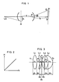
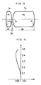
- the conventional condenser optical system comprises a condenser lens C and a field lens F.
- the condenser optical system is designed so that the real image of a light source LS, which is placed in front of the condenser lens C, is formed adjacent to the field lens F, and that the real image of an entrance pupil A of the condenser lens C is formed on an object S which is placed behind the field lens F.
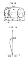
- the conventional condenser optical system raises a serious problem, i.e. the illuminance in the peripheral area of the object is reduced, as shown in Fig. 28, in accordance with the cosine fourth law.
- the illuminance at the point on the object, where the exit angle ⁇ forms 27 degrees relative to the optical system is less than that at the point on the optical axis, i.e. the point where the exit angle ⁇ forms zero degrees.
- Fig. 29 shows an illuminance distribution on the object S, which is obtained by using the optical system shown in Fig. 27, in the case where a point source is positioned on the optical axis at the distance of 50 from the optical system.
- Fig. 30 shows an illuminance distribution of the meridional ray on the object S
- Fig. 31 shows an illuminance distribution of the sagittal ray on the object S, in each of which the point source is positioned away by 14 from the optical axis and at a distance of 50 from the optical system.
- FIG. 29 through 31 depicts a relative illuminance, in which the illuminance of the center of the object S is regarded as 100 percent when the point source is positioned on the optical axis.
- the respective horizontal axis of Figs. 29 through 31 depicts a position on the object S.
- the position denoted by 50 in radius corresponds to the position on which the exit light from the optical system is impinged.
- the illuminance in the peripheral area of the object S is actually reduced less than a value derived from cosine fourth law.
- One of the reasons therefor is an aberration, because the cosine fourth law is on the premise that an optical system has no aberration, whereas an actual optical system inevitably has the aberration.
- an optical system is designed so that the aberration be eliminated as far as possible, in other words it has commonly been practiced that an optical system is designed so as to satisfy the sine condition.
- the optical system for use in illumination has conventionally been designed so as to satisfy the sine condition, because it has been believed as a matter of course by a person skilled in the art.
- Fig. 32 which is a schematic view of a typical optical system shown in Fig. 27, light emitted from the light source LS enters into the optical system at the entrance height h, in this case the light source LS can be regarded as being placed at an infinite distance from the optical system, because it is positioned at a far distance from the optical system in comparison with the focal length thereof.
- the relationship between the incident light radius A o around the optical axis of the entrance pupil A and the radius S o of the illumination area of the object S similarly to the relationship between the entrance height h and the illumination height H, is that the radius S o increases at a greater rate than the rate that the radius A o increases, from which it will be apparent that the illuminance on the object S will be reduced as it goes away from the optical axis, in comparison with that on the entrance pupil A.
- the present invention has the following useful advantages:
- the length of the optical path between the light source and the object can be extensively and effectively reduced, since the angular aperture is wide in the optical system according to the invention, whereas the wide range on the object can be evenly and uniformly illuminated thereby.
- the light entered into the optical system can be effectively used for illumination of the object, without any loss of light.
- the optical system is particularly useful for use in an illumination system of compact in size.
- Fig. 1 shows a schematic view of the optical system according to the invention
- light emitted from a light source LS which is positioned on the optical axis, enters into the optical system at the entrance height h, and in turn exits therefrom at the exit angle ⁇ , to illuminate the object S.
- the relationship between the radius A o around the optical axis, of the entrance pupil A, and the radius S o around it on the object S, within which the illumination is realized by the light entered through the radius A o is proportional similarly to the relationship between the entrance height h and the illumination height H. That is, when the value of the radius A o is increased, the value of the radius S o is increased at the same rate. From this, it will be apparent that the illuminance distribution on the object S is the same as that of the entrance pupil A, from the center to the peripheral area of the object.
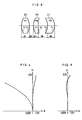
- the optical system shown therein comprises four optical units L1 to L4 including four lenses. Respective lens data of the optical system is listed in Table 2.
- Fig. 4 there are shown the characteristics of the proportional constant k relative to the entrance height h when using the optical system shown in Fig. 3, where the vertical axis depicts the entrance height h, and the horizontal axis depicts the proportional constant k, which is expressed in the formula (5).
- the characteristics of the proportional constant k relative to the entrance height h show the fidelity of the optical system to the ideal optical design of the present invention, from which the fact that the proportional constant k is constant independent of the entrance height h means that the optical system is designed to be ideal, i.e. the tangent of the exit angle ⁇ is exactly proportioned to the entrance height h.
- Fig. 4 the h-k characteristics of a conventional aplanatic lens are shown by a broken line for the purpose of comparison with the optical system shown in Fig. 3, from which it will be apparent that the optical system shown in Fig. 3 is very approximate to the ideal characteristics of the present invention, and that it is very different from the conventional aplanatic lens, because the fluctuation of the proportional constant k of the optical system shown in Fig. 3 is within the range of 0.008.
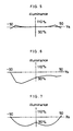
- Figs. 5 through 7 show an illuminance distribution on the object when using the optical system shown in Fig. 3, in which the object is placed at a distance of 100 from the optical system.
- Fig. 5 is a graphic representation of the illuminance distribution in the case where the point source is positioned on the optical axis at a distance of 50 from the front surface of the optical system
- Figs. 6 and 7 are graphic representations of the illuminance distribution of the meridional ray and the sagittal ray on the object, respectively, where the point source is positioned away by 14 from the optical axis and at a distance of 50 from the front surface of the optical system.
- the respective vertical axis of Figs. 5 through 7 depicts the relative illuminance when the illuminance of the center of the object is regarded as 100 percent.
- the optical system shown therein comprises three optical units L5 to L7 including three lenses.
- the lens data of the optical system is listed in Table 3.
- Fig. 9 there are shown the h-k characteristics of the optical system shown in Fig. 8.
- Figs. 10 through 12 respectively show an illuminance distribution on the object S when using the optical system, in which the object S is placed at a distance of 100 from the rear surface of the optical system.
- Fig. 10 is a graphic representation of the illuminance distribution in the case where the point source is positioned on the optical axis at a distance of 50 from the front surface of the optical system.
- Figs. 10 is a graphic representation of the illuminance distribution in the case where the point source is positioned on the optical axis at a distance of 50 from the front surface of the optical system.
- FIGS. 6 and 7 are graphic representations of the illuminance distribution on the meridional ray and the sagittal ray on the object respectively, in the case where the point source is positioned away by 14 from the optical axis and at a distance of 50 from the front surface of the optical system.
- the respective vertical axis of Figs. 10 through 12 depicts the relative illuminance when the illuminance of a distance of 50 from the front surface of the optical system.
- the respective vertical axis of Figs. 10 through 12 depicts the relative illuminance when the illuminance of the center of the object is regarded at 100 percent.
- the optical system shown therein comprises two optical units L8 to L9 including two lenses.
- Fig. 14 there are shown the h-k characteristics of the optical system shown in Fig. 13.
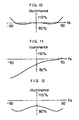
- Figs. 15 through 17 respectively shown an illuminance distribution on the object S when using the optical system, in which the object S is placed at a distance of 100 from the rear surface of the optical system.
- Fig. 15 is a graphic representation of the illuminance distribution in the case where the point source is positioned on the optical axis at an infinite distance from the front surface of the optical system.
- Figs. 16 and 17 are graphic representations of the illuminance distribution on the meridional ray and the sagittal ray on the object respectively, in the case where the incident rays from the point source are entered into the optical system at the incident angle of 10 degrees.
- the respective vertical axis of Figs. 15 through 17 depicts the relative illuminance when the illuminance of the center of the object is regarded as 100 percent.
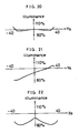
- the optical system shown therein comprises a single optical unit L10 including four lenses.
- the lens data of the optical system is listed in Table 5.
- Fig. 19 there are shown the h-k characteristics of the optical system shown in Fig. 18.
- Figs. 20 through 22 respectively show an illuminance distribution on the object S when using the optical system, in which the object is placed at a distance of 100 from the rear surface of the optical system.
- Fig. 20 is a graphic representation of the illuminance distribution in the case where the point source is positioned on the optical axis at a distance of 50 from the front surface of the optical system, and Figs.
- FIGS. 21 and 22 are graphic representations of the illuminance distribution of the meridional ray and the sagittal ray on the object respectively, in the case where the point source is positioned away by 14 from the optical axis and at a distance of 50 from the from the front surface of the optical system.
- the respective vertical axis of Figs. 20 through 22 depicts the relative illuminance when the illuminance of the center of the object is regarded as 100 percent.
- tan ⁇ h C (9) where h is an entrance height, and C is the distance between the entrance pupil A and the point P that the real image of the light source LS is formed.
- n1 denotes the refractive index of a prior medium to the surface of an aspherical lens
- n2 denotes the refractive index of a posterior medium thereto
- a symbol ⁇ denotes the angle at the incident point e of the light from the infinite distance, between the normal of the surface and the optical axis
- a symbol ⁇ denotes the angle which the light refracted at the surface forms relative to the optical axis.
- the integration constant C is expressed as the following formula (20):
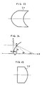
- the optical system shown therein comprises a single aspherical lens L11.
- the aspherical lens L11 is made of a material having a refractive index of 1.5.
- the prior medium to the lens L11 is an air, hence the refractive index thereof is 1.0.
- Z -1.5 ⁇ 1 + h2 ⁇ - 2.25log
- the front shape of the aspherical lens L11 is expressed by this formula, and the shape of the rear surface thereof is designed so as to satisfy the condition that the exit light is not refracted at the rear surface.
- the optical system shown therein comprises a single aspherical lens L12.
- the front surface of the aspherical lens L12 forms a plane
- the aspherical lens L12 is made of a material having a refractive index of 1.5.
- the rear surface thereof is designed as follows.
- the optical system according to the present invention can be designed as a fly-eye lens structure.
- the illumination system shown in Fig. 26 comprises a light source LS, an ellipsoidal mirror M, a fly-eye lens FE including a plurality of the optical systems as mentioned above and an object S.
- the fly-eye lens FE is designed so that respective optical axes of optical systems thereof run in parallel to each other, whereby a plurality of rays exited therefrom are impinged on the object S.
- the fly-eye lens structure is very useful for resolving the illuminance nonuniformity at the entrance pupil, which enables the object S to be illuminated uniformly independent of the illuminance distribution at the entrance pupil.
- respective optical system of the fly-eye lens provides uniform illumination through the entire area of the object, thus the illuminance distribution on the object will become very uniform.
- the relationship between the entrance pupil A and the object S is conjugate, because the light source inevitably has a dimension.
- the illumination system is designed so that the entrance pupil is conjugated with the object to be illuminated, light passing through a predetermined common point in the entrance pupil will impinge on a predetermined common point on the object, and accordingly light emitted from the light source and received in the entrance pupil will illuminate the predetermined area of the object, without any loss of light quantity.
Landscapes
- Physics & Mathematics (AREA)
- General Physics & Mathematics (AREA)
- Optics & Photonics (AREA)
- Lenses (AREA)
- Exposure And Positioning Against Photoresist Photosensitive Materials (AREA)
- Microscoopes, Condenser (AREA)
Applications Claiming Priority (2)
| Application Number | Priority Date | Filing Date | Title |
|---|---|---|---|
| JP61021049A JPS62178207A (ja) | 1986-01-31 | 1986-01-31 | 照明用の光学系 |
| JP21049/86 | 1986-01-31 |
Publications (3)
| Publication Number | Publication Date |
|---|---|
| EP0231029A2 EP0231029A2 (en) | 1987-08-05 |
| EP0231029A3 EP0231029A3 (en) | 1989-07-19 |
| EP0231029B1 true EP0231029B1 (en) | 1993-05-26 |
Family
ID=12044062
Family Applications (1)
| Application Number | Title | Priority Date | Filing Date |
|---|---|---|---|
| EP87101235A Expired - Lifetime EP0231029B1 (en) | 1986-01-31 | 1987-01-29 | Optical system |
Country Status (5)
| Country | Link |
|---|---|
| US (1) | US4852980A (enExample) |
| EP (1) | EP0231029B1 (enExample) |
| JP (1) | JPS62178207A (enExample) |
| KR (1) | KR910001503B1 (enExample) |
| DE (1) | DE3785938T2 (enExample) |
Families Citing this family (12)
| Publication number | Priority date | Publication date | Assignee | Title |
|---|---|---|---|---|
| JP2739712B2 (ja) * | 1986-05-14 | 1998-04-15 | キヤノン株式会社 | 照明光学系,焼付装置及び回路製造方法 |
| EP0299475B1 (en) * | 1987-07-17 | 1994-09-14 | Dainippon Screen Mfg. Co., Ltd. | Optical system for effecting increased irradiance in peripheral area of object |
| JPH0734057B2 (ja) * | 1987-08-07 | 1995-04-12 | 大日本スクリ−ン製造株式会社 | 照明用レンズ |
| US4953937A (en) * | 1988-05-17 | 1990-09-04 | Olympus Optical Co., Ltd. | Illumination optical system |
| JP2696360B2 (ja) * | 1988-10-28 | 1998-01-14 | 旭光学工業株式会社 | 照明光学装置 |
| US5485316A (en) * | 1991-10-25 | 1996-01-16 | Olympus Optical Co., Ltd. | Illumination optical system for endoscopes |
| GB9916715D0 (en) | 1999-07-19 | 1999-09-15 | Secr Defence | Compound lens arrangement for use in lens arrays |
| US7090357B2 (en) * | 2003-12-23 | 2006-08-15 | 3M Innovative Properties Company | Combined light source for projection display |
| US7300177B2 (en) * | 2004-02-11 | 2007-11-27 | 3M Innovative Properties | Illumination system having a plurality of light source modules disposed in an array with a non-radially symmetrical aperture |
| US7427146B2 (en) * | 2004-02-11 | 2008-09-23 | 3M Innovative Properties Company | Light-collecting illumination system |
| US7246923B2 (en) * | 2004-02-11 | 2007-07-24 | 3M Innovative Properties Company | Reshaping light source modules and illumination systems using the same |
| US7390097B2 (en) * | 2004-08-23 | 2008-06-24 | 3M Innovative Properties Company | Multiple channel illumination system |
Family Cites Families (8)
| Publication number | Priority date | Publication date | Assignee | Title |
|---|---|---|---|---|
| US3702395A (en) * | 1970-10-09 | 1972-11-07 | Us Navy | Condenser system for high intensity light source |
| DE2803277A1 (de) * | 1978-01-26 | 1979-08-02 | Bosch Gmbh Robert | Vorrichtung zur belichtung einer auf eine oberflaeche eines substrats aufgebrachten fotolackschicht |
| JPS5620428A (en) * | 1979-07-27 | 1981-02-26 | Olympus Optical Co | Lighting optical system for endoscope |
| JPS5759490Y2 (enExample) * | 1979-09-13 | 1982-12-18 | ||
| DD146213A1 (de) * | 1979-09-20 | 1981-01-28 | Pentacon K Veb | Zweiteiliges asphaerisches kondensorsystem |
| JPS56101116A (en) * | 1980-01-17 | 1981-08-13 | Minolta Camera Co Ltd | Fisheye lens |
| JPS5895706A (ja) * | 1981-12-02 | 1983-06-07 | Olympus Optical Co Ltd | 内視鏡用照明光学系 |
| EP0083394B1 (en) * | 1981-12-31 | 1986-04-09 | International Business Machines Corporation | A method and apparatus for providing a uniform illumination of an area |
-
1986
- 1986-01-31 JP JP61021049A patent/JPS62178207A/ja active Granted
-
1987
- 1987-01-16 US US07/003,957 patent/US4852980A/en not_active Expired - Fee Related
- 1987-01-27 KR KR1019870000633A patent/KR910001503B1/ko not_active Expired
- 1987-01-29 DE DE87101235T patent/DE3785938T2/de not_active Expired - Fee Related
- 1987-01-29 EP EP87101235A patent/EP0231029B1/en not_active Expired - Lifetime
Also Published As
| Publication number | Publication date |
|---|---|
| EP0231029A3 (en) | 1989-07-19 |
| KR910001503B1 (ko) | 1991-03-09 |
| DE3785938T2 (de) | 1994-01-05 |
| KR870007440A (ko) | 1987-08-19 |
| JPH0438322B2 (enExample) | 1992-06-24 |
| JPS62178207A (ja) | 1987-08-05 |
| US4852980A (en) | 1989-08-01 |
| EP0231029A2 (en) | 1987-08-05 |
| DE3785938D1 (de) | 1993-07-01 |
Similar Documents
| Publication | Publication Date | Title |
|---|---|---|
| EP0332201B1 (en) | Optical projection system | |
| US5900993A (en) | Lens systems for use in fingerprint detection | |
| US6958803B2 (en) | Projection exposure apparatus and method with adjustment of rotationally asymmetric optical characteristics | |
| EP0231029B1 (en) | Optical system | |
| US3909115A (en) | Lens with high resolving power but relatively small reduction ratio | |
| JP3608580B2 (ja) | 照明光学装置、露光装置、露光方法、及びフライアイレンズ | |
| US5696631A (en) | Unit magnification projection lens system | |
| Egger | Use of Fresnel lenses in optical systems: some advantages and limitations | |
| EP0299475B1 (en) | Optical system for effecting increased irradiance in peripheral area of object | |
| JPS63165837A (ja) | 高さを減少された透過性オーバーヘッド・プロジェクタ | |
| EP0587671B1 (en) | Condenser lens system for overhead projector | |
| US4492442A (en) | Three dimensional projection arrangement | |
| EP0059193B1 (en) | An optical system for projection | |
| JPS5512902A (en) | Unity-magnification copying lens having resolution power of refraction limit | |
| US5005959A (en) | Illumination system | |
| US3749477A (en) | Anamorphic lens system | |
| US3758196A (en) | Optical magnifying system and apparatus for viewing small objects | |
| US5390084A (en) | Illumination device | |
| US3572903A (en) | Spherically corrected fresnel lenses | |
| KR0141164B1 (ko) | 프로젝터용 투영광학계 | |
| JPS61123812A (ja) | 反射光学系 | |
| Bennett | Two simple calculating schemes for use in ophthalmic optics‐I. Tracing oblique rays through systems including astigmatic surfaces | |
| CN120161596A (zh) | 投影系统及照明装置 | |
| JP2720154B2 (ja) | 平行光照明用の照明装置 | |
| CN119846823A (zh) | 一种大像面大变倍比变焦光学镜头 |
Legal Events
| Date | Code | Title | Description |
|---|---|---|---|
| PUAI | Public reference made under article 153(3) epc to a published international application that has entered the european phase |
Free format text: ORIGINAL CODE: 0009012 |
|
| AK | Designated contracting states |
Kind code of ref document: A2 Designated state(s): DE FR GB IT |
|
| PUAL | Search report despatched |
Free format text: ORIGINAL CODE: 0009013 |
|
| 17P | Request for examination filed |
Effective date: 19890506 |
|
| AK | Designated contracting states |
Kind code of ref document: A3 Designated state(s): DE FR GB IT |
|
| 17Q | First examination report despatched |
Effective date: 19911205 |
|
| GRAA | (expected) grant |
Free format text: ORIGINAL CODE: 0009210 |
|
| AK | Designated contracting states |
Kind code of ref document: B1 Designated state(s): DE FR GB IT |
|
| PG25 | Lapsed in a contracting state [announced via postgrant information from national office to epo] |
Ref country code: IT Free format text: LAPSE BECAUSE OF FAILURE TO SUBMIT A TRANSLATION OF THE DESCRIPTION OR TO PAY THE FEE WITHIN THE PRESCRIBED TIME-LIMIT;WARNING: LAPSES OF ITALIAN PATENTS WITH EFFECTIVE DATE BEFORE 2007 MAY HAVE OCCURRED AT ANY TIME BEFORE 2007. THE CORRECT EFFECTIVE DATE MAY BE DIFFERENT FROM THE ONE RECORDED. Effective date: 19930526 Ref country code: FR Effective date: 19930526 |
|
| REF | Corresponds to: |
Ref document number: 3785938 Country of ref document: DE Date of ref document: 19930701 |
|
| EN | Fr: translation not filed | ||
| PLBE | No opposition filed within time limit |
Free format text: ORIGINAL CODE: 0009261 |
|
| STAA | Information on the status of an ep patent application or granted ep patent |
Free format text: STATUS: NO OPPOSITION FILED WITHIN TIME LIMIT |
|
| 26N | No opposition filed | ||
| PGFP | Annual fee paid to national office [announced via postgrant information from national office to epo] |
Ref country code: GB Payment date: 19980120 Year of fee payment: 12 |
|
| PGFP | Annual fee paid to national office [announced via postgrant information from national office to epo] |
Ref country code: DE Payment date: 19980206 Year of fee payment: 12 |
|
| PG25 | Lapsed in a contracting state [announced via postgrant information from national office to epo] |
Ref country code: GB Free format text: LAPSE BECAUSE OF NON-PAYMENT OF DUE FEES Effective date: 19990129 |
|
| GBPC | Gb: european patent ceased through non-payment of renewal fee |
Effective date: 19990129 |
|
| PG25 | Lapsed in a contracting state [announced via postgrant information from national office to epo] |
Ref country code: DE Free format text: LAPSE BECAUSE OF NON-PAYMENT OF DUE FEES Effective date: 19991103 |