EP0230791B1 - Detektor für voll gefüllten Resttonerbehälter - Google Patents
Detektor für voll gefüllten Resttonerbehälter Download PDFInfo
- Publication number
- EP0230791B1 EP0230791B1 EP86310200A EP86310200A EP0230791B1 EP 0230791 B1 EP0230791 B1 EP 0230791B1 EP 86310200 A EP86310200 A EP 86310200A EP 86310200 A EP86310200 A EP 86310200A EP 0230791 B1 EP0230791 B1 EP 0230791B1
- Authority
- EP
- European Patent Office
- Prior art keywords
- shutter
- waste toner
- image
- receptacle
- piston
- Prior art date
- Legal status (The legal status is an assumption and is not a legal conclusion. Google has not performed a legal analysis and makes no representation as to the accuracy of the status listed.)
- Expired
Links
- 239000002699 waste material Substances 0.000 title description 30
- 239000000463 material Substances 0.000 claims description 8
- 230000003287 optical effect Effects 0.000 claims description 5
- 238000006073 displacement reaction Methods 0.000 claims description 2
- 108091008695 photoreceptors Proteins 0.000 description 9
- 238000001514 detection method Methods 0.000 description 3
- 238000010276 construction Methods 0.000 description 2
- 238000000034 method Methods 0.000 description 1
- 238000012986 modification Methods 0.000 description 1
- 230000004048 modification Effects 0.000 description 1
- 238000007790 scraping Methods 0.000 description 1
Images

Classifications
-
- G—PHYSICS
- G03—PHOTOGRAPHY; CINEMATOGRAPHY; ANALOGOUS TECHNIQUES USING WAVES OTHER THAN OPTICAL WAVES; ELECTROGRAPHY; HOLOGRAPHY
- G03G—ELECTROGRAPHY; ELECTROPHOTOGRAPHY; MAGNETOGRAPHY
- G03G21/00—Arrangements not provided for by groups G03G13/00 - G03G19/00, e.g. cleaning, elimination of residual charge
- G03G21/10—Collecting or recycling waste developer
- G03G21/12—Toner waste containers
-
- G—PHYSICS
- G03—PHOTOGRAPHY; CINEMATOGRAPHY; ANALOGOUS TECHNIQUES USING WAVES OTHER THAN OPTICAL WAVES; ELECTROGRAPHY; HOLOGRAPHY
- G03G—ELECTROGRAPHY; ELECTROPHOTOGRAPHY; MAGNETOGRAPHY
- G03G15/00—Apparatus for electrographic processes using a charge pattern
- G03G15/04—Apparatus for electrographic processes using a charge pattern for exposing, i.e. imagewise exposure by optically projecting the original image on a photoconductive recording material
-
- G—PHYSICS
- G03—PHOTOGRAPHY; CINEMATOGRAPHY; ANALOGOUS TECHNIQUES USING WAVES OTHER THAN OPTICAL WAVES; ELECTROGRAPHY; HOLOGRAPHY
- G03G—ELECTROGRAPHY; ELECTROPHOTOGRAPHY; MAGNETOGRAPHY
- G03G15/00—Apparatus for electrographic processes using a charge pattern
- G03G15/14—Apparatus for electrographic processes using a charge pattern for transferring a pattern to a second base
- G03G15/16—Apparatus for electrographic processes using a charge pattern for transferring a pattern to a second base of a toner pattern, e.g. a powder pattern, e.g. magnetic transfer
- G03G15/163—Apparatus for electrographic processes using a charge pattern for transferring a pattern to a second base of a toner pattern, e.g. a powder pattern, e.g. magnetic transfer using the force produced by an electrostatic transfer field formed between the second base and the electrographic recording member, e.g. transfer through an air gap
- G03G15/1635—Apparatus for electrographic processes using a charge pattern for transferring a pattern to a second base of a toner pattern, e.g. a powder pattern, e.g. magnetic transfer using the force produced by an electrostatic transfer field formed between the second base and the electrographic recording member, e.g. transfer through an air gap the field being produced by laying down an electrostatic charge behind the base or the recording member, e.g. by a corona device
-
- G—PHYSICS
- G03—PHOTOGRAPHY; CINEMATOGRAPHY; ANALOGOUS TECHNIQUES USING WAVES OTHER THAN OPTICAL WAVES; ELECTROGRAPHY; HOLOGRAPHY
- G03G—ELECTROGRAPHY; ELECTROPHOTOGRAPHY; MAGNETOGRAPHY
- G03G15/00—Apparatus for electrographic processes using a charge pattern
- G03G15/04—Apparatus for electrographic processes using a charge pattern for exposing, i.e. imagewise exposure by optically projecting the original image on a photoconductive recording material
- G03G15/043—Apparatus for electrographic processes using a charge pattern for exposing, i.e. imagewise exposure by optically projecting the original image on a photoconductive recording material with means for controlling illumination or exposure
- G03G15/0435—Apparatus for electrographic processes using a charge pattern for exposing, i.e. imagewise exposure by optically projecting the original image on a photoconductive recording material with means for controlling illumination or exposure by introducing an optical element in the optical path, e.g. a filter
Definitions
- the present invention relates to an excess developer detector which detects when a developer container is full of waste developer collected from an image-bearing member in an electrographic image-recording apparatus.
- a full waste toner container is detected by a weight sensor, a pressure sensor or an optical sensor provided in the waste toner container. Since the volume and weight of waste toner tend to vary depending upon the waste toner density, however, detection by the weight or pressure sensor is not accurate. Detection by the optical sensor can be also inaccurate when the sensing surface of the sensor is soiled. In addition, the full waste toner container detector using any one of the above sensors incurs high cost.
- an assembly for the collection of excess developer material from an image-bearing member in an electrographic image-recording apparatus comprising a receptacle for receiving said excess material, a displaceable element arranged to be pushed by the material accumulating in said receptacle and an optical shutter and means for actuating said shutter so as to interrupt light projected onto said image-bearing member in response to displacement of said element.
- Such an arrangement provides for easy and accurate detection of a full receptacle, and the provision of a shutter for interrupting light projected onto the image-bearing member prevents an image from being copied when the receptacle is full of waste developer.
- the element is preferably a piston slidably disposed within a cylindrical projection formed in a wall of the receptacle, the piston having a head exposed to contact with material in the receptacle.
- the actuating means preferably comprises a wire connected between the piston and the shutter, in which case a biasing spring is preferably connected to the shutter at the point of connection of the wire thereto.
- the assembly is preferably integrally assembled with the image-bearing member as a cartridge which is removable from the body of the electrographic image-recording apparatus.
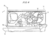
- FIG. 4 is a schematic construction drawing of a copying machine related to the present invention.
- a photoreceptor 1 is mounted, integrally with surrounding electric charger 2, cleaner unit 3, separator unit 4 and light exposure opening (slit) 5, in a housing 6, thus forming a cartridge 7.
- the cartridge 7 is detachable from the copying machine proper 8.
- the cartridge 7 can be set in the copying machine proper 8 simply by opening the front panel of the copying machine proper 8 and inserting the cartridge 7 vertical to a copy paper.
- the cartridge 7 can be dismounted by pulling it to the operator side.
- a rail guide mechanism (not shown) assists in mounting or dismounting the cartridge 7 in or from the copying machine proper 8.
- a convergent light transmitter 9 mounted over the light exposure slit 5 and a light source 10 provided to the left of the transmitter 9 constitute an optical system.
- a document on a manuscript rest 11 is scanned by a light beam from the light source 10 while the manuscript rest 11 is moving horizontally.
- the light reflected by the document surface passes through the convergent light transmitter 9 for projection onto the photoreceptor 1 which is rotating in the direction of the arrow of Fig. 4.
- the photoreceptor 1 is uniformly charged by the electric charger 2 before it is exposed to the light coming through the light exposure slit 5.
- An image is developed by a developing unit 12 and transferred onto a copy paper by a transference charger 13.
- the copy paper is fed from a copy paper cassette 14 by a paper feed roller 15 mounted at the bottom of the copying machine proper 8.
- the copy paper, on which the image has been transferred from the photoreceptor 1, is separated from the photoreceptor 1 by the separator unit 4 and conveyed to fixing rollers 16 where the image is fixed on the copy paper. Then, the copy paper is discharged onto a tray 17 which is rotatable about a pin 18 in the direction of the arrow of Fig. 4. For copying operation, the tray 17 which is folded as shown is rotated counterclockwise around the pin 18 and set in the position virtually parallel to the copying machine proper 8.
- the developing unit 12 has two developing sections either of which is selected by rotation.
- a shutter 20 is rotatably held by a shutter support plate 19 in the light path between the light exposure slit 5 and the convergent light transmitter 9.
- an end of a wire and a spring are connected to the shutter 20.
- the wire receiving tension proportional to the waste toner pressure in the container, gives rotation torque to the shutter 20 against the force of the spring.
- the shutter 20 rotates suddenly, closing the light path between the light exposure slit 5 and the convergent light transmitter 9.
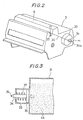
- Fig. 1 is a sectional view of the cartridge 7.
- the rotary shaft of the photoreceptor 1, the electric charger 2, the cleaner unit 3 and the separator unit 4 are mounted in the housing 6.
- the housing 6 has an opening at a portion facing the exposed area "A" of the photoreceptor 1, which opening defines the light exposure slit 5.
- the shutter support plate 19 is provided above the light exposure slit 5 and supports the shutter 20 to be rotatable.
- the spring 21 is connected between the housing 6 and an end of the shutter 20. An end of wire is also engaged with the shutter 20 as described later.
- the cleaner unit 3 comprises a blade 30 for scraping off the toner remaining on the photoreceptor 1 as waste toner, the waste toner container 31, and a rotary plate 32 which rotates to direct the waste toner to the waste toner container 31.
- Fig. 2 is a perspective view of the rear of the cartridge 7.
- the cleaner unit 3 has a projection 33 in its rear end.
- the projection 33 has a center hole through which a piston 34 is passed.
- the piston 34 is tapered in its end portion and has a groove 34a in the end.
- the wire 35 is slidably supported in the groove 34a, with an end connected to the point P1 of the housing 6 and the other end to the point P2.
- the point P2 engaged with the other end of the wire 35 is located in the upper part of the shutter 20 and conforms to the point to which the spring 20 is connected.
- Fig. 3 shows the section of the projection 33.
- the piston 34 is mounted on a slide 36 slidable in the projection 33.
- a spring 37 is provided between the slide 36 and the inner wall of the projection 33.
- the opposite side of the slide 36 is positioned to be in contact with the waste toner 22 in the container 31.
- the waste toner pressure in the container 31 increases, the waste toner pressure is applied in the direction of the arrow of Fig. 3 to the slide 36, causing the slide 36 to move toward the left against the force of the spring 37. Operation of the full waste toner container detector is described now.
- the waste toner pressure is applied in the direction of the arrow of Fig. 3 to the slide 36 according as the amount of the waste toner 22 and therefore its pressure increase.
- the spring 21 is connected to the shutter 20, permitting the shutter 20 to close the light path suddenly under the specified condition.
- the assembly according to the invention may not include the spring 21.
- the piston 34, wire 35 and shutter 20 are integrally mounted in the cartridge 7, when the shutter 20 has closed the light path "L" due to the full waste toner container, the only thing to be done is to replace the cartridge 7 with a new one; the replacement operation is easy enough to be carried out by the user without any help of service staff.
- the present invention since the piston moves responsive to the waste toner pressure in the container, it never happens that the detector determines the container is full when it is not or vice versa.
- the shutter closes the light path when the waste toner pressure in the container increases to a specified level, that is, when the container has been filled up with waste toner to a certain extent.
- the asembly of the present invention inhibits further image forming process when the container has been filled up, preventing waste toner from flowing over the container and soiling the interior of the image forming apparatus.
Landscapes
- Physics & Mathematics (AREA)
- General Physics & Mathematics (AREA)
- Life Sciences & Earth Sciences (AREA)
- Engineering & Computer Science (AREA)
- Environmental & Geological Engineering (AREA)
- Sustainable Development (AREA)
- Cleaning In Electrography (AREA)
Claims (5)
Applications Claiming Priority (2)
| Application Number | Priority Date | Filing Date | Title |
|---|---|---|---|
| JP60297301A JPS62153992A (ja) | 1985-12-27 | 1985-12-27 | 廃トナ−満杯検出装置 |
| JP297301/85 | 1985-12-27 |
Publications (2)
| Publication Number | Publication Date |
|---|---|
| EP0230791A1 EP0230791A1 (de) | 1987-08-05 |
| EP0230791B1 true EP0230791B1 (de) | 1991-04-10 |
Family
ID=17844736
Family Applications (1)
| Application Number | Title | Priority Date | Filing Date |
|---|---|---|---|
| EP86310200A Expired EP0230791B1 (de) | 1985-12-27 | 1986-12-29 | Detektor für voll gefüllten Resttonerbehälter |
Country Status (5)
| Country | Link |
|---|---|
| US (1) | US4750015A (de) |
| EP (1) | EP0230791B1 (de) |
| JP (1) | JPS62153992A (de) |
| CN (1) | CN1008011B (de) |
| DE (1) | DE3678703D1 (de) |
Families Citing this family (11)
| Publication number | Priority date | Publication date | Assignee | Title |
|---|---|---|---|---|
| USD303543S (en) | 1986-06-24 | 1989-09-19 | Canon Kabushiki Kaisha | Developing device for copying machine |
| JPH01136958U (de) * | 1988-03-15 | 1989-09-19 | ||
| US5079592A (en) * | 1989-06-02 | 1992-01-07 | Eastman Kodak Company | Cleaning system for electrophotographic apparatus |
| US5309202A (en) * | 1990-07-26 | 1994-05-03 | Konica Corporation | Image forming apparatus |
| JPH04237079A (ja) * | 1991-01-21 | 1992-08-25 | Ricoh Co Ltd | 現像装置 |
| JP2630689B2 (ja) * | 1991-05-20 | 1997-07-16 | シャープ株式会社 | 画像形成装置 |
| US5899597A (en) * | 1993-12-22 | 1999-05-04 | Ricoh Company Ltd. | Toner cartridge with an external reflector for a developer apparatus capable of optically end-detecting |
| US5621221A (en) * | 1993-12-22 | 1997-04-15 | Ricoh Company, Ltd. | Toner end detection device and method |
| JP3244992B2 (ja) * | 1994-03-15 | 2002-01-07 | キヤノン株式会社 | 電子写真画像形成装置 |
| CN108627216B (zh) * | 2018-05-11 | 2020-05-22 | 华北水利水电大学 | 一种水泥仓物料实时监测装置及监测方法 |
| EP4338012A4 (de) * | 2021-07-09 | 2024-07-24 | Hewlett-Packard Development Company, L.P. | Tonerübertragungsmodulatoren |
Family Cites Families (3)
| Publication number | Priority date | Publication date | Assignee | Title |
|---|---|---|---|---|
| EP0033647B1 (de) * | 1980-01-31 | 1985-08-21 | Mita Industrial Co. Ltd. | Reinigungsvorrichtung für ein elektrostatisches Kopiergerät |
| US4501484A (en) * | 1981-08-19 | 1985-02-26 | Ricoh Company, Ltd. | Photoconductive element cleaning apparatus and residual toner collecting apparatus |
| JPS60200277A (ja) * | 1984-03-23 | 1985-10-09 | Ricoh Co Ltd | 複写機のトナ−回収装置 |
-
1985
- 1985-12-27 JP JP60297301A patent/JPS62153992A/ja active Pending
-
1986
- 1986-12-23 US US06/945,517 patent/US4750015A/en not_active Expired - Lifetime
- 1986-12-24 CN CN86108833A patent/CN1008011B/zh not_active Expired
- 1986-12-29 DE DE8686310200T patent/DE3678703D1/de not_active Expired - Lifetime
- 1986-12-29 EP EP86310200A patent/EP0230791B1/de not_active Expired
Also Published As
| Publication number | Publication date |
|---|---|
| US4750015A (en) | 1988-06-07 |
| DE3678703D1 (de) | 1991-05-16 |
| JPS62153992A (ja) | 1987-07-08 |
| CN86108833A (zh) | 1987-07-01 |
| EP0230791A1 (de) | 1987-08-05 |
| CN1008011B (zh) | 1990-05-16 |
Similar Documents
| Publication | Publication Date | Title |
|---|---|---|
| CN100470394C (zh) | 显影盒、处理单元及图像形成装置 | |
| EP0251823B1 (de) | Resttoner-Sammelsystem | |
| EP0230791B1 (de) | Detektor für voll gefüllten Resttonerbehälter | |
| US12591198B2 (en) | Image forming apparatus having toner replenishment | |
| US11573521B2 (en) | Image forming apparatus having an opening/closing member that is prevented from closing when a replenishment container is attached to a process unit | |
| JPS6122649B2 (de) | ||
| US20230026290A1 (en) | Image forming apparatus | |
| JPH02210479A (ja) | 画像形成装置 | |
| US4630653A (en) | Waste toner collecting apparatus | |
| EP0227488A2 (de) | Detektor für den Füllzustand eines Behälters für verbrauchten Toner | |
| US5220379A (en) | Color image forming apparatus | |
| JP2634431B2 (ja) | 複写機用の給紙装置 | |
| JP2851365B2 (ja) | 蓄積容器の検出装置 | |
| US12085871B2 (en) | Image forming apparatus with suppression of light quality attenuation | |
| EP0254571B1 (de) | Toner-Reinigungseinrichtung | |
| JP2781196B2 (ja) | 画像記録装置 | |
| EP0358220A1 (de) | Blattdruckgerät | |
| JPH0626927Y2 (ja) | 画像形成装置 | |
| US5223938A (en) | Image forming apparatus and process cartridge therefor | |
| JP7822772B2 (ja) | 画像形成装置 | |
| US5325157A (en) | Reset data creation mechanism for photoconductive drum counter | |
| US8369720B2 (en) | Powder container apparatus and image forming apparatus | |
| JPH01316765A (ja) | プロセスカートリッジ | |
| JPH0546050Y2 (de) | ||
| JPS61114278A (ja) | 画像形成材料の集積検出装置 |
Legal Events
| Date | Code | Title | Description |
|---|---|---|---|
| PUAI | Public reference made under article 153(3) epc to a published international application that has entered the european phase |
Free format text: ORIGINAL CODE: 0009012 |
|
| AK | Designated contracting states |
Kind code of ref document: A1 Designated state(s): DE FR GB |
|
| 17P | Request for examination filed |
Effective date: 19880108 |
|
| 17Q | First examination report despatched |
Effective date: 19890505 |
|
| GRAA | (expected) grant |
Free format text: ORIGINAL CODE: 0009210 |
|
| AK | Designated contracting states |
Kind code of ref document: B1 Designated state(s): DE FR GB |
|
| REF | Corresponds to: |
Ref document number: 3678703 Country of ref document: DE Date of ref document: 19910516 |
|
| ET | Fr: translation filed | ||
| PLBE | No opposition filed within time limit |
Free format text: ORIGINAL CODE: 0009261 |
|
| STAA | Information on the status of an ep patent application or granted ep patent |
Free format text: STATUS: NO OPPOSITION FILED WITHIN TIME LIMIT |
|
| 26N | No opposition filed | ||
| REG | Reference to a national code |
Ref country code: GB Ref legal event code: IF02 |
|
| PGFP | Annual fee paid to national office [announced via postgrant information from national office to epo] |
Ref country code: FR Payment date: 20051208 Year of fee payment: 20 |
|
| PGFP | Annual fee paid to national office [announced via postgrant information from national office to epo] |
Ref country code: DE Payment date: 20051222 Year of fee payment: 20 |
|
| PGFP | Annual fee paid to national office [announced via postgrant information from national office to epo] |
Ref country code: GB Payment date: 20051228 Year of fee payment: 20 |
|
| PG25 | Lapsed in a contracting state [announced via postgrant information from national office to epo] |
Ref country code: GB Free format text: LAPSE BECAUSE OF EXPIRATION OF PROTECTION Effective date: 20061228 |
|
| REG | Reference to a national code |
Ref country code: GB Ref legal event code: PE20 |