EP0229991A2 - Dispositif de protection contre des objets métalliques - Google Patents
Dispositif de protection contre des objets métalliques Download PDFInfo
- Publication number
- EP0229991A2 EP0229991A2 EP86117363A EP86117363A EP0229991A2 EP 0229991 A2 EP0229991 A2 EP 0229991A2 EP 86117363 A EP86117363 A EP 86117363A EP 86117363 A EP86117363 A EP 86117363A EP 0229991 A2 EP0229991 A2 EP 0229991A2
- Authority
- EP
- European Patent Office
- Prior art keywords
- magnetic field
- poles
- coils
- conveying path
- support
- Prior art date
- Legal status (The legal status is an assumption and is not a legal conclusion. Google has not performed a legal analysis and makes no representation as to the accuracy of the status listed.)
- Granted
Links
Images
Classifications
-
- G—PHYSICS
- G01—MEASURING; TESTING
- G01V—GEOPHYSICS; GRAVITATIONAL MEASUREMENTS; DETECTING MASSES OR OBJECTS; TAGS
- G01V3/00—Electric or magnetic prospecting or detecting; Measuring magnetic field characteristics of the earth, e.g. declination, deviation
- G01V3/08—Electric or magnetic prospecting or detecting; Measuring magnetic field characteristics of the earth, e.g. declination, deviation operating with magnetic or electric fields produced or modified by objects or geological structures or by detecting devices
-
- A—HUMAN NECESSITIES
- A01—AGRICULTURE; FORESTRY; ANIMAL HUSBANDRY; HUNTING; TRAPPING; FISHING
- A01D—HARVESTING; MOWING
- A01D75/00—Accessories for harvesters or mowers
- A01D75/18—Safety devices for parts of the machines
- A01D75/187—Removing foreign objects
Definitions
- the invention relates to a device for protecting the working elements of a harvesting machine from metallic foreign bodies, in particular on forage harvesters, in the feed system of which a detection system is arranged which has a magnetic field generating device for generating a magnetic field that extends approximately over the width of the crop material conveying path and a pick-up coil assigned to the magnetic field which, when a metallic foreign body is conveyed through the magnetic field, induces a detection signal passed on to downstream signal evaluation devices.
- a device for protection against metallic foreign bodies in the crop flow of a forage harvester which has a magnetic field generating device, either by means of a permanent magnet or an electromagnet that extends approximately across the width of the crop conveying path and in the conveying direction of the field line Magnetic field showing crops is generated.
- a magnetic field generating device either by means of a permanent magnet or an electromagnet that extends approximately across the width of the crop conveying path and in the conveying direction of the field line Magnetic field showing crops is generated.
- a first and a second pick-up coil each of two symmetrical coil sections, which are connected by conductors crossing each other at a crossing point. Both take-up coils are offset from one another in such a way that their crossing points are in the region of a coil section of the other take-up coil.
- a disadvantage of such a device is the high outlay for the production of the two take-up coils, but this is necessary for functional reasons, since if only one take-up coil is used, a metallic foreign body cannot be recognized at its crossing point. The reason for this is that in both coils cut an equal and opposite voltage is induced so that no detection signal can arise.
- This so-called compensation effect has a positive effect on metallic parts of the symmetrical structure approaching the magnetic field, since no detection signal may be induced by these parts, but this compensation effect is negative for the detection of metallic foreign bodies as long as the metallic foreign body has an effect on both coil sections.
- this device does not offer adequate protection against metallic foreign bodies, since the range of the field lines of the magnetic field is limited, particularly in the case of the most common installation now in the lower front roller of the feed system.
- the magnetic field generating device consists of two magnets arranged side by side over the width of the conveying path, which generate two adjacent magnetic fields of the same strength with opposite directions of action.
- the magnetic field lines of action point in or opposite to the conveying direction of the crop.
- a pickup coil in the form of a loop is placed around the magnetic field generating device.
- the "Agrartechnik international” - April 1983 edition - describes a further device for protection against metallic foreign bodies, in which the magnetic field generating device and the signal recording coil are fixedly mounted within the lower roller of the feed system.
- the magnetic field pointing in the conveying direction of the crop is generated by a permanent magnet in which the north pole is located within two south poles.
- the pick-up coil consisting of several turns, is laid in the form of a simple loop.
- This device also does not offer sufficient protection against metallic foreign bodies, since the range of the magnetic field is small due to the small pole spacing and the small extension of the poles.
- the edge zones in the practical solution are very sensitive due to the dimensioning and arrangement of the coils. Due to the wide construction of the permanent magnet, it is not possible to bring its magnetic field very close to the crop flow when installing it in the lower roller, which reduces the range.
- the winding of such a take-up spool with a relatively large length and a small width is also very complicated and time-consuming, and is therefore not implemented in the solution implemented, which leads to considerable disadvantages in the detection range.
- the invention has for its object to provide a device for protection against metallic foreign bodies, which offers an approximately constant and across the entire width of the feed system of a harvesting machine detection possibility with a long range and great sensitivity and on the take-up coils no high requirements in production be put.
- the device for protecting the working elements of a harvesting machine in particular a forage harvester, which is arranged in the vicinity of the crop to be fed and which has a magnetic field generating device for generating a magnetic field extending approximately over the width of the conveying path and a pick-up coil assigned to the magnetic field, in the case of conveyance
- the magnetic field generating device consists of a magnet, one pole of which is located on one half over the width of the conveying path and the other pole on the other half, so that a magnetic field is created, the magnetic field lines of action of which run transversely to the conveying direction of the crop and that approximately in the central region of each pole there is a take-up coil around each egt is, which are connected in series with each other so that the currents generated by the approach of a metallic foreign body in both pickup coils add up.
- each pole of the magnet is assembled from two or more individual magnetic poles of the same polarity.
- a pick-up coil is wound around the central individual magnetic pole. If one looks from above onto the pick-up coils of the same structure placed around the individual magnetic poles, the left-hand connecting terminals are led to the signal evaluation device via a cable, and the two remaining connecting terminals are connected to one another in an electrically conductive manner. Analogously, it is possible to connect the left-hand terminals to one another in an electrically conductive manner and to lead the remaining terminals to the signal evaluation device via a cable.
- the dimensions of the poles are selected such that they extend approximately from the side wall of the feed system to the center thereof.
- This signal is strongest when the metallic foreign body arrives somewhat outside the center of the feed system, and it only drops to zero immediately next to the side wall of the feed system.
- a prerequisite for the proper functioning of the device according to the invention for protection against metallic foreign bodies is, however, that all moving machine parts located in the detection area are made of non-magnetic materials. It is therefore expedient to produce the lower front roller from plastic and the roller behind and above it from non-magnetic steel or also from plastic. However, this is also the case with all previously known solutions, because otherwise, despite the use of the compensation effect due to asymmetry of the magnets or the recording coils, too many interference signals would still arise.
- An advantage of the invention is that it offers reliable protection against metallic foreign bodies, since a sufficiently high and almost constant detection signal is generated over the entire width of the conveying path.
- the magnetic field lines of action have a long range due to the relatively large mean pole spacing of the magnet and the large pole width.
- the position of the poles on a line transversely to the conveying direction of the crop makes it possible to bring them very close to their inner diameter during installation in the lower front roller of the feed system, so that the available range can be used to the maximum.
- Another advantage of the device according to the invention is that one can move the two pick-up coils on the line transversely to the conveying direction of the crop and / or the poles of the magnet and without problems whose magnetization is in the same way practically capable of generating any desired curve shape for the detection signal across the width of the feed device.
- the device according to the invention is also advantageous since the take-up coils only have to fill a part of the width of the conveying path.
- the poles of the magnet do not have to be present over the entire width of the conveying path in this position of the magnetic field lines.
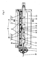
- a device for protecting the chopper drum of a forage harvester which is installed in the front lower roller 1 made of plastic of a feed system, not shown.
- this mounting 4 is only shown on one side in FIG. 1.
- the magnetic field generating device 6 is arranged inside the roller body 5, a base plate 8 with good magnetic conductivity being releasably fastened on the axis 3 via intermediate pieces 7.
- a magnet 9 is attached so that one pole 10 is located within the left half of the roller body 5 and the other pole 11 on the right.
- the pole 10 designed as a north pole, consists of three individual magnetic poles 10 ⁇ ; 10 ⁇ ; 10 ′′′ and the pole 11 also from three individual magnetic poles 11 ⁇ ; 11 ⁇ ; 11 ′′′.
- the individual magnetic poles 10 ⁇ and 11 ⁇ are existing coils consisting of several turns 12; 13 arranged.
- the terminals 15; 17 are connected to one another in an electrically conductive manner, and the connecting terminals 14; 16 lead as a cable 18 to a signal processing device, not shown.
- the location of the individual magnetic poles 10 ⁇ ; 10 ⁇ ; 10 ′′′; 11 ⁇ ; 11 ⁇ ; 11 ′′′ and the take-up spools 12; 13 is fixed on the base plate 8 and, in addition, the entire device is protected against moisture and dirt, all of the above-mentioned components are located in a common plastic housing 19. If a magnetic foreign body approaches the magnetic field generating device 6, the receiving coils 12; 13 induces a voltage causing a current 20; 21 can flow, the size of the distance of the metallic foreign body from the take-up coils 12; 13 is dependent.
- both currents 20; 21, and this one Current goes to the signal evaluation device, which converts the signal obtained in accordance with the selected design, ie visual or acoustic display of the metallic foreign body up to the automatic shutdown of the feed system.
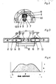
- the detection profile is shown in Fig. 4, from which it can be seen that the detection possibility H is already very close to the side wall 2 and after a steep climb towards the center in the most vulnerable area, ie where most crop arrives, very high and almost constant is.
Landscapes
- Life Sciences & Earth Sciences (AREA)
- Physics & Mathematics (AREA)
- Engineering & Computer Science (AREA)
- Remote Sensing (AREA)
- Environmental Sciences (AREA)
- Electromagnetism (AREA)
- Environmental & Geological Engineering (AREA)
- Geology (AREA)
- General Life Sciences & Earth Sciences (AREA)
- General Physics & Mathematics (AREA)
- Geophysics (AREA)
- Geophysics And Detection Of Objects (AREA)
- Superconductors And Manufacturing Methods Therefor (AREA)
- Preventing Corrosion Or Incrustation Of Metals (AREA)
- Conductive Materials (AREA)
- Cylinder Crankcases Of Internal Combustion Engines (AREA)
- Transition And Organic Metals Composition Catalysts For Addition Polymerization (AREA)
- Processing Of Meat And Fish (AREA)
- Harvesting Machines For Root Crops (AREA)
- Electrical Discharge Machining, Electrochemical Machining, And Combined Machining (AREA)
- Harvester Elements (AREA)
- Combines (AREA)
- Cable Accessories (AREA)
- Laying Of Electric Cables Or Lines Outside (AREA)
- Heat Sensitive Colour Forming Recording (AREA)
Priority Applications (1)
| Application Number | Priority Date | Filing Date | Title |
|---|---|---|---|
| AT86117363T ATE57580T1 (de) | 1985-12-24 | 1986-12-12 | Vorrichtung zum schutz vor metallischen fremdkoerpern. |
Applications Claiming Priority (2)
| Application Number | Priority Date | Filing Date | Title |
|---|---|---|---|
| DD285427 | 1985-12-24 | ||
| DD85285427A DD255432A3 (de) | 1985-12-24 | 1985-12-24 | Vorrichtung zum schutz vor metallischen fremdkoerpern |
Publications (3)
| Publication Number | Publication Date |
|---|---|
| EP0229991A2 true EP0229991A2 (fr) | 1987-07-29 |
| EP0229991A3 EP0229991A3 (en) | 1988-02-24 |
| EP0229991B1 EP0229991B1 (fr) | 1990-10-17 |
Family
ID=5575232
Family Applications (1)
| Application Number | Title | Priority Date | Filing Date |
|---|---|---|---|
| EP86117363A Expired - Lifetime EP0229991B1 (fr) | 1985-12-24 | 1986-12-12 | Dispositif de protection contre des objets métalliques |
Country Status (12)
| Country | Link |
|---|---|
| US (1) | US4758788A (fr) |
| EP (1) | EP0229991B1 (fr) |
| AT (1) | ATE57580T1 (fr) |
| BG (1) | BG51271A1 (fr) |
| CA (1) | CA1269143A (fr) |
| CS (1) | CS267696B1 (fr) |
| DD (1) | DD255432A3 (fr) |
| DE (1) | DE3674999D1 (fr) |
| DK (1) | DK161005C (fr) |
| HU (1) | HU197824B (fr) |
| PL (1) | PL152588B1 (fr) |
| UA (1) | UA5751A1 (fr) |
Cited By (4)
| Publication number | Priority date | Publication date | Assignee | Title |
|---|---|---|---|---|
| EP0324253A2 (fr) * | 1988-01-13 | 1989-07-19 | FORD NEW HOLLAND, INC. (a Delaware corp.) | Détection de métaux à proximité de surfaces ferreuses |
| EP0546509A2 (fr) * | 1991-12-11 | 1993-06-16 | CLAAS SAULGAU GmbH | Dispositif auprès des machines de récolte pour reconnaître des corps étrangers dans la récolte |
| FR2700661A1 (fr) * | 1993-01-22 | 1994-07-29 | Claas Ohg | Dispositif de détection de corps étrangers pour une moissonneuse. |
| EP0988782A1 (fr) * | 1998-09-23 | 2000-03-29 | CLAAS KGaA | Dispositif à localiser des métaux dans un transporteur de produits de récolte |
Families Citing this family (12)
| Publication number | Priority date | Publication date | Assignee | Title |
|---|---|---|---|---|
| US5034690A (en) * | 1988-04-01 | 1991-07-23 | Taliaferro Sam W | Method and apparatus for quantitatively determining whether at least one of two or more ferromagnetic components is missing from an assembly |
| US4866383A (en) * | 1988-04-01 | 1989-09-12 | Taliaferro Sam W | Method and apparatus having load cell responsive to movement of a magnetic field generator for differentiating between materials |
| US5349728A (en) * | 1992-05-27 | 1994-09-27 | Nippon Felt Co., Ltd. | Magnetic position marker and control system for production of felt |
| US5504428A (en) * | 1994-09-16 | 1996-04-02 | Deere & Company | Magnetic metal detector mounted in a feed roll of a harvisting machine |
| US5521514A (en) * | 1995-01-03 | 1996-05-28 | Loral Corporation | Broken tine detector for agricultural machines |
| US5797250A (en) * | 1996-09-27 | 1998-08-25 | Deere & Company | Forage harvester feed roll assembly designed for minimizing false tripping of a metal detector system |
| DE19742060B4 (de) * | 1997-09-24 | 2005-02-03 | Claas Selbstfahrende Erntemaschinen Gmbh | Fremdkörperrückführvorrichtung an Erntemaschinen o. dgl. |
| DE19854562A1 (de) * | 1998-11-26 | 2000-05-31 | Claas Saulgau Gmbh | Einrichtung zur Überwachung der Einzugsbaugruppe einer landwirtschaftlichen Erntemaschine |
| GB2438578A (en) * | 2006-05-30 | 2007-12-05 | Cnh Belgium Nv | Metal object detection system for harvester |
| US7748206B1 (en) | 2009-03-10 | 2010-07-06 | Cnh America Llc | Fruit harvester with system and method for detecting and reducing forces exerted against rigid standing objects |
| GB201121758D0 (en) * | 2011-12-19 | 2012-02-01 | Agco Int Gmbh | Crop processing roller |
| CN113099823B (zh) * | 2021-04-13 | 2022-12-23 | 河森堡(深圳)科技有限公司 | 一种用于庭院绿植修剪机器人的安全高效除草装置 |
Citations (3)
| Publication number | Priority date | Publication date | Assignee | Title |
|---|---|---|---|---|
| US3889249A (en) * | 1971-10-29 | 1975-06-10 | Sperry Rand Corp | Static magnetic field metal detector |
| US3896608A (en) * | 1973-06-25 | 1975-07-29 | Sperry Rand Corp | Static magnetic field metal detector |
| US4344074A (en) * | 1981-04-02 | 1982-08-10 | Sperry Corporation | Magnetic field producing apparatus |
Family Cites Families (4)
| Publication number | Priority date | Publication date | Assignee | Title |
|---|---|---|---|---|
| US3964042A (en) * | 1973-06-25 | 1976-06-15 | Sperry Rand Corporation | Static magnetic field metal detector |
| US3972156A (en) * | 1975-02-24 | 1976-08-03 | Sperry Rand Corporation | Speed-independent static magnetic field metal detector |
| US4290255A (en) * | 1980-10-01 | 1981-09-22 | Sperry Corporation | Feed roll apparatus |
| US4433528A (en) * | 1982-08-30 | 1984-02-28 | Sperry Corporation | Metal detector apparatus |
-
1985
- 1985-12-24 DD DD85285427A patent/DD255432A3/de not_active IP Right Cessation
-
1986
- 1986-11-17 UA UA7774336A patent/UA5751A1/uk unknown
- 1986-11-19 CS CS868384A patent/CS267696B1/cs unknown
- 1986-12-01 BG BG77308A patent/BG51271A1/xx unknown
- 1986-12-05 HU HU865044A patent/HU197824B/hu not_active IP Right Cessation
- 1986-12-12 EP EP86117363A patent/EP0229991B1/fr not_active Expired - Lifetime
- 1986-12-12 AT AT86117363T patent/ATE57580T1/de active
- 1986-12-12 DE DE8686117363T patent/DE3674999D1/de not_active Expired - Fee Related
- 1986-12-15 DK DK602286A patent/DK161005C/da not_active IP Right Cessation
- 1986-12-15 CA CA000525378A patent/CA1269143A/fr not_active Expired - Fee Related
- 1986-12-22 PL PL1986263161A patent/PL152588B1/pl unknown
- 1986-12-23 US US06/946,427 patent/US4758788A/en not_active Expired - Fee Related
Patent Citations (3)
| Publication number | Priority date | Publication date | Assignee | Title |
|---|---|---|---|---|
| US3889249A (en) * | 1971-10-29 | 1975-06-10 | Sperry Rand Corp | Static magnetic field metal detector |
| US3896608A (en) * | 1973-06-25 | 1975-07-29 | Sperry Rand Corp | Static magnetic field metal detector |
| US4344074A (en) * | 1981-04-02 | 1982-08-10 | Sperry Corporation | Magnetic field producing apparatus |
Cited By (8)
| Publication number | Priority date | Publication date | Assignee | Title |
|---|---|---|---|---|
| EP0324253A2 (fr) * | 1988-01-13 | 1989-07-19 | FORD NEW HOLLAND, INC. (a Delaware corp.) | Détection de métaux à proximité de surfaces ferreuses |
| EP0324253A3 (en) * | 1988-01-13 | 1990-02-07 | Ford New Holland, Inc. (A Delaware Corp.) | Metal detection in the vicinity of ferrous boundaries |
| EP0546509A2 (fr) * | 1991-12-11 | 1993-06-16 | CLAAS SAULGAU GmbH | Dispositif auprès des machines de récolte pour reconnaître des corps étrangers dans la récolte |
| EP0546509A3 (fr) * | 1991-12-11 | 1994-04-20 | Claas Saulgau Gmbh | |
| US5343676A (en) * | 1991-12-11 | 1994-09-06 | Claas Saulgau Gmbh | Device for recognizing ferromagnetic foreign bodies, in particular in respect of harvesting machines |
| FR2700661A1 (fr) * | 1993-01-22 | 1994-07-29 | Claas Ohg | Dispositif de détection de corps étrangers pour une moissonneuse. |
| BE1009286A5 (fr) * | 1993-01-22 | 1997-01-07 | Claas Ohg | Dispositif de detection de corps etrangers pour une moissonneuse. |
| EP0988782A1 (fr) * | 1998-09-23 | 2000-03-29 | CLAAS KGaA | Dispositif à localiser des métaux dans un transporteur de produits de récolte |
Also Published As
| Publication number | Publication date |
|---|---|
| ATE57580T1 (de) | 1990-11-15 |
| PL263161A1 (en) | 1987-11-02 |
| BG51271A1 (en) | 1993-04-15 |
| EP0229991A3 (en) | 1988-02-24 |
| DD255432A3 (de) | 1988-04-06 |
| EP0229991B1 (fr) | 1990-10-17 |
| CS838486A1 (en) | 1989-04-14 |
| PL152588B1 (en) | 1991-01-31 |
| HUT43462A (en) | 1987-11-30 |
| UA5751A1 (uk) | 1994-12-29 |
| HU197824B (en) | 1989-06-28 |
| DK602286D0 (da) | 1986-12-15 |
| DK602286A (da) | 1987-06-25 |
| DK161005B (da) | 1991-05-21 |
| US4758788A (en) | 1988-07-19 |
| DE3674999D1 (de) | 1990-11-22 |
| DK161005C (da) | 1991-10-28 |
| CA1269143A (fr) | 1990-05-15 |
| CS267696B1 (en) | 1990-02-12 |
Similar Documents
| Publication | Publication Date | Title |
|---|---|---|
| EP0229991B1 (fr) | Dispositif de protection contre des objets métalliques | |
| EP0702248B1 (fr) | Détecteur de métal pour la reconnaissance de corps étrangers métalliques | |
| EP1366371B1 (fr) | Transformateur destine a un capteur de courant | |
| DE2430147C2 (de) | Erntemaschine | |
| DE102010028017B4 (de) | Bewegtfahrzeugsystem und Verfahren zum Erfassen einer Position eines sich bewegenden Fahrzeugs | |
| DE19606445A1 (de) | Induktive Messvorrichtung zur Messung von einem hohen Gleichstrom überlagerten Wechelstromkomponenten | |
| DE2940201A1 (de) | Feldhaecksler mit metalldetektor | |
| DE2700972B2 (de) | Verfahren und Vorrichtung zur Überwachung von Fremdkörpern in einem Textilfaservlies | |
| DD257178A3 (de) | Anordnung zur erzeugung von steuersignalen | |
| EP0546509B1 (fr) | Dispositif auprès des machines de récolte pour reconnaître des corps étrangers dans la récolte | |
| DE60029573T2 (de) | Verbesserte stromfühleranordnung für niederspannungs-leistungsschalter | |
| DE102009042940A1 (de) | Positionsmesseinrichtung mit sich mehrfach kreuzender Senderwindungsanordnung | |
| DE60026952T2 (de) | Stromsensor | |
| DE19620526A1 (de) | Metalldetektor zum Erkennen von Metall im Erntegutfluß | |
| EP2100102B1 (fr) | Dispositif de mesure | |
| DE2006996A1 (de) | Aufnehmer fur geradlinige Bewegungen oder Winkelbewegungen | |
| DE3511355C2 (fr) | ||
| DE2935887A1 (de) | Vorrichtung zur magnetischen pruefung von stahlblechen oder stahlbaendern | |
| EP2430401A2 (fr) | Ensemble de détection de position pour système de transfert circulaire | |
| DE3019166A1 (de) | Feldhaecksler mit metalldetektor | |
| DE10051553C2 (de) | Einstellvorrichtung für den Schneidspalt an Häckslern | |
| DE4030882C1 (en) | Electrical and magnetic fields insensitive continuous plating plant - has forked sensor head to position strip edge, arms to mount AC transmitter and parallelly connected receiver coils | |
| EP3708978B1 (fr) | Système compacte de mesure directe | |
| DE3205314C2 (de) | Einrichtung zur Eigenortung eines spurgeführten Objektes | |
| EP0974812B1 (fr) | Dispositif pour détecter des étiquettes sur un support |
Legal Events
| Date | Code | Title | Description |
|---|---|---|---|
| PUAI | Public reference made under article 153(3) epc to a published international application that has entered the european phase |
Free format text: ORIGINAL CODE: 0009012 |
|
| AK | Designated contracting states |
Kind code of ref document: A2 Designated state(s): AT BE CH DE FR GB IT LI NL SE |
|
| PUAL | Search report despatched |
Free format text: ORIGINAL CODE: 0009013 |
|
| AK | Designated contracting states |
Kind code of ref document: A3 Designated state(s): AT BE CH DE FR GB IT LI NL SE |
|
| 17P | Request for examination filed |
Effective date: 19880729 |
|
| 17Q | First examination report despatched |
Effective date: 19900201 |
|
| GRAA | (expected) grant |
Free format text: ORIGINAL CODE: 0009210 |
|
| AK | Designated contracting states |
Kind code of ref document: B1 Designated state(s): AT BE CH DE FR GB IT LI NL SE |
|
| REF | Corresponds to: |
Ref document number: 57580 Country of ref document: AT Date of ref document: 19901115 Kind code of ref document: T |
|
| REF | Corresponds to: |
Ref document number: 3674999 Country of ref document: DE Date of ref document: 19901122 |
|
| ET | Fr: translation filed | ||
| ITF | It: translation for a ep patent filed |
Owner name: STUDIO MASSARI S.R.L. |
|
| GBT | Gb: translation of ep patent filed (gb section 77(6)(a)/1977) | ||
| REG | Reference to a national code |
Ref country code: CH Ref legal event code: PUE Owner name: FORTSCHRITT ERNTEMASCHINEN GMBH |
|
| PLBE | No opposition filed within time limit |
Free format text: ORIGINAL CODE: 0009261 |
|
| STAA | Information on the status of an ep patent application or granted ep patent |
Free format text: STATUS: NO OPPOSITION FILED WITHIN TIME LIMIT |
|
| 26N | No opposition filed | ||
| PGFP | Annual fee paid to national office [announced via postgrant information from national office to epo] |
Ref country code: AT Payment date: 19911112 Year of fee payment: 6 |
|
| PGFP | Annual fee paid to national office [announced via postgrant information from national office to epo] |
Ref country code: CH Payment date: 19911121 Year of fee payment: 6 |
|
| ITTA | It: last paid annual fee | ||
| PGFP | Annual fee paid to national office [announced via postgrant information from national office to epo] |
Ref country code: NL Payment date: 19911231 Year of fee payment: 6 |
|
| REG | Reference to a national code |
Ref country code: FR Ref legal event code: TP Ref country code: FR Ref legal event code: CD |
|
| NLS | Nl: assignments of ep-patents |
Owner name: FORTSCHRITT LANDMASCHINEN GMBH TE NEUSTADT, BONDSR |
|
| NLS | Nl: assignments of ep-patents |
Owner name: FORTSCHRITT ERNTEMASCHINEN GMBH TE NEUSTADT, BONDS |
|
| REG | Reference to a national code |
Ref country code: GB Ref legal event code: 732 |
|
| REG | Reference to a national code |
Ref country code: GB Ref legal event code: 732 |
|
| PG25 | Lapsed in a contracting state [announced via postgrant information from national office to epo] |
Ref country code: AT Effective date: 19921212 |
|
| PG25 | Lapsed in a contracting state [announced via postgrant information from national office to epo] |
Ref country code: LI Effective date: 19921231 Ref country code: CH Effective date: 19921231 |
|
| PG25 | Lapsed in a contracting state [announced via postgrant information from national office to epo] |
Ref country code: NL Effective date: 19930701 |
|
| NLV4 | Nl: lapsed or anulled due to non-payment of the annual fee | ||
| REG | Reference to a national code |
Ref country code: CH Ref legal event code: PL |
|
| PGFP | Annual fee paid to national office [announced via postgrant information from national office to epo] |
Ref country code: SE Payment date: 19931116 Year of fee payment: 8 |
|
| PGFP | Annual fee paid to national office [announced via postgrant information from national office to epo] |
Ref country code: BE Payment date: 19931129 Year of fee payment: 8 |
|
| PGFP | Annual fee paid to national office [announced via postgrant information from national office to epo] |
Ref country code: GB Payment date: 19941202 Year of fee payment: 9 |
|
| PG25 | Lapsed in a contracting state [announced via postgrant information from national office to epo] |
Ref country code: SE Effective date: 19941213 |
|
| PG25 | Lapsed in a contracting state [announced via postgrant information from national office to epo] |
Ref country code: BE Effective date: 19941231 |
|
| EAL | Se: european patent in force in sweden |
Ref document number: 86117363.1 |
|
| BERE | Be: lapsed |
Owner name: FORTSCHRITT LANDMASCHINEN G.M.B.H. Effective date: 19941231 |
|
| EUG | Se: european patent has lapsed |
Ref document number: 86117363.1 |
|
| PG25 | Lapsed in a contracting state [announced via postgrant information from national office to epo] |
Ref country code: GB Effective date: 19951212 |
|
| PGFP | Annual fee paid to national office [announced via postgrant information from national office to epo] |
Ref country code: FR Payment date: 19951229 Year of fee payment: 10 |
|
| GBPC | Gb: european patent ceased through non-payment of renewal fee |
Effective date: 19951212 |
|
| PG25 | Lapsed in a contracting state [announced via postgrant information from national office to epo] |
Ref country code: FR Effective date: 19970829 |
|
| REG | Reference to a national code |
Ref country code: FR Ref legal event code: ST |
|
| PGFP | Annual fee paid to national office [announced via postgrant information from national office to epo] |
Ref country code: DE Payment date: 20041130 Year of fee payment: 19 |
|
| PG25 | Lapsed in a contracting state [announced via postgrant information from national office to epo] |
Ref country code: IT Free format text: LAPSE BECAUSE OF NON-PAYMENT OF DUE FEES;WARNING: LAPSES OF ITALIAN PATENTS WITH EFFECTIVE DATE BEFORE 2007 MAY HAVE OCCURRED AT ANY TIME BEFORE 2007. THE CORRECT EFFECTIVE DATE MAY BE DIFFERENT FROM THE ONE RECORDED. Effective date: 20051212 |
|
| PG25 | Lapsed in a contracting state [announced via postgrant information from national office to epo] |
Ref country code: DE Free format text: LAPSE BECAUSE OF NON-PAYMENT OF DUE FEES Effective date: 20060701 |