EP0227486A2 - Sprühtrocknungsverfahren und -vorrichtung - Google Patents
Sprühtrocknungsverfahren und -vorrichtung Download PDFInfo
- Publication number
- EP0227486A2 EP0227486A2 EP86310183A EP86310183A EP0227486A2 EP 0227486 A2 EP0227486 A2 EP 0227486A2 EP 86310183 A EP86310183 A EP 86310183A EP 86310183 A EP86310183 A EP 86310183A EP 0227486 A2 EP0227486 A2 EP 0227486A2
- Authority
- EP
- European Patent Office
- Prior art keywords
- spray drying
- porous membrane
- powder
- feed liquid
- drying chamber
- Prior art date
- Legal status (The legal status is an assumption and is not a legal conclusion. Google has not performed a legal analysis and makes no representation as to the accuracy of the status listed.)
- Granted
Links
Images


Classifications
-
- B—PERFORMING OPERATIONS; TRANSPORTING
- B01—PHYSICAL OR CHEMICAL PROCESSES OR APPARATUS IN GENERAL
- B01D—SEPARATION
- B01D1/00—Evaporating
- B01D1/16—Evaporating by spraying
- B01D1/18—Evaporating by spraying to obtain dry solids
-
- Y—GENERAL TAGGING OF NEW TECHNOLOGICAL DEVELOPMENTS; GENERAL TAGGING OF CROSS-SECTIONAL TECHNOLOGIES SPANNING OVER SEVERAL SECTIONS OF THE IPC; TECHNICAL SUBJECTS COVERED BY FORMER USPC CROSS-REFERENCE ART COLLECTIONS [XRACs] AND DIGESTS
- Y10—TECHNICAL SUBJECTS COVERED BY FORMER USPC
- Y10S—TECHNICAL SUBJECTS COVERED BY FORMER USPC CROSS-REFERENCE ART COLLECTIONS [XRACs] AND DIGESTS
- Y10S159/00—Concentrating evaporators
- Y10S159/02—Entrainment
-
- Y—GENERAL TAGGING OF NEW TECHNOLOGICAL DEVELOPMENTS; GENERAL TAGGING OF CROSS-SECTIONAL TECHNOLOGIES SPANNING OVER SEVERAL SECTIONS OF THE IPC; TECHNICAL SUBJECTS COVERED BY FORMER USPC CROSS-REFERENCE ART COLLECTIONS [XRACs] AND DIGESTS
- Y10—TECHNICAL SUBJECTS COVERED BY FORMER USPC
- Y10S—TECHNICAL SUBJECTS COVERED BY FORMER USPC CROSS-REFERENCE ART COLLECTIONS [XRACs] AND DIGESTS
- Y10S159/00—Concentrating evaporators
- Y10S159/28—Porous member
Definitions
- the present invention relates to a spray drying process and an apparatus therefor. More particularly, the present invention relates to a spray drying process and an apparatus therefor, both using a spray drying chamber formed by a porous membrane.
- Spray drying processes and apparatuses therefor basically have three essential functions, namely, (1) spraying of a feed liquid to form microdrops, (2) drying of the microdrops to produce a powder and (3) separation and recovery of the powder product.
- These spray drying apparatuses are ordinarily equipped with an atomizer, a drying chamber and a fine powder collector to perform each of said functions.
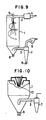
- a feed liquid is sprayed from a nozzle 5 and momentarily heated by hot gas (heated air) blown from a hot gas inlet 2, whereby the liquid component of the feed liquid is evaporated and the solid component is converted to a fine (dried) powder.
- the majority of the fine powder is taken out as a product through a rotary valve 6, but part of the fine powder is carried by an exhaust gas into a cyclone collector (hereinafter referred to as "a cyclone") through a discharge gas outlet 3 and recovered from a rotary valve 8.
- a cyclone collector hereinafter referred to as "a cyclone
- the spray drying apparatus of Fig. 10 is same as that of Fig. 9 except that as the atomizer, a rotary spraying disc 10 is used in place of the nozzle 5.
- a fine powder as a product is recovered in two portions from the apparatus main body (drying chamber) and the cyclone, respectively.
- the portion of the product having a heavier weight and larger particle diameters are taken out from the apparatus main body (drying chamber) and the portion of the product having a lighter weight and smaller particle diameters from the cyclone.
- the more grade smaller quantity production system requires more frequent product change, which in turn requires rapid and complete cleaning of a solid which has adhered to the inner wall of a drying chamber.
- Such cleaning is necessary because (1) efficient operation of the more grade smaller quantity production system requires a cleaning time as short as possible and (2) production of higher purity and higher quality products requires complete cleaning of an adhered solid at each product change. In actuality, complete cleaning is extremely difficult. Moreover, when the product is harmful to human bodies, direct contact with the product must be avoided making the cleaning very difficult.
- an object of the present invention is to provide a spray drying process suited for more grade smaller quantity production, as well as an apparatus therefor.
- Another object of the present invention is to provide a spray drying process capable of producing a fine powder of high purity, as well as an apparatus therefor.
- Still another object of the present invention is to provide a spray drying process capable of effecting spray drying with smaller total facility, as well as an apparatus therefor.
- the spray drying process of the present invention uses a spray drying chamber formed by a heat-resistant porous membrane and this porous membrane enables high-efficiency separation of a discharge gas and a produced powder; whereby a total amount of the powder product can be obtained directly from the spray drying chamber.
- the spray drying apparatus of the present invention uses a spray drying chamber formed by a heat-resistant porous membrane and equipped with an inlet for heated air, an outlet for discharge gas, an outlet for powder product and a means for atomization of feed liquid.
- the present invention further provides a spray drying apparatus of integration type wherein at least one spray drying chamber formed by a heat-resistant porous membrane is accommodated in a housing.
- This apparatus comprises a housing having upper and lower rooms. In the upper room, there are arranged at least one unit for generation of hot gas, at least one unit for distribution of hot gas, at least one unit for atomization of feed liquid and at least one unit for exhaust gas. In the lower room, at least one unit for recovery of produced powder is arranged movably. Between each feed liquid atomization unit in the upper room and each corresponding produced product recovery unit in the lower room, there is detachably arranged one spray drying chamber formed by a heat-resistant porous membrane.
- the porous membrane used in the present invention is preferred to have a bag-like or cylindrical shape.
- the membrane must be heat-resistant and it is preferable to be excellent in powder releasability.
- the porous membrane must withstand such a high temperature. Further, since a fine powder constantly adheres to and deposits on the porous membrane, the membrane is preferred to be excellent in powder releasability in order to allow its continuous use. Furthermore, the porous membrane has a function of separating a fine powder produced and an exhaust gas.
- the porous membrane having such requirements has no particular restriction with respect to the type.
- fiber-made cloths or laminates each consisting of two different such cloths.
- laminates of (1) a powder-releasable, reticulate membrane and (2) a woven or unwoven cloth as a reinforcing material are used.
- the reticulate membrane are a membrane of polytetrafluoroethylene (PTFE) (brand name: Teflon) type and a polytrifluoroethylene type membrane
- PTFE polytetrafluoroethylene
- the woven or unwoven cloth are cloths made from a polyimide, a heat-resistant nylon, a polyester or an aramid.
- the whole portion of the spray drying chamber is formed by a single porous membrane. This makes detaching of the chamber easy and accordingly its maintenance very simple.
- a feed liquid is sprayed to form microdrops and the microdrops are momentarily dried by hot gas blown from its inlet and having an inlet temperature of 120° to 280°C to be converted into a fine powder and a gas.
- a part of the fine powder deposits on the bottom of the spray drying chamber owing to the own weight, while the gas is separated from the rest of the fine powder by being pressed through the pores of the porous membrane and is discharged outside through an outlet for exhaust gas.
- the total portion of the fine powder is separated from the gas and, as a result, there occurs no nonuniformity in the composition of the fine powder product.
- the porous membrane in general has excellent powder releasability, the adhered powder can be easily removed from the porous membrane in a short time by mechanical vibration, air injection from the opposite side (pulse air or reverse jet) or the like.
- complete removal (cleaning) of the powder from the membrane without causing contamination with impurities it can be done by replacing the porous membrane with a new one from outside without touching the product inside the membrane. This replacement is easy when the porous membrane has a bag-like shape.
- Separation of a fine powder and a gas by the porous membrane is ordinarily conducted by passing a gas containing a fine powder through the meshes of the fiber constituting the porous membrane and allowing the fine powder to remain on the meshes.
- this filtration is not simple.
- the meshes are usually many times as large as the particle sizes of the fine powder; accordingly, the fine powder is collected not only on the surface of the filtration cloth but also partially inside the cloth.
- such a filter cloth is used primarily for a fine powder of good solubility.
- the porous membrane used in the present invention is a laminate of (1) a reticulate membrane as mentioned previously, having good powder releasability and capable of conducting surface filtration and (2) a woven or unwoven cloth as mentioned previously, of excellent heat resistance and strength as a carrier for the membrane (1).
- the effect of the present invention can be enhanced by the use of such a laminate.
- the diameters of the particles which can be captured by the porous membrane of the present invention can vary from 0.1 ⁇ m to several millimeters.
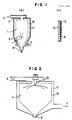
- Fig. 1 shows an embodiment of the spray drying apparatus of the present invention for carrying out the spray drying process of the present invention.
- Fig. 1(a) is a schematic sectional view of the whole portion of the apparatus and
- Fig. 1(b) is a partially enlarged sectional view of the porous membrane forming the spray drying chamber of the apparatus.
- a spray drying chamber 1 formed by a bag-like porous membrane 15 is arranged inside the main body 11 of the spray drying apparatus along the inner wall of the main body 11.
- the porous membrane 15 is constituted by a laminate of a reticulate membrane 13 and a filter cloth 14 as a reinforcing material.
- Hot gas X is sent into the spray drying chamber 1 from the top of the main body 11 through an inlet 2 and is allowed to make counter-flow contact with a feed liquid sprayed upward from the lower portion of the spray drying chamber 1 through a nozzle 5.
- a fine powder produced enters a product receiver (not shown) from an outlet 6 of seal valve type.
- a gas after drying is separated from a fine powder A via the porous membrane 15 forming the outer wall of the spray drying chamber 1 and is then discharged outside from a discharge gas outlet 3 installed at the lower portion of the main body 11.
- Fig. 2 is a schematic sectional view showing other embodiment of the spray drying apparatus of the present invention.
- Fig. 2 is different from Fig. 1 in that a rotary spraying disc 10 is used as an atomizer, in place of the nozzle 5 and both hot gas X and a feed liquid from the rotary spraying disc 10 are introduced downward as parallel flows.
- the structure of the apparatus of Fig. 2 is approximately same as that of Fig. 1.
- Fig. 3 to Fig. 5 are schematic sectional views also showing other embodiments of the spray drying apparatus of the present invention.
- hot gas X and a feed liquid from a nozzle 5 are introduced downward as parallel flows.
- hot gas X and a feed liquid from a nozzle 5 are introduced upward as parallel flows.
- hot gas X and a feed liquid from a nozzle 5 are introduced from the side of the spray drying chamber 1.
- a blow-off mechanism Z for blowing off a fine powder produced.
- pulse air is sent into a main body 11 from the opposite direction through a line 12, whereby a fine powder A which has adhered to a porous membrane 15 is blown off.
- Fig. 6 and Fig. 7 each shows an embodiment of the spray drying apparatus of integration type according to the present invention wherein each unit of the apparatus is accommodated in a housing.
- Fig. 6 is a perspective view of the whole portion of the apparatus.
- Fig. 7(a) is a plan view of the upper room of the housing of the apparatus.
- Fig. 7(b) is a plan view of the lower room of the housing of the apparatus.
- a housing 16 consists of an upper room 17 and a lower room 18.
- the same sets (i.e. three sets) of units 23 for recovery of fine powder product there are arranged, below the feed liquid atomization units 21, the same sets (i.e. three sets) of units 23 for recovery of fine powder product.
- the lower room 18 there are further arranged units 24a and 24b for blowing-off of fine powder and a unit 25 for preparation of feed liquid.
- the same sets (i.e. three sets) of spray drying chambers 1 A large number of bag-like porous members each to be used as a spray drying chamber 1 are stored in the lower room.
- FIG. 8 there is explained the operation of the spray drying apparatus of integration type according to the present invention.
- the apparatus of Fig. 8 accommodates two sets of spray drying chambers for producing different products G and H. Explanation is made on one set.
- a feed liquid G F supplied from a feed liquid preparation unit 25 through a pipe 27 is sprayed into a drying chamber 1 by a feed liquid atomization unit 21 to form microdrops, and the microdrops are momentarily dried by hot gas X blown from a hot gas generation unit 19 through a hot gas distribution unit, to be converted into a fine powder and a vapor.
- the fine powder is recovered as a product G1 by a fine powder receiver 23.
- the porous membrane constituting the spray drying chamber 1 is removed and can be rapidly replaced by a porous membrane of exclusive use for G2 or G3 which is stored nearby.
- Another set is also operated in the basically same manner.
- the gas is separated from the fine powder through the pores of the porous membrane 26 and is discharged outside from a common discharge unit 22.
- a feed liquid containing 60 % of stabilized zirconia (Ca 0.15 Zr 0.85 O 1.85 ) or 70 % of lanthanum-added barium titanate [BaTiO3 + 0.01(La2O3)] was sprayed at a rate of 150 kg/hr.
- the drying chamber of the apparatus had dimensions of 2,500 mm in diameter, 2,500 mm in straight body height and 4,300 mm in total height, and had a cylindrical shape at the upper portion and a cone shape at the lower portion.
- the porous membrane forming the drying chamber was a laminate of a heat-resistant unwoven nylon cloth and a polytetrafluoroethylene.
- the inlet temperature of heated air was 220°C and the exhaust gas temperature was 120°C.
- the spray drying operation of each feed liquid was conducted.
- the fine powder products obtained had the following properties.
- (1) refers to stabilized zirconia and (2) refers to lanthanum-added barium titanate.
- the time required for product change was as short as about 40 minutes.
- a feed liquid containing 70 % of lanthanum-added barium titanate [BaTiO3 + 0.01, 0.015 or 0.02 (La2O3)] was sprayed at a rate of 100 kg/hr.
- the drying apparatus was of G type.
- the drying chamber of the apparatus had dimensions of 2,000 mm in diameter, 500 mm in straight body height and 3,500 mm in total height, and had a cylindrical shape in the upper portion and a cone shape in the lower portion.
- the porous membrane forming the drying chamber was a laminate of a heat-resistant unwoven nylon cloth and a polytetrafluoroethylene. Each one membrane was used for each feed liquid.
- the inlet temperature of heated air was about 220°C and the exhaust gas temperature was 120°C.
- the spray drying operation of each feed liquid was conducted.
- the fine powder products had the following properties.
- (1) refers to the case of 0.01% lanthanum addition
- (2) refers to the case of 0.015% lanthanum addition
- (3) refers to the case of 0.02% lanthanum addition.
- the time required for product change was as short as about 30 minutes.
- the spray drying apparatus of the present invention uses a spray drying chamber formed by a porous membrane; as a result, there takes place no discharge, out of the apparatus, of the portion of a powder product having smaller particle diameters together with an exhaust gas, as experienced with the conventional spray drying apparatuses.
- a spray drying chamber formed by a porous membrane; as a result, there takes place no discharge, out of the apparatus, of the portion of a powder product having smaller particle diameters together with an exhaust gas, as experienced with the conventional spray drying apparatuses.
- there is no nonuniformity in product composition cleaning and blowing-off of adhered fine powder can be conducted rapidly and easily even in frequent product change inevitable with a more grade smaller quantity production system; as a result, a fine powder of higher quality and higher purity can be produced.
- each several sets (each set has about the same size) of other necessary units such as hot gas generation units, hot gas distribution units and feed liquid atomization units and there are further stored in the housing a large number of porous membranes for each different product.
- Such a spray drying apparatus can provide the same performance as several tens of conventional spray drying apparatuses, with a far smaller land area and a far lower facility cost.
- the spray drying process and apparatus of the present invention can produce a fine powder of high purity, is suited for use in a more grade smaller quantity production system, and accordingly can be preferably utilized in the production of high purity products such as medicines and fine ceramics.
Landscapes
- Chemical & Material Sciences (AREA)
- Chemical Kinetics & Catalysis (AREA)
- Vaporization, Distillation, Condensation, Sublimation, And Cold Traps (AREA)
Applications Claiming Priority (4)
| Application Number | Priority Date | Filing Date | Title |
|---|---|---|---|
| JP60292557A JPH0675641B2 (ja) | 1985-12-27 | 1985-12-27 | 噴霧乾燥方法及び装置 |
| JP292557/85 | 1985-12-27 | ||
| JP20000486A JPH072201B2 (ja) | 1986-08-28 | 1986-08-28 | 噴霧乾燥装置 |
| JP200004/86 | 1986-08-28 |
Publications (3)
| Publication Number | Publication Date |
|---|---|
| EP0227486A2 true EP0227486A2 (de) | 1987-07-01 |
| EP0227486A3 EP0227486A3 (en) | 1988-03-16 |
| EP0227486B1 EP0227486B1 (de) | 1991-11-27 |
Family
ID=26511897
Family Applications (1)
| Application Number | Title | Priority Date | Filing Date |
|---|---|---|---|
| EP86310183A Expired - Lifetime EP0227486B1 (de) | 1985-12-27 | 1986-12-29 | Sprühtrocknungsverfahren und -vorrichtung |
Country Status (5)
| Country | Link |
|---|---|
| US (2) | US4809442A (de) |
| EP (1) | EP0227486B1 (de) |
| KR (1) | KR900006050B1 (de) |
| CN (1) | CN1007319B (de) |
| DE (1) | DE3682662D1 (de) |
Cited By (10)
| Publication number | Priority date | Publication date | Assignee | Title |
|---|---|---|---|---|
| EP0298864A1 (de) * | 1987-07-08 | 1989-01-11 | Laboratoire L. Lafon | Filter, das ein durch Gefriertrocknung hergestelltes Material enthält, Herstellung und Verwendung desselben, insbesondere in der Galenik |
| JPS648902U (de) * | 1987-07-06 | 1989-01-18 | ||
| JPS648908U (de) * | 1987-07-06 | 1989-01-18 | ||
| JPS648907U (de) * | 1987-07-06 | 1989-01-18 | ||
| JPS648904U (de) * | 1987-07-06 | 1989-01-18 | ||
| WO1997021477A1 (de) * | 1995-12-09 | 1997-06-19 | Henkel Kommanditgesellschaft Auf Aktien | Zerstäubungstrockner und verfahren zum betreiben eines solchen trockners |
| DE3890558C2 (de) * | 1987-07-06 | 1997-08-21 | Tdk Corp | Sprühtrockner |
| EP1905507A1 (de) * | 2006-09-26 | 2008-04-02 | Herbert Dr. h.c. Hüttlin | Kombiniertes Produktbehälter-/Filtersystem |
| GB2531009A (en) * | 2014-10-07 | 2016-04-13 | Vectura Ltd | Spray Drier Apparatus |
| CN116139769A (zh) * | 2022-11-03 | 2023-05-23 | 郑州嵩山硼业科技有限公司 | 一种用于无压烧结陶瓷专用造粒方法 |
Families Citing this family (26)
| Publication number | Priority date | Publication date | Assignee | Title |
|---|---|---|---|---|
| JPS6411632A (en) * | 1987-07-06 | 1989-01-17 | Tdk Corp | Fluidization granulator |
| US5223088A (en) * | 1991-02-15 | 1993-06-29 | Niro A/S | Apparatus for producing concentrated aqueous slurries and spray dried particulate products |
| KR0159947B1 (ko) * | 1991-03-12 | 1998-11-16 | 마사아키 오카와라 | 분수형 가압 2류체 노즐 장치와 그것을 편입하여 이루어지는 스프레이 드라이어 장치, 및 가압 2류체에 있어서의 액적 경 제어법 |
| US5596817A (en) * | 1992-05-21 | 1997-01-28 | Niro Holding A/S | Method and an apparatus for minimizing deposits in a drying chamber |
| US5423132A (en) * | 1992-09-30 | 1995-06-13 | Graber; David A. | Dryer apparatus using hot gases in free standing vortex |
| JP3585654B2 (ja) * | 1996-07-11 | 2004-11-04 | 株式会社パウダリングジャパン | 2段乾燥式スプレードライヤー装置 |
| CN1075518C (zh) * | 1998-09-14 | 2001-11-28 | 中国科学院广州化学研究所 | 一种从苎麻中提取果胶的方法 |
| US6463675B1 (en) * | 1999-09-29 | 2002-10-15 | Niro A/S | Process and a plant for spray drying |
| US6684917B2 (en) * | 2001-12-17 | 2004-02-03 | The University Of Western Ontario | Apparatus for volumetric metering of small quantity of powder from fluidized beds |
| WO2009041900A1 (en) | 2007-09-24 | 2009-04-02 | Dustgun Technologies Ab | System and method for producing dry formulations |
| US8176655B2 (en) * | 2008-12-16 | 2012-05-15 | Spx Flow Technology Danmark A/S | Vapor atmosphere spray dryer |
| US9332776B1 (en) | 2010-09-27 | 2016-05-10 | ZoomEssence, Inc. | Methods and apparatus for low heat spray drying |
| US8939388B1 (en) | 2010-09-27 | 2015-01-27 | ZoomEssence, Inc. | Methods and apparatus for low heat spray drying |
| CN102350066A (zh) * | 2011-07-30 | 2012-02-15 | 淮北市惠尔普建筑陶瓷有限公司 | 一种高效节能环保喷雾干燥塔 |
| WO2015109384A1 (en) | 2014-01-27 | 2015-07-30 | Her Majesty The Queen In Right Of Canada As Represented By The Minister Of Natural Resources | Process for drying and powderizing functional foods, nutraceuticals, and natural health ingredients |
| CN105031956A (zh) * | 2014-11-26 | 2015-11-11 | 安徽嘉智信诺化工有限公司 | 一种喷雾干燥装置 |
| CN105135853A (zh) * | 2015-09-07 | 2015-12-09 | 发基化学品(张家港)有限公司 | 一种硬脂酸盐干燥控制装置 |
| AR106558A1 (es) | 2015-11-03 | 2018-01-24 | Spraying Systems Co | Aparato y método de secado por pulverización |
| US9993787B1 (en) | 2017-08-04 | 2018-06-12 | ZoomEssence, Inc. | Ultrahigh efficiency spray drying apparatus and process |
| US10155234B1 (en) | 2017-08-04 | 2018-12-18 | ZoomEssence, Inc. | Ultrahigh efficiency spray drying apparatus and process |
| US9861945B1 (en) | 2017-08-04 | 2018-01-09 | ZoomEssence, Inc. | Ultrahigh efficiency spray drying apparatus and process |
| US10486173B2 (en) | 2017-08-04 | 2019-11-26 | ZoomEssence, Inc. | Ultrahigh efficiency spray drying apparatus and process |
| AU2018312095B2 (en) | 2017-08-04 | 2021-10-28 | ZoomEssence, Inc. | Ultrahigh efficiency spray drying apparatus and process |
| US11619445B2 (en) | 2017-08-31 | 2023-04-04 | Capsugel Belgium Nv | Single-use spray drying components and methods of using the same |
| US10569244B2 (en) | 2018-04-28 | 2020-02-25 | ZoomEssence, Inc. | Low temperature spray drying of carrier-free compositions |
| ES2912038A1 (es) * | 2022-01-14 | 2022-05-24 | Asociacion De Investig De Las Industrias Ceramicas Aice | Equipo de microatomizacion para la caracterizacion de muestras de materias primas y procedimiento de caracterizacion de una muestra microatomizada |
Family Cites Families (13)
| Publication number | Priority date | Publication date | Assignee | Title |
|---|---|---|---|---|
| US1090740A (en) * | 1911-04-03 | 1914-03-17 | Wharton B Mclaughlin | Method for desiccating fluid substances. |
| US1512776A (en) * | 1921-05-10 | 1924-10-21 | Gerald A Lough | Drying apparatus |
| US1897729A (en) * | 1928-03-22 | 1933-02-14 | Albert P Hunt | Molasses product and method of making the same |
| GB382129A (en) * | 1932-01-08 | 1932-10-20 | Metallgesellschaft Ag | Improvements in or relating to spray-drying apparatus |
| US3011543A (en) * | 1957-07-12 | 1961-12-05 | Jr Samuel L Mccormick | Spray dryer |
| US3633283A (en) * | 1967-07-06 | 1972-01-11 | Nestle Sa Soc Ass Tech Prod | Drying apparatus |
| US3648753A (en) * | 1969-08-13 | 1972-03-14 | Henningsen Foods | Spray dryer air flow control |
| US4012846A (en) * | 1975-07-28 | 1977-03-22 | Silva Rene N | Apparatus for concentrating liquid-solid mixture |
| JPS56121425A (en) * | 1980-02-25 | 1981-09-24 | Hiroshi Wakayama | Packaging container enclosing live bait and method |
| GB2099969A (en) * | 1981-04-25 | 1982-12-15 | Greenbank Darwen Engineering L | A dryer for particulate material |
| JPS5832601A (ja) * | 1981-08-20 | 1983-02-25 | Asahi Denka Kogyo Kk | 潤滑性被覆用組成物 |
| DE3301872A1 (de) * | 1983-01-21 | 1984-07-26 | Henkel KGaA, 4000 Düsseldorf | Zerstaeubungstrockner und verfahren zum betrieb des trockners |
| US4702799A (en) * | 1985-09-03 | 1987-10-27 | Nestec S.A. | Dryer and drying method |
-
1986
- 1986-12-24 CN CN86108835A patent/CN1007319B/zh not_active Expired
- 1986-12-27 KR KR1019860011328A patent/KR900006050B1/ko not_active Expired
- 1986-12-29 US US06/947,245 patent/US4809442A/en not_active Expired - Lifetime
- 1986-12-29 DE DE8686310183T patent/DE3682662D1/de not_active Expired - Lifetime
- 1986-12-29 EP EP86310183A patent/EP0227486B1/de not_active Expired - Lifetime
-
1988
- 1988-04-18 US US07/182,604 patent/US4896436A/en not_active Expired - Lifetime
Cited By (12)
| Publication number | Priority date | Publication date | Assignee | Title |
|---|---|---|---|---|
| JPS648902U (de) * | 1987-07-06 | 1989-01-18 | ||
| JPS648908U (de) * | 1987-07-06 | 1989-01-18 | ||
| JPS648907U (de) * | 1987-07-06 | 1989-01-18 | ||
| JPS648904U (de) * | 1987-07-06 | 1989-01-18 | ||
| DE3890558C2 (de) * | 1987-07-06 | 1997-08-21 | Tdk Corp | Sprühtrockner |
| EP0298864A1 (de) * | 1987-07-08 | 1989-01-11 | Laboratoire L. Lafon | Filter, das ein durch Gefriertrocknung hergestelltes Material enthält, Herstellung und Verwendung desselben, insbesondere in der Galenik |
| WO1997021477A1 (de) * | 1995-12-09 | 1997-06-19 | Henkel Kommanditgesellschaft Auf Aktien | Zerstäubungstrockner und verfahren zum betreiben eines solchen trockners |
| US6237247B1 (en) | 1995-12-09 | 2001-05-29 | Henkel Kommanditgesellschaft Auf Aktien | Apparatus and method for a spray dryer |
| EP1905507A1 (de) * | 2006-09-26 | 2008-04-02 | Herbert Dr. h.c. Hüttlin | Kombiniertes Produktbehälter-/Filtersystem |
| GB2531009A (en) * | 2014-10-07 | 2016-04-13 | Vectura Ltd | Spray Drier Apparatus |
| CN116139769A (zh) * | 2022-11-03 | 2023-05-23 | 郑州嵩山硼业科技有限公司 | 一种用于无压烧结陶瓷专用造粒方法 |
| CN116139769B (zh) * | 2022-11-03 | 2023-12-19 | 郑州嵩山硼业科技有限公司 | 一种用于无压烧结陶瓷专用造粒方法 |
Also Published As
| Publication number | Publication date |
|---|---|
| EP0227486A3 (en) | 1988-03-16 |
| DE3682662D1 (de) | 1992-01-09 |
| EP0227486B1 (de) | 1991-11-27 |
| CN86108835A (zh) | 1987-07-01 |
| CN1007319B (zh) | 1990-03-28 |
| US4809442A (en) | 1989-03-07 |
| KR900006050B1 (ko) | 1990-08-20 |
| US4896436A (en) | 1990-01-30 |
| KR870005667A (ko) | 1987-07-06 |
Similar Documents
| Publication | Publication Date | Title |
|---|---|---|
| US4809442A (en) | Spray drying process and apparatus therefor | |
| KR100908903B1 (ko) | 분무 건조에 의한 조립 방법 및 그 장치 | |
| US9788566B2 (en) | Process for drying and powderizing functional foods, nutraceuticals, and natural health ingredients | |
| US3960323A (en) | Powder spray system | |
| US3870375A (en) | Powder spray system | |
| CN1092993C (zh) | 喷雾干燥装置 | |
| US4973459A (en) | Apparatus and method for removing gaseous contaminants and particulate contaminants from a hot gas stream | |
| WO1988003441A1 (en) | Powder spray system | |
| JPH0693123A (ja) | 多孔質ポリテトラフルオロエチレン構造体及びその製造方法 | |
| US5135611A (en) | Method and apparatus for combined spray drying and gas cleaning | |
| JP3301610B2 (ja) | 噴霧乾燥用多孔質フィルター | |
| EP0944422B1 (de) | Heissgas Filter und Zusammenbau | |
| EP1152067B1 (de) | Kaltes gasdynamisches Spritzverfahren | |
| JPS62152501A (ja) | 噴霧乾燥方法及び装置 | |
| US20050155333A1 (en) | Cleaning device for a bundle of tubular filter elements designed with one end open, preferably of an industrial dust filter | |
| GB2218015A (en) | Fluidized bed granulator | |
| US4726821A (en) | Apparatus for the treatment of substrates in a gas stream | |
| JPS62152502A (ja) | 噴霧乾燥方法及び装置 | |
| CN213611235U (zh) | 一种内壁防粘喷雾干燥造粒塔 | |
| CN1069844C (zh) | 多功能组合式压缩空气净化器 | |
| JPH0517123Y2 (de) | ||
| CN209696840U (zh) | 连续式压力喷雾沸腾制粒干燥系统 | |
| US3521428A (en) | Phase separation | |
| JPS6359301A (ja) | 噴霧乾燥装置 | |
| WO1990007382A1 (en) | Filter for separating particles from gases |
Legal Events
| Date | Code | Title | Description |
|---|---|---|---|
| PUAI | Public reference made under article 153(3) epc to a published international application that has entered the european phase |
Free format text: ORIGINAL CODE: 0009012 |
|
| AK | Designated contracting states |
Kind code of ref document: A2 Designated state(s): DE FR GB |
|
| PUAL | Search report despatched |
Free format text: ORIGINAL CODE: 0009013 |
|
| AK | Designated contracting states |
Kind code of ref document: A3 Designated state(s): DE FR GB |
|
| 17P | Request for examination filed |
Effective date: 19880329 |
|
| 17Q | First examination report despatched |
Effective date: 19890517 |
|
| GRAA | (expected) grant |
Free format text: ORIGINAL CODE: 0009210 |
|
| AK | Designated contracting states |
Kind code of ref document: B1 Designated state(s): DE FR GB |
|
| REF | Corresponds to: |
Ref document number: 3682662 Country of ref document: DE Date of ref document: 19920109 |
|
| ET | Fr: translation filed | ||
| PLBE | No opposition filed within time limit |
Free format text: ORIGINAL CODE: 0009261 |
|
| STAA | Information on the status of an ep patent application or granted ep patent |
Free format text: STATUS: NO OPPOSITION FILED WITHIN TIME LIMIT |
|
| 26N | No opposition filed | ||
| REG | Reference to a national code |
Ref country code: GB Ref legal event code: IF02 |
|
| PGFP | Annual fee paid to national office [announced via postgrant information from national office to epo] |
Ref country code: FR Payment date: 20051208 Year of fee payment: 20 |
|
| PGFP | Annual fee paid to national office [announced via postgrant information from national office to epo] |
Ref country code: DE Payment date: 20051222 Year of fee payment: 20 |
|
| PGFP | Annual fee paid to national office [announced via postgrant information from national office to epo] |
Ref country code: GB Payment date: 20051228 Year of fee payment: 20 |
|
| PG25 | Lapsed in a contracting state [announced via postgrant information from national office to epo] |
Ref country code: GB Free format text: LAPSE BECAUSE OF EXPIRATION OF PROTECTION Effective date: 20061228 |
|
| REG | Reference to a national code |
Ref country code: GB Ref legal event code: PE20 |