EP0227422A2 - Procédé de récupération de tabac - Google Patents
Procédé de récupération de tabac Download PDFInfo
- Publication number
- EP0227422A2 EP0227422A2 EP86309837A EP86309837A EP0227422A2 EP 0227422 A2 EP0227422 A2 EP 0227422A2 EP 86309837 A EP86309837 A EP 86309837A EP 86309837 A EP86309837 A EP 86309837A EP 0227422 A2 EP0227422 A2 EP 0227422A2
- Authority
- EP
- European Patent Office
- Prior art keywords
- roller
- tobacco
- tobacco material
- groove
- grooves
- Prior art date
- Legal status (The legal status is an assumption and is not a legal conclusion. Google has not performed a legal analysis and makes no representation as to the accuracy of the status listed.)
- Withdrawn
Links
- 241000208125 Nicotiana Species 0.000 title claims abstract description 188
- 235000002637 Nicotiana tabacum Nutrition 0.000 title claims abstract description 188
- 238000000034 method Methods 0.000 title claims abstract description 50
- 239000000463 material Substances 0.000 claims abstract description 148
- 239000000428 dust Substances 0.000 claims abstract description 7
- 230000006835 compression Effects 0.000 claims description 30
- 238000007906 compression Methods 0.000 claims description 30
- 230000001747 exhibiting effect Effects 0.000 claims description 6
- 239000011230 binding agent Substances 0.000 claims description 5
- 239000002699 waste material Substances 0.000 abstract description 6
- 239000000203 mixture Substances 0.000 description 11
- 239000002245 particle Substances 0.000 description 9
- 239000000945 filler Substances 0.000 description 7
- 238000004519 manufacturing process Methods 0.000 description 7
- XLYOFNOQVPJJNP-UHFFFAOYSA-N water Substances O XLYOFNOQVPJJNP-UHFFFAOYSA-N 0.000 description 7
- 235000019504 cigarettes Nutrition 0.000 description 6
- 230000027455 binding Effects 0.000 description 5
- 239000000835 fiber Substances 0.000 description 4
- 235000019505 tobacco product Nutrition 0.000 description 4
- 229910000975 Carbon steel Inorganic materials 0.000 description 3
- 239000010962 carbon steel Substances 0.000 description 3
- 238000001035 drying Methods 0.000 description 3
- 238000000227 grinding Methods 0.000 description 3
- 238000010008 shearing Methods 0.000 description 3
- 238000013459 approach Methods 0.000 description 2
- 230000015556 catabolic process Effects 0.000 description 2
- 238000010276 construction Methods 0.000 description 2
- 238000012986 modification Methods 0.000 description 2
- 230000004048 modification Effects 0.000 description 2
- 238000000926 separation method Methods 0.000 description 2
- 210000003462 vein Anatomy 0.000 description 2
- 229910000851 Alloy steel Inorganic materials 0.000 description 1
- 239000000654 additive Substances 0.000 description 1
- 238000005054 agglomeration Methods 0.000 description 1
- 230000002776 aggregation Effects 0.000 description 1
- 230000001419 dependent effect Effects 0.000 description 1
- 239000002657 fibrous material Substances 0.000 description 1
- 239000012634 fragment Substances 0.000 description 1
- 238000003754 machining Methods 0.000 description 1
- 239000011159 matrix material Substances 0.000 description 1
- 239000007769 metal material Substances 0.000 description 1
- 238000003801 milling Methods 0.000 description 1
- 238000004537 pulping Methods 0.000 description 1
- 230000001172 regenerating effect Effects 0.000 description 1
- 230000000391 smoking effect Effects 0.000 description 1
- 239000000126 substance Substances 0.000 description 1
Images

Classifications
-
- A—HUMAN NECESSITIES
- A24—TOBACCO; CIGARS; CIGARETTES; SIMULATED SMOKING DEVICES; SMOKERS' REQUISITES
- A24B—MANUFACTURE OR PREPARATION OF TOBACCO FOR SMOKING OR CHEWING; TOBACCO; SNUFF
- A24B3/00—Preparing tobacco in the factory
- A24B3/14—Forming reconstituted tobacco products, e.g. wrapper materials, sheets, imitation leaves, rods, cakes; Forms of such products
Definitions
- This invention relates to a process and apparatus for reclaiming tobacco.
- Scrap or waste tobacco can be in the form of tobacco dust (typical particle size is less than about 60 Tyler mesh), tobacco fines (typical particle size is between about 20 Tyler mesh and about 60 Tyler mesh), tobacco stems, or processed tobacco which remains unused after tobacco product manufacture is completed.
- tobacco dust typically particle size is less than about 60 Tyler mesh
- tobacco fines typically particle size is between about 20 Tyler mesh and about 60 Tyler mesh
- tobacco stems or processed tobacco which remains unused after tobacco product manufacture is completed.
- scrap or waste tobacco frequently is of high quality, it is highly desirable to reclaim or reconstitute such scrap or waste tobacco.
- U. S. Patent No. 1,068,403 discloses a process for the production of so-called artificial tobacco leaves by which tobacco veins are mixed with water in order to form a pulp, and the pulped veins are further processed.
- the method disclosed in U. S. Patent No. 1,068,403 requires the use of relatively large amounts of water and undesirable subsequent drying steps.
- U. S. Patent No. 3,053,259 discloses another method for reclaiming tobacco fragments or tobacco fines.
- tobacco material is ground to a very small size using a hammer mill or ball mill; the ground tobacco is moistened or mixed with a binder; and filamentary shreds are press formed or molded by passing the resulting mixture between a smooth surface roller and a grooved roller.
- the disclosed method requires the use of relatively large amounts of moisture, especially when a binder is not employed.
- the invention provides a process for reclaiming tobacco, said process comprising the steps in combination (a) providing tobacco material including tobacco leaf stem material, the tobacco material having a moisture content less than about 30 weight percent, and then (b) passing said tobacco material through the nip of a first pressurized roller system having two rollers exhibiting a nip zone pressure sufficient to provide compression of said tobacco material thereby providing compressed, admixed tobacco material, wherein at least one of the roller faces comprises a series of grooves which extends along the longitudinal axis of the roller, each groove extending about the periphery of said roller, wherein each groove has a maximum width near the surface of the roller and a minimum width near the bottom of the groove, wherein each of said grooves has a maximum width and depth which is smaller than the length and/or diameter of tobacco lead stem material, and wherein the tobacco leaf stem material is employed in a structural strength providing amount, and then (c) forming under pressure reclaimed tobacco material by passing said compressed, admixed
- the invention provides apparatus for providing reclaimed tobacco, the apparatus comprising (a) a first pressurized roller system wherein at least one of the roller faces thereof comprises a series of grooves which extends along the longitudinal axis of the roller wherein each groove extends about the periphery of the roller, and wherein each groove has a maximum width near the surface of the roller and a minimum width near the bottom of the groove, (b) a second pressurized roller system wherein at least one of the roller faces thereof comprises a series of grooves which extends along the longitudinal axis of the roller wherein each groove extends about the periphery of the roller, and wherein each groove has a maximum width near the surface of the roller and a minimum width near the bottom of the groove, and (c) a means for removing reclaimed tobacco material from the roller face having the series of grooves of the second pressurized roller system thereby providing reclaimed tobacco.
- the invention allows for the reclamation of tobacco in an efficient and effective manner using a process which requires neither relatively large amounts of moisture for the necessity of the addition of binders.
- the invention enables reconstituted tobacco products to be made under conditions of relatively low moisture levels.
- a preferred process of this invention is performed in the absence of binders.
- the process of this invention can be performed using relatively large pieces of tobacco leaf and leaf stem material, and does not require the pre-grinding of said stem material to a small size.
- the process of this invention can be performed at or near ambient temperatures without the necessity of the application of external heat. If desired, the process of this invention can be performed without chemical pretreatment of the tobacco.
- the reclaimed tobacco material in either strand form or sheet-like form can be employed as is known in the art.
- the tobacco material provided by the process of this invention can be dried, cut to the desired size, treated with additives, blended with other tobacco products, etc.
- the resulting reclaimed tobacco material is most useful in the manufacture of cigarettes.
- the present invention is a cigarette containing the reclaimed tobacco material prepared according to the process of this invention.
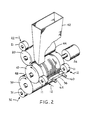
- FIGS 1 and 2 illustrate an apparatus for conducting a preferred process of this invention.
- the apparatus comprises a first pressurized roller system and a second pressurized roller system.
- pressurized roller system means two rollers in roll contact and exhibiting a nip zone pressure sufficient to provide compression of tobacco material which passes therethrough.
- the apparatus includes roller 10 which is a common roller to each of the first and second pressurized roller systems.
- the first roller system includes roller 10 and another roller 20 in roll contact with one another.
- roll contact is meant that the rollers each contact at a tangential point of the periphery of each roller; and such contact extends substantially along the length of each roller.
- Each of the rollers forming the first pressurized roller system are mounted such that the aforementioned roll contact of roller 10 with roller 20 is substantially maintained during operation.
- Force is applied to each of roller 10 and roller 20 by compression roller in roll contact with each of rollers 10 and 20, such as compression roller 11 and compression roller 21, respectively.
- the force is provided in a direction shown schematically by arrow 12 and arrow 22, respectively.
- the force can be provided to rollers 11 and 21 by force providing means 13 and force providing means 23, respectively, such as jack screws or hydraulic cylinders (shown in Figure 1).
- two compression rollers are positioned on each roller of the pressurized roller system and are positioned towards the end of the roller with which the compression rollers are in roll contact (as shown in Figure 2).
- each of the two such compression rollers have diameters and a combined longitudinal length less than that of the roller with which the compression rollers are in roll contact.
- the force providing means is positioned on each compression roller.
- the force providing means can be compression springs, tension springs, or the like.
- Each of rollers 10 and 20 are rotated in the direction indicated by the arrows within the rollers.
- the rollers are rotated in opposite directions relative to one another in order that the tobacco material can be passed through the nip of the rollers.
- Each of the rollers can be driven using a power source 26 (shown in Figure 2) such as a variable speed motor (e.g. an electric motor having from about 1 to about 5 horsepower) which turns the rollers by a series of drive gears (not shown).
- the rollers are supported by support means such as a frame (not shown) to a chassis (not shown).
- the second pressurized roller system includes roller 10 and another roller 30 in roll contact with one another.
- Each of the rollers forming the second pressurized roller system are mounted such that the aforementioned roll contact of roller 10 with roller 30 is substantially maintained during operation.
- Force is applied to each of roller 10 and roller 30 by compression rollers in roll contact with each of rollers 10 and 30 such as compression roller 11 and compression roller 31, respectively.
- the force is provided in a direction shown schematically by arrow 12 and arrow 32, respectively.
- the force can be provided to rollers 11 and 31 by force providing means 13 and force providing means 33, respectively, such as jack screws or hydraulic cylinders.
- Compression roller ⁇ 31 and force providing means 33 are positioned as are the compression rollers and force providing means described hereinbefore.
- the force providing means can be compression springs, tension springs, or the like.
- Each of rollers 10 and 30 are rotated in the direction indicated by the arrows within the rollers.
- the rollers are rotated in opposite directions relative to one another in order that the tobacco material can be passed through the nip of the rollers.
- Each of the rollers can be driven using a power source 26 (shown in Figure 2) which turns the rollers by a series of drive gears (not shown).
- the rollers are supported by support means such as a frame (not shown) to a chassis (not shown).
- Angle A which can be defined as that angle formed by the roll axis (i.e., the longitudinally extending axis) of each of rollers 20, 10 and 30, respectively.
- the value of angle A can depend upon a variety of factors including the diameters of the various rollers. Typically, angle A ranges from less than 180° to a limiting angle defined by the diameter of the rollers, and preferably ranges from about 90° to about 150°.
- roller 20 contains the series of grooves extending longitudinally along the roller wherein each groove extends about the periphery of the roller, and rollers 20 and 30 (which are each in roll contact with roller 10) have substantially smooth (i.e., non grooved) roller faces.
- rollers 20 and 30 each can have the previously described series of grooves extending longitudinally therealong, and roller 10 (which is in roll contact with each of rollers 20 and 30) can have a substantially smooth roller face.
- the roller having the series of grooves extending longitudinally therealong have those grooves positioned along the longitudinal length of the roller in the region between the compression rollers and in the region not in roll contact with the compression rollers.
- the forces between the rollers which typically are required can vary, but are those forces which are great enough to generate sufficient roller nip zone pressures in order to provide ultimately reclaimed (i.e., reconstituted) tobacco materials in a strand form or in a sheet-like form. That is, sufficient nip zone pressures are those sufficient to provide shearing, mixing, and forming of said tobacco material, and can be as great as is desired.
- forces between rollers of at least about 3,000 (5,254) and as great as about 10,000 (17,513) preferably about 4,000 (7,005) to about 6,000 (10,508) pounds per linear inch (Newtons per centimetre), are great enough to generate sufficient roller nip zone pressures.
- rollers are constructed of a metal material such as hardened carbon steel or hardened alloy steel.
- the sizes of the various rollers can vary.
- roller diameters range from about 3 inches (7.6cm) to about 8 inches (20.3cm) preferably about 6 inches (15.2cm) to about 8 inches (20.3cm); while roller lengths range from about 6 inches (15.2cm) to about 12 inches (30.5cm), preferably about 8 inches (20.3cm) to about 12 inches (30.5cm).
- Rollers forming the two roller systems can each have diameters which are equal, or the diameters of the various rollers can differ.
- Rotational roller speeds range, for example, from about 4 rpm to about 20 rpm.
- tobacco material 40 which preferably has been physically premixed using conventional means, itsfed by hopper 42 (which is shown as partially cut away in Figure 2) to feed zone 44 which feeds the tobacco material to the nip of rollers 10 and 20.
- the tobacco material can vary and typically includes tobacco dust, tobacco fines, scrap tobacco which is recovered from various processing stages and cigarette manufacture stages, scraps and/or sheets of wet formed reconstituted tobacco (for example in dry form), scraps and/or sheets of dry formed reconstituted tobacco, tobacco leaf stems, and tobacco stems and stalks.
- Various types of tobaccos and blends thereof can be employed.
- the structural strength providing amount of tobacco leaf stem material included in the tobacco material can vary, and depends upon a variety of factors including the amount and size of that leaf stem material which has a length and/or diameter greater than the width and depth of the roller grooves of the first roller system.
- the amount of leaf stem material is not so high as to provide an undesirable character such as undesirable taste characteristics to the resulting strand material.
- the amount of leaf stem material is at least that amount which is of a size that is capable of providing a desirable structural strength to the reclaimed tobacco material formed according to this invention.
- the amount of leaf stem material required is at least about 15 percent, preferably at least about 18 percent, based on the total weight of tobacco material which is employed.
- the amount of leaf stem material does not exceed about 60 percent, based on the total weight of tobacco material which is employed.
- the tobacco leaf stem material can be employed as is without further grinding, milling, pulping, treating with large amount of water, etc.
- the character of the tobacco leaf stem material is such that said stem material can provide a structural strength to the resulting reclaimed tobacco material.
- the stem material can provide a fibrous character to the resulting strand of reclaimed tobacco material. It is believed that the average size of the tobacco leaf stem material is an important factor in providing a reclaimed tobacco material of desirable structural strength.
- the average size of the tobacco leaf stem material can vary, but the length and/or diameter thereof is larger than the greatest width and depth of the grooves which extend about the periphery of the face of the first pressurized roller system.
- the average size of the tobacco leaf stem material which is employed in the process of this embodiment ranges from about 0.03 inch (0.8mm) to about 0.2 inch (5.1mm) in diameter, preferably from about 0.04 inch (1.0mm) to about 0.13 inch (3.3mm) in diameter.
- Typical tobacco leaf stem material which is employed ranges in length from about 0.25 inch (6.4mm) to about 4 inches (10 2mm), preferably from about 0.375 inch (9.5mm) to about 2 inches (51mm).
- the moisture content of the tobacco material which is employed can vary. Typically, a low amount of moisture content requires a relatively greater amount of force between rollers in order to provide reclaimed tobacco materials; while a high moisture content requires the undesirable and energy intensive drying processes attendant in conventional water based reconstituted tobacco processes.
- the tobacco material which is employed in the process of this embodiment exhibits a moisture content of at least about 14 weight percent, preferably at least about 15 weight percent; while the upper limit of the moisture content is less than about 30 weight percent, and typically is as great as about 25 weight percent, preferably as great as about 18 weight percent. It is believed that moisture imparts a softening of tobacco material as well as providing a material having a pliability sufficiently low to allow for the utilizattion of a desirable force during the mixing process. It is desirable that the moisture content not be overly high as to cause an undesirable pliability of fiber material of relatively poor tensile strength.
- the mixed and pre-formed tobacco material 46 which passes through and leaves the first pressurized roller system is fed into zone 48 which is a region capable of feeding the tobacco material to the second roller system.
- the tobacco material exiting the first roller system can have a tendency to stick to the rollers, and the material can be removed from the rollers (particularly roller 20 as shown in Figures 1 and 2) by scrape 50.
- Scrape 50 can be a series of needles, a comb-like configuration or a knife-like means such as a doctor blade positioned against the length of the face of the roller so as to remove (i.e., scrape) the tobacco material from the face of the roller. Most preferably, scrape 50 is positioned non-tangentially to the surface of the roller.
- scrape 50 is positioned against the face of roller 20 about 10° to about 45° along the surface of the roller relative to the center of the roller from the point at which rollers 10 and 20 meet in roll contact.
- the scrape is positioned substantially parallel (i.e., within an angle of about 15°) relative to the tangent of the rollers formed by the point of the roll contact of rollers 10 and 20.
- Scrape 50 is attached to the chassis or frame of the apparatus (not shown) in order to maintain the positioning thereof against the face of the roller.
- zone 48 can be employed as an auxiliary feed zone where tobacco material, particularly small particle size material such as tobacco dust and/or tobacco fines, can be added to the mixed and pre-formed tobacco material 46 exiting the first roller system into zone 48.
- tobacco material particularly small particle size material such as tobacco dust and/or tobacco fines
- the compressed, admixed tobacco material provided by passing the tobacco material through the first pressurized roller system is contacted with tobacco dust and/or tobacco fines in zone 48.
- Zone 48 can include a means 52 for directing tobacco material 46 in the second pressurized roller system.
- the tobacco material 46 in zone 48 which has been mixed and pre-formed under pressure in the first pressurized roller system is generally a macerated, ground or pressed tobacco material having some reconstituted tobacco character.
- Tobacco material 46 is further formed under pressure into the desired strand or sheet-like material by passing tobacco material 46 through a subsequent second pressurized roller system.
- roller 10 has the previously described series of grooves extending longitudinally therealong and is in roll contact with both of rollers 20 and 30.
- tobacco material 46 is passed through the nip of rollers 10 and 30.
- the tobacco material 54 exits the second roller and can be removed from the surface of roller using scrape 56.
- Scrape 56 is attached to the chassis or frame of the apparatus (not shown) in order to maintain the positioning thereof against the face of the roller.
- the tobacco material 54 can be directed from the apparatus by removal means 58 and then collected.
- Reconstituted tobacco material in strand form is provided through the use of scrape 56 having the form of needles 60 extending into each of the grooves of that roller having the series of grooves extending therealong (as shown in Figure 2).
- scrape 56 having the form of needles 60 extending into each of the grooves of that roller having the series of grooves extending therealong
- needles positioned so as to extend into the groove can tend to remove the tobacco material from the groove.
- Needles 60 are held in place by frame 62 (as shown in Figure 2).
- reconstituted tobacco material in sheet-like form is provided through the use of scrape 56 having the form of a doctor blade (not shown) positioned as are needles 60 extending along the face of the roller having the series of grooves extending therealong.
- Scrape 56 is most preferably positioned non-tangentially to the roller.
- scrape 56 is positioned against the face of roller 10 about 10° to about 30° along the surface of the roller relative to the center of the roller from the point at which rollers 10 and 30 meet in roll contact.
- the scrape is positioned substantially parallel (i.e., within an angle of about 15°) relative to the tangent of the rollers formed by the roll contact of rollers 10 and 30.
- Figure 3 illustrates a series of grooves 70 each having a top portion 72 and a bottom portion 74.
- the series of grooves extends longitudinally along a portion of a roller designated as roller 10.
- the grooves 70 can be incorporated into roller 10 by techniques such as machining using a suitable lathe.
- Each groove completely circumscribes roller 10.
- each groove has a shape substantially similar to the other grooves which extend around the roller.
- the grooves can extend about the roller in a circumferential fashion, a helical fashion, or the like.
- the grooves circumscribe the roller substantially transversely relative to the longitudinal axis of the roller.
- Top portion 72 can be, for example, pointed, or flattened (as illustrated in Figure 3).
- the top portion 72 When flattened, the top portion 72 typically ranges in width from about 0.010 inch (0.25mm) to about 0.015 inch (0.38mm). Generally, the flattened top portion 72 is narrow enough so as to not require excessive force in order to maintain roller contact in the pressurized roller system; while flattened top portion 72 is wide enough as to not deform to a substantial extent under typical roller pressures.
- Bottom portion 74 can be pointed, rounded, or flattened (as illustrated in Figure 3). When flattened, bottom portion 74 typically ranges in width from about 0.003 inch (0.08mm) to about 0.007 inch (0.18mm). Generally, bottom portion 74 is narrow enough so as to provide sufficient mixing action of the tobacco material.
- the mixing action is believed to be provided by the compression feeding performed by the relatively large size leaf stems which carry the tobacco particles into the grooves.
- Flattened bottom portion 74 is wide enough so as to permit the release of tobacco material from the surface region of the roller after processing.
- a bottom portion 74 which is overly narrow or pointed can tend to trap tobacco material in the groove and prevent release of the tobacco material therefrom.
- the depth d of the groove can vary and typically ranges from about 0.015 inch (0.38mm) to about 0.035 inch (0.89mm).
- the depth is defined as the radial distance between the bottom portion of the groove and the top portion of the groove.
- the greatest width w of the groove can vary and typically ranges from about 0.015 inch (0.38mm) to about 0.040 inch (1.0mm).
- the width is defined as the lateral distance measured across the groove.
- the pitch p of the groove can vary and depends upon a variety of factors including the type of tobacco material which is processed, the moisture content of said tobacco material, the leaf stem content of the tobacco material, the shape of the groove, and the like.
- the pitch is defined as that lateral distance from the center of top portion 72 to the center of the nearest adjacent top portion 72.
- a pitch of about 0.02 inch (i.e., about 1/50 inch or 0.51mm) to about 0.06 inch (i.e., about 1/16 inch or 1.5mm); preferably about 0.03 inch (i.e., about 1/32 inch or 0.76mm) is useful for most applications.
- the shape of groove 70 can vary and depends upon a variety of factors.
- each groove has a maximum width near the surface of the roller and a minimum width near the bottom of the groove.
- Each groove has sloped sides (i.e., non perpendicular to the roller face) and preferably each groove is generally "V" shaped.
- pressurized roller system having a roller comprising a series of grooves each having a sloping inner edge each groove circumscribing an angle A ⁇ of less than about 100°, can mix tobacco material suitably well; and a pressurized roller system having a roller comprising a series of grooves each having a sloping inner edge, each groove circumscribing an angle A ⁇ of greater than about 45°, can release processed tobacco material suitably well.
- the preferred angle A ⁇ is about 60° to about 90°, most preferably about 60°.
- the process of this embodiment employs first and second roller systems each having a grooved roller as described previously. It is believed that the shearing action provided by each pressurized roller system provides a breakdown of individual particles and fibers of tobacco material. Such a breakdown of particles and fibers is believed to provide a separation of natural binding materials from the particles and fibers, which natural binding materials can provide a binding action to the tobacco material in order to provide a resulting strand material. In addition, it is believed that shearing and mixing action provided by the pressurized roller system can provide a sufficient mechanical interlocking of fibers and particles, thus forming a type of matrix.
- a pressurized roller system containing a roller having a series of grooves having a size smaller than that of the tobacco leaf stem material is believed to provide a separation of leaf stem material, mixing and remixing of tobacco material, coalescing and agglomeration of tobacco material, and binding of tobacco material with natural binding materials of tobacco material.
- the reclaimed tobacco which is provided according to the process of this embodiment can be provided generally in the form of a strand.
- the tobacco material in the form of a strand exhibits a structural strength which approaches that of cut filler.
- strand as used herein is meant that the tobacco material is in a form wherein the length of said material is substantially greater than the width and thickness thereof.
- the thickness of the strand approximates that of tobacco leaf.
- the thickness of the strand ranges from about 0.005 inch (0.13mm) to about 0.040 inch (1.0mm) preferably from about 0.025 inch (0.64mm) to about 0.035 inch (0.89mm).
- the length of the strand can vary depending upon the means which is employed in forming the strand.
- the width can vary and typically approximates that of cut filler (i.e., most preferably about 32 cuts per inch or 13 cuts per centimetre).
- the thickness and width of the strand is most dependent upon the dimensions of the grooves of the rollers.
- the strand can be cut into lengths and employed as filler in the manufacture of cigarettes.
- the reclaimed tobacco which is provided according to the process of this embodiment can be provided generally in the form of a sheet.
- the tobacco material in the form of a sheet exhibits a structural strength which approaches that of tobacco leaf.
- sheet as used herein is meant that the tobacco material is in a form wherein the length and width thereof are substantially greater than the thickness thereof.
- the thickness of the sheet approximates that of tobacco leaf.
- the thickness of the sheet ranges from about 0.005 inch (0.13mm) to about 0.040 inch (1.0mm), preferably from about 0.005 inch (0.13mm) to about 0.015 inch (0.38mm).
- the length and width of the sheet can vary.
- the width of the sheet generally is determined by the length of the means for removing the reclaimed tobacco material from the roller face having the series of grooves of the second roller system.
- the sheet can be cut as in tobacco leaf or wet formed reconstituted tobacco material (e.g., in strips of about 32 cuts per inch or 13 cuts per centimetre) and employed as cut filler in the manufacture of cigarettes.
- Roller 20 is constructed of hardened carbon steel, has a substantially smooth surface, and has a diameter of 5 inches (12.7cm) and a roller face having a length of 8 inches (20.3cm).
- Roller 10 has a diameter of 5 inches (12.7cm) and is of similar length and construction to roller 20; however, roller 10 contains grooves extending in a circumferential fashion about the periphery of said roller 10.
- Roller 10 comprises a series of grooves extending 5 inches (12.7cm) longitudinally along the roller face, and the 1.5 inch (3.8mm) longitudinal distance along the roller face at each end of the roller is relatively smooth.
- Roller 10 is generally described in Figure 3.
- the depth d of the grooves is about 0.0155inch (0.394mm),the pitch p of each groove is about 0.03125inch (0.794mm) and the angle A ⁇ is about 60°.
- the top portion of each groove is flattened by a distance of about 0.01275 inch (0.324mm) and the bottom of each groove is flattened by a distance of about 0.006 inch (0.15mm).
- the rollers are operated using a variable speed drive using a variable speed 1.5 horsepower electric motor at a speed of about 4 rpm, and a nip zone pressure of about 5000 pounds per linear inch (8800 N/cm) is generated.
- Roller 30 is of similar size and construction to roller 20.
- Roller 30 is operated using a variable speed drive at a speed of 4 rpm, and nip zone pressure between each of roller 10 and roller 30 of 5000 pounds per linear inch (8800 N/cm) is generated.
- the angle A provided by the central axis of roller 20, roller 10 and roller 30, respectively, is 90°.
- Scrape 56 in the form of needles is positioned so as to remove the reclaimed tobacco material from roller 10.
- Force is provided to each of rollers 10, 20 and 30 by 2 compression rollers positioned in roll contact with each of rollers 10, 20, and 30.
- Each compression roller is positioned at one end of each of rollers 10, 20 and 30.
- the compression rollers are about 1 inch (2.54cm) in longitudinal length and about 2 inches (5.1cm) in diameter. Force is provided to the compression rollers by jack screws.
- a blend of scrap tobacco is provided.
- the blend is about 45 percent cut tobacco filler fines having an average particle diameter of less than 20 Tyler mesh, about 17 percent tobacco dust from a Molins MK9 Maker, and about 38 percent Winnower throw stems from a Molins MK9 Maker.
- the blend exhibits a moisture content of about 10 percent.
- a resultant blend is provided by contacting the blend with enough water to provide a blend exhibiting a 20 percent moisture level. The resultant blend is introduced into the apparatus and a reclaimed tobacco material in the form of strand is provided.
- the resulting strand has a generally triangular or trapezoidal shape and dimensions of about 1 inch (2.54cm) long, about 0.024 inch (0.61mm) thick, about 0.012 inch (0.30mm) to about 0.025 inch (0.64mm) wide.
- rollers 10, 20 and 30 have a diameter of about 4 inches (10.2cm) and are constructed from hardened carbon steel.
- the rollers each have a longitudinal length of about 4 inches (10.2cm).
- rollers 20 and 30 have substantially smooth roller faces.
- Roller 10 has a roller face having a series of grooves extending about 2 inches (5.1cm) along the longitudinal length of the roller and positioned on the roller such that roller face is substantially smooth near the ends of the roller.
- Each groove on roller 10 extends in a circumferential fashion about the periphery of the roller and is generally described in Figure 3.
- each groove The depth d of each groove is about 0.017 inch (0.43mm); the width of each groove is about 0.025 inch (0.64mm); the pitch p of each groove is about 0.036 inch (0.91mm); and the angle A ⁇ is about 60°.
- Each of rollers 20 and 30 are in roll contact with roller 10 and angle A provided by the central axis of roller 20, roller 10 and roller 30, respectively, is 150°.
- At both ends of each roller and in roll contact with each roller are positioned compression rollers.
- Each compression roller has a longitudinal length of 1 inch (2.54cm) and a diameter of 2 inches (5.1cm).
- Hydraulic cylinders connected to both compression rollers 11, and jack screws connected to compression rollers 21 and 31, provide nip zone pressures to each of the pressurized roller systems of greater than about 3000 pounds per linear inch (5300 N/cm).
- the apparatus is powered by 1 horsepower variable speed electric motor.
- the grooves of the roller 10 are positioned with removal means 56 in the form of needles.
- a blend of scrap tobacco as described in Example 1 is processed using the apparatus, and reconstituted tobacco in the form of strand is provided.
Landscapes
- Manufacture Of Tobacco Products (AREA)
- Paper (AREA)
- Cigarettes, Filters, And Manufacturing Of Filters (AREA)
Applications Claiming Priority (2)
| Application Number | Priority Date | Filing Date | Title |
|---|---|---|---|
| US06/809,456 US4646764A (en) | 1985-12-16 | 1985-12-16 | Process for providing roll reconstituted tobacco material |
| US809456 | 1985-12-16 |
Publications (2)
| Publication Number | Publication Date |
|---|---|
| EP0227422A2 true EP0227422A2 (fr) | 1987-07-01 |
| EP0227422A3 EP0227422A3 (fr) | 1989-01-11 |
Family
ID=25201386
Family Applications (1)
| Application Number | Title | Priority Date | Filing Date |
|---|---|---|---|
| EP86309837A Withdrawn EP0227422A3 (fr) | 1985-12-16 | 1986-12-16 | Procédé de récupération de tabac |
Country Status (7)
| Country | Link |
|---|---|
| US (1) | US4646764A (fr) |
| EP (1) | EP0227422A3 (fr) |
| JP (1) | JPS62146586A (fr) |
| CN (1) | CN86107969A (fr) |
| BR (1) | BR8606051A (fr) |
| CA (1) | CA1260349A (fr) |
| ES (1) | ES2002934A6 (fr) |
Cited By (6)
| Publication number | Priority date | Publication date | Assignee | Title |
|---|---|---|---|---|
| EP0232176A2 (fr) * | 1986-02-05 | 1987-08-12 | R.J. Reynolds Tobacco Company | Procédé pour fabriquer de la matière en tabac reconstitué |
| EP0233046A2 (fr) * | 1986-02-03 | 1987-08-19 | R.J. Reynolds Tobacco Company | Procédé de récupération de tabac |
| EP0269396A2 (fr) * | 1986-11-21 | 1988-06-01 | R.J. Reynolds Tobacco Company | Traitement d'une matière en tabac |
| CN104026726A (zh) * | 2014-07-02 | 2014-09-10 | 龙岩烟草工业有限责任公司 | 压梗机润辊系统及方法 |
| CN104382221A (zh) * | 2014-10-09 | 2015-03-04 | 红云红河烟草(集团)有限责任公司 | 一种烟梗加工制成梗丝的方法 |
| US11753750B2 (en) | 2018-11-20 | 2023-09-12 | R.J. Reynolds Tobacco Company | Conductive aerosol generating composite substrate for aerosol source member |
Families Citing this family (16)
| Publication number | Priority date | Publication date | Assignee | Title |
|---|---|---|---|---|
| US4730629A (en) * | 1986-03-17 | 1988-03-15 | R. J. Reynolds Tobacco Company | Process for providing tobacco extender material |
| US4702264A (en) * | 1986-08-11 | 1987-10-27 | R. J. Reynolds Tobacco Company | Tobacco leaf processing |
| US4768527A (en) * | 1987-01-23 | 1988-09-06 | R. J. Reynolds Tobacco Company | Tobacco material processing |
| US4867179A (en) * | 1987-10-14 | 1989-09-19 | R. J. Reynolds Tobacco Company | System and method for reclaiming and utilizing tobacco in the manufacture of cigarettes |
| US5584306A (en) * | 1994-11-09 | 1996-12-17 | Beauman; Emory | Reconstituted tobacco material and method of its production |
| DE102005006117B4 (de) * | 2005-02-10 | 2007-01-11 | British American Tobacco (Germany) Gmbh | Verarbeitung von Tabakmaterialien mit hohem Anteil an Tabakkleinteilen |
| CN101904558B (zh) * | 2010-07-23 | 2012-05-09 | 安徽中烟工业公司 | 一种辊压法烟草薄片的制造方法 |
| EP2654468A1 (fr) | 2010-12-23 | 2013-10-30 | Philip Morris Products S.a.s. | Tabac haché comprenant des tiges enroulées découpées |
| EP2617299A1 (fr) * | 2012-01-18 | 2013-07-24 | Delfortgroup AG | Papier rempli de particules de tabac |
| CN102599637B (zh) * | 2012-03-10 | 2014-10-22 | 广东中烟工业有限责任公司 | 一种烟草薄片的制备方法 |
| CN102657378A (zh) * | 2012-05-04 | 2012-09-12 | 云南昆船设计研究院 | 一种烟草打叶复烤生产中的烟梗预处理工艺 |
| RU2672640C2 (ru) * | 2014-06-16 | 2018-11-16 | Филип Моррис Продактс С.А. | Усиленное полотно восстановленного табака |
| JP7039883B2 (ja) * | 2016-12-01 | 2022-03-23 | デクセリアルズ株式会社 | 異方性導電フィルム |
| US10897925B2 (en) | 2018-07-27 | 2021-01-26 | Joseph Pandolfino | Articles and formulations for smoking products and vaporizers |
| US20200035118A1 (en) | 2018-07-27 | 2020-01-30 | Joseph Pandolfino | Methods and products to facilitate smokers switching to a tobacco heating product or e-cigarettes |
| US11712059B2 (en) | 2020-02-24 | 2023-08-01 | Nicoventures Trading Limited | Beaded tobacco material and related method of manufacture |
Citations (6)
| Publication number | Priority date | Publication date | Assignee | Title |
|---|---|---|---|---|
| US2845933A (en) * | 1954-05-28 | 1958-08-05 | Liggett & Myers Tobacco Co | Process of converting fragmented tobacco into coherent sheets |
| US3053259A (en) * | 1958-04-22 | 1962-09-11 | Lorillard Co P | Processing tobacco |
| US3424170A (en) * | 1963-12-06 | 1969-01-28 | Georg Grunwald | Process of forming reconstituted tobacco foils |
| US3709232A (en) * | 1969-12-15 | 1973-01-09 | Arenco Ab | Method for making tobacco webs and strings |
| US3865120A (en) * | 1970-11-12 | 1975-02-11 | Gerlach Gmbh E | Process for producing tobacco foils |
| US4164948A (en) * | 1976-01-23 | 1979-08-21 | Tamag Basel Ag | Method for making artificial tobacco and apparatus for performing said method |
Family Cites Families (5)
| Publication number | Priority date | Publication date | Assignee | Title |
|---|---|---|---|---|
| US1068403A (en) * | 1911-11-25 | 1913-07-22 | Louis Maier | Process for the production of artificial tobacco-leaves. |
| US2708175A (en) * | 1954-05-28 | 1955-05-10 | Max M Samfield | Composition of matter consisting chiefly of fragmented tobacco and galactomannan plant gum |
| US3209763A (en) * | 1961-04-05 | 1965-10-05 | Lorillard Co P | Method for making tobacco products |
| GB983928A (en) * | 1962-05-03 | 1965-02-24 | British American Tobacco Co | Improvements relating to the production of tobacco smoking materials |
| ZA747795B (en) * | 1973-12-20 | 1975-12-31 | Tamag Basel Ag | Smokable products, a process for their production and a device for carrying out the process |
-
1985
- 1985-12-16 US US06/809,456 patent/US4646764A/en not_active Expired - Fee Related
-
1986
- 1986-11-28 CN CN198686107969A patent/CN86107969A/zh active Pending
- 1986-12-09 BR BR8606051A patent/BR8606051A/pt unknown
- 1986-12-11 JP JP61293605A patent/JPS62146586A/ja active Pending
- 1986-12-15 ES ES8603428A patent/ES2002934A6/es not_active Expired
- 1986-12-15 CA CA000525282A patent/CA1260349A/fr not_active Expired
- 1986-12-16 EP EP86309837A patent/EP0227422A3/fr not_active Withdrawn
Patent Citations (6)
| Publication number | Priority date | Publication date | Assignee | Title |
|---|---|---|---|---|
| US2845933A (en) * | 1954-05-28 | 1958-08-05 | Liggett & Myers Tobacco Co | Process of converting fragmented tobacco into coherent sheets |
| US3053259A (en) * | 1958-04-22 | 1962-09-11 | Lorillard Co P | Processing tobacco |
| US3424170A (en) * | 1963-12-06 | 1969-01-28 | Georg Grunwald | Process of forming reconstituted tobacco foils |
| US3709232A (en) * | 1969-12-15 | 1973-01-09 | Arenco Ab | Method for making tobacco webs and strings |
| US3865120A (en) * | 1970-11-12 | 1975-02-11 | Gerlach Gmbh E | Process for producing tobacco foils |
| US4164948A (en) * | 1976-01-23 | 1979-08-21 | Tamag Basel Ag | Method for making artificial tobacco and apparatus for performing said method |
Cited By (9)
| Publication number | Priority date | Publication date | Assignee | Title |
|---|---|---|---|---|
| EP0233046A2 (fr) * | 1986-02-03 | 1987-08-19 | R.J. Reynolds Tobacco Company | Procédé de récupération de tabac |
| EP0233046A3 (fr) * | 1986-02-03 | 1989-01-25 | R.J. Reynolds Tobacco Company | Procédé de récupération de tabac |
| EP0232176A2 (fr) * | 1986-02-05 | 1987-08-12 | R.J. Reynolds Tobacco Company | Procédé pour fabriquer de la matière en tabac reconstitué |
| EP0232176A3 (fr) * | 1986-02-05 | 1989-01-25 | R.J. Reynolds Tobacco Company | Procédé pour fabriquer de la matière en tabac reconstitué |
| EP0269396A2 (fr) * | 1986-11-21 | 1988-06-01 | R.J. Reynolds Tobacco Company | Traitement d'une matière en tabac |
| EP0269396A3 (fr) * | 1986-11-21 | 1989-01-18 | R.J. Reynolds Tobacco Company | Traitement d'une matière en tabac |
| CN104026726A (zh) * | 2014-07-02 | 2014-09-10 | 龙岩烟草工业有限责任公司 | 压梗机润辊系统及方法 |
| CN104382221A (zh) * | 2014-10-09 | 2015-03-04 | 红云红河烟草(集团)有限责任公司 | 一种烟梗加工制成梗丝的方法 |
| US11753750B2 (en) | 2018-11-20 | 2023-09-12 | R.J. Reynolds Tobacco Company | Conductive aerosol generating composite substrate for aerosol source member |
Also Published As
| Publication number | Publication date |
|---|---|
| JPS62146586A (ja) | 1987-06-30 |
| CA1260349A (fr) | 1989-09-26 |
| ES2002934A6 (es) | 1988-10-01 |
| BR8606051A (pt) | 1987-09-15 |
| EP0227422A3 (fr) | 1989-01-11 |
| US4646764A (en) | 1987-03-03 |
| CN86107969A (zh) | 1987-07-01 |
Similar Documents
| Publication | Publication Date | Title |
|---|---|---|
| EP0227422A2 (fr) | Procédé de récupération de tabac | |
| US4787402A (en) | Process and apparatus for providing roll reconstituted tobacco material | |
| US4880018A (en) | Extruded tobacco materials | |
| EP0325476B1 (fr) | Procédé pour l'extrusion de matière de tabac | |
| US4730629A (en) | Process for providing tobacco extender material | |
| US4233996A (en) | Cutting leaf tobacco | |
| US4724850A (en) | Process for providing tobacco extender material | |
| EP0118981B1 (fr) | Procédé pour la production d'une matière à fumer à partir de déchets grossiers d'une machine à fabriquer les cigarettes et appareil y relatif | |
| US4702264A (en) | Tobacco leaf processing | |
| US4768527A (en) | Tobacco material processing | |
| US4053004A (en) | Helical head comminuting shear | |
| US4566470A (en) | Tobacco leaf processing | |
| US4754767A (en) | Tobacco material processing | |
| JPH0716907B2 (ja) | 切断機のナイフの改良 | |
| GB2131671A (en) | Tobacco leaf processing | |
| US3773267A (en) | Method and apparatus for the comminution of wood | |
| SU1210652A3 (ru) | Нож дл резки спрессованного табака на полосообразные волокна | |
| JPS6154394B2 (fr) | ||
| WO1980002101A1 (fr) | Procede de defibrage de cotes de tabac | |
| JPS5953954B2 (ja) | 製紙原材料用繊維の切断とフィブリル化を分離して行う紙料調製方法 | |
| JPH0655089A (ja) | シュレッダ | |
| JPS5444099A (en) | Method and apparatus for shredding leaf tobacco to tobacco for cigarette |
Legal Events
| Date | Code | Title | Description |
|---|---|---|---|
| PUAI | Public reference made under article 153(3) epc to a published international application that has entered the european phase |
Free format text: ORIGINAL CODE: 0009012 |
|
| AK | Designated contracting states |
Kind code of ref document: A2 Designated state(s): BE CH DE FR GB LI NL |
|
| PUAL | Search report despatched |
Free format text: ORIGINAL CODE: 0009013 |
|
| AK | Designated contracting states |
Kind code of ref document: A3 Designated state(s): BE CH DE FR GB LI NL |
|
| STAA | Information on the status of an ep patent application or granted ep patent |
Free format text: STATUS: THE APPLICATION IS DEEMED TO BE WITHDRAWN |
|
| 18D | Application deemed to be withdrawn |
Effective date: 19890103 |
|
| RIN1 | Information on inventor provided before grant (corrected) |
Inventor name: YOUNG, HARVEY JAMES Inventor name: LEONARD, GERARD EUGENE |