EP0227175B2 - Koksofentür und Koksofenbatterie mit solch einer Tür - Google Patents
Koksofentür und Koksofenbatterie mit solch einer Tür Download PDFInfo
- Publication number
- EP0227175B2 EP0227175B2 EP19860202263 EP86202263A EP0227175B2 EP 0227175 B2 EP0227175 B2 EP 0227175B2 EP 19860202263 EP19860202263 EP 19860202263 EP 86202263 A EP86202263 A EP 86202263A EP 0227175 B2 EP0227175 B2 EP 0227175B2
- Authority
- EP
- European Patent Office
- Prior art keywords
- door
- plug
- coking
- coke
- box construction
- Prior art date
- Legal status (The legal status is an assumption and is not a legal conclusion. Google has not performed a legal analysis and makes no representation as to the accuracy of the status listed.)
- Expired
Links
- 238000004939 coking Methods 0.000 claims description 62
- 238000010276 construction Methods 0.000 claims description 52
- 239000003245 coal Substances 0.000 claims description 23
- 239000002184 metal Substances 0.000 claims description 18
- 206010022000 influenza Diseases 0.000 claims description 14
- 239000011810 insulating material Substances 0.000 claims description 10
- 239000000571 coke Substances 0.000 claims description 5
- 238000009423 ventilation Methods 0.000 claims description 5
- 238000000926 separation method Methods 0.000 claims description 3
- 239000007789 gas Substances 0.000 description 44
- 230000008646 thermal stress Effects 0.000 description 4
- 239000011449 brick Substances 0.000 description 3
- 238000000034 method Methods 0.000 description 3
- OKTJSMMVPCPJKN-UHFFFAOYSA-N Carbon Chemical compound [C] OKTJSMMVPCPJKN-UHFFFAOYSA-N 0.000 description 2
- 229910002804 graphite Inorganic materials 0.000 description 2
- 239000010439 graphite Substances 0.000 description 2
- 238000009413 insulation Methods 0.000 description 2
- 239000012528 membrane Substances 0.000 description 2
- 238000007789 sealing Methods 0.000 description 2
- 230000000903 blocking effect Effects 0.000 description 1
- 230000006866 deterioration Effects 0.000 description 1
- 230000007613 environmental effect Effects 0.000 description 1
- 238000003912 environmental pollution Methods 0.000 description 1
- 230000002349 favourable effect Effects 0.000 description 1
- 239000012774 insulation material Substances 0.000 description 1
- 230000007774 longterm Effects 0.000 description 1
- 239000000463 material Substances 0.000 description 1
- 230000005855 radiation Effects 0.000 description 1
- 239000011819 refractory material Substances 0.000 description 1
- 230000003014 reinforcing effect Effects 0.000 description 1
Images


Classifications
-
- C—CHEMISTRY; METALLURGY
- C10—PETROLEUM, GAS OR COKE INDUSTRIES; TECHNICAL GASES CONTAINING CARBON MONOXIDE; FUELS; LUBRICANTS; PEAT
- C10B—DESTRUCTIVE DISTILLATION OF CARBONACEOUS MATERIALS FOR PRODUCTION OF GAS, COKE, TAR, OR SIMILAR MATERIALS
- C10B25/00—Doors or closures for coke ovens
- C10B25/02—Doors; Door frames
- C10B25/06—Doors; Door frames for ovens with horizontal chambers
Definitions
- the invention relates to a coke-oven door for a coking chamber of a battery of coke ovens, consisting of a door body carrying a door seal and a door plug which extends into the coking chamber when the door is closed, the door plug consisting of a generally closed metal box construction in which the side walls form on each side of the plug, when the door is closed, together with the side walls of the coking chamber, a vertical gas flue, each side wall of the box construction being shaped to recede from the side wall of the coking chamber so as to form, when the door is closed, in conjunction with the side wall of the coking chamber, the said vertical gas flue for passage of coke-oven gas, so that gas pressure on the seal during coking is reduced and in which the box, construction of the plug in the vertical direction of the door is formed from a plurality of elements, each connected to the door body.
- a coke-oven door of this type is known from WO-85/04180.
- This known coke-oven door has a closed metal plug in which the side walls are so shaped that gas flues are formed.
- the occurence of gas leakages through the door seal is effectively reduced with this coke-oven door in that high gas pressures are prevented by the passage of coke-oven gas through the gas flues to the space above the coal in the coking chamber, from where the process gas is led off from the coking chamber through so-called ascension pipes (standpipes).
- the door plug has, however, a short rectangular gap on the front through which considerable leakage of coal takes place into the gas flues, or if the gap is so narrow that there is no coal leakage, difficulties arise when the door is fitted.
- the door plug of the coke-oven door according to WO-85/04180 consists of two constructions along the direction of the coking chamber.
- the fastening of the two involves an internal assembly which can only be reached by widening the front wall of the door plug.
- the door plug design is complicated and is liable to thermal stresses.
- DE-A-2,219,516 also discloses a coke-oven door in which vertical gas flues are formed adjacent the seal, but the whole of the door plug construction is not shown.
- EP-A-28679 shows a door plug consisting of a plate which is held away from the door body by stanchions.
- a similar door plug is also shown in DE-A-3440311, in which, however, the plate is fashioned as an open box for the transport of coke-oven gas, which is also held away from the door body by stanchions. In both cases the space behind the front plate is seen as a large gas flue. Both these designs of door plug have the disadvantage of leakages of coking coal into the gas flue.
- a large gas flue of this type is favourable for precluding gas leakages through the door-sealing construction by the reduction of the pressure of the coke-oven gas by leading off the coke-oven gas, but it is not necessary because with the greatly improved effectiveness of present day sealing constructions brought about by environmental demands, smaller gas flues suffice.
- the object of the invention is to provide a coke-oven door of the type set out at the beginning, in which no or almost no leakages of coking coal arise and in which the elements can move unhindered in the longitudinal direction of the coke-oven door.
- the front portion of the side wall of the plug as seen in horizontal section extends over 30 to 70% of the total thickness of the door plug from front to rear, and the smallest separation, when the door is closed, between the side walls of the door plug and the coking chamber is not less than 8 mm more preferably not less than 10 mm. If the front portion of the plug side walls has a length of less than 30% of the plug thickness, there are coal leakages; if this length is more than 70%, the gas flues are too small. If the length and dimensions of the wedge-shaped gap formed in this way are such that coking coal gets into the gas flues, fouling and blocking of the gas flues might occur; yet while the door is being fitted, there should be considerable play between the door plug and its side walls.
- the door plug of the coke-oven door known from US-A-2993845, which is constructed as a metal box, solves the problem of graphite deposits on the surface of the conventional door plug made from refractory material.
- the door plug is closed which means that there is no or almost no transport of coke-oven gas through the inside of the door plug.
- This metal door plug has a tapered shape to facilitate putting the door into its closed position.
- a disadvantage of this coke-oven door is that gas leakages occur through the door seal. These gas leakages are not acceptable from the viewpoint of environmental pollution.
- the first cause of gas leakages is the high pressure of coking gas during coking. High gas pressure occurs especially at the commencement of coking at the lowest part of the coke-oven door.
- a second cause of gas leakages with the coke-oven door described above is that the door plug is too inflexible along the length of the coke-oven door, so that the door body distorts and as a result leakages of gas arise through the door seal.
- the door plug of the coke-oven door known from DE GM 77 17505 has an outer shape which provides for gas flues and which prevents leakage of coal from the coking chamber into the gas flues.
- the door plug consists however of refractory elements. Graphite deposits on the surface thereof are difficult to remove. The gaps between subsequent elements are filled with a refractory felt. The elements cannot move unhindered in the longitudinal direction of the door.
- the use in the present invention of a closed box construction for the door plug which encloses a substantial part of the space defined by the front face of the coking coal in the coking chamber, the side walls of the coking chamber and the door body, is essential.
- the door body is well insulated, and heat loss from the coke-oven battery is reduced.
- the coking coal is evenly coked and there are no cold spots at the front face of the coal.
- the upper end of the box construction of the plug is closed by a metal plate when the door is closed.
- the box construction is thus closed or nearly closed against transport of coke oven gas by shutting off at least its upper end. Passage of coke-oven gas through the interior of the box construction is undesirable, because the heat transfer to the coking coal during coking, especially to the coal near the door plug, can be disturbed. This can result in the coking ofthatcoal being retarded, and not being done in time. Moreover, such gas transport leads very quickly to fouling of the interior of the box construction, which is difficult to clean.
- the lower end of the box construction is also closed by a metal plate. An additional advantage is that the lower end of the box construction is stiffened by the metal plate, reducing deformation of the box construction.
- the box construction of the door plug is in the invention formed longitudinally (vertically) of a plurality of elements, each of which is connected to the door body.
- the door plug is fully flexible along the length of the coke-oven door, so that distortion of the elements by thermal stresses brings no or almost no force to bear on the door body, and thus distortion of the door body is avoided.
- the lower element has a reduced cross-section region at its upper end which is received in the lower end of the upper element.
- This telescopic or sleeve design frustrates any ingress of coal into the joint between the two elements. It appears that the sleeve design is durable and little susceptible to thermal stresses, because the elements can move unhindered in the longitudinal direction of the coke-oven door.
- the upper and lower ends of the elements of the box construction are preferably closed by metal plates.
- the elements can be hermetically sealed from the coking chamber, so that no gases and vapours can get into the interior of the elements via the joint between two elements and thus cannot give rise for instance to soiling of the insulation which is described below or to deterioration of the properties of this insulation.
- this ventilation means is a vent pipe, which is connected to the exterior air.
- An accompanying advantage of this is that measuring leads from measuring apparatus within the door plug can be led out through the vent pipe.
- the metal plates which close the box construction are subject to thermal stresses and thus can be a source of cracks in the door plug. Therefore the number of metal plates used in a door plug is a matter that can only be optimised after experience over the long term.
- the box construction of the plug has thermal insulating material arranged in its interior. Except when the insulating material is applied to the outside of the box construction, the insulating material need not be covered. In the case of hermetically sealed elements the insulating material cannot be fouled by tar products.
- the rear part of the box construction i.e. the part near the door body
- the coal near the door plug gets completely coked, while the door body is well insulated.
- good coking of the coal near the coke-oven door as described in the invention takes place by radiation in and around the door plug. For this reason the configuration and heat capacity of the door plug are of great importance.
- the insulating material is refractory felt which is attached by fastening means to rear wall portions of the box construction. In this way the weight of the door plug is further reduced.
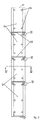
- the coke-oven door 1 shown in Fig. 1 consists of a door body 2 carrying a seal 3 on a membrane 15 and a door plug 4 which when the door is closed extends into the coal-filled coking chamber 5 of a battery of coke ovens 6.
- the door plug 4 is constructed as a metal box, with a thin wall 7, the interior of the box construction 8 being mainly hollow.
- Fig. 2 shows that the box construction of the plug consists of a plurality of elements 9, arranged vertically one above another and each mounted on the door body 2.
- Fig. 1 shows that the front portion 10 of each side wall 11 of the box construction when the door is closed forms a long narrow wedge-shaped gap 12 with the side walls 13 of the coking chamber 5, this gap 12 narrowing from the front corner towards the door body 2.
- the gap has at its narrowest place a width such that no or almost no leakage of coking coal from the coking chamber 5 past the narrowest place of the gap 12 can take place.
- each side wall 11 recedes from the coking chamber wall in the direction towards the door body 2 from the narrowest place of the gap 12, so that when the door is closed it forms, in conjunction with the side wall 13 of the coking chamber and with the door body 2 (i.e. with the membrane 15 of the seal 3 in the example illustrated), vertical gas flues 16 via which any high gas pressure arising during coking at the base of the door can be reduced. These flues 16 extend the whole height of the box construction and open at the top into the space above the coke.
- the box construction 8 is closed, which means that no or almost no gas movement can take place through the hollow box construction during the coking process.
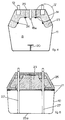
- Fig. 3 shows that in each pair of neighbouring elements 9 the upper end of the lower element is provided with a reduced cross-section portion 21 which is at least partly received by the lower end 22 of the upper element, thus forming a sleeve or telescopic construction, which avoids excessive rigidity of the box construction.
- the upper and lower ends of the box construction are closed by metal plates 17.
- both ends of each element 9 of the box construction are closed by metal plates 18 (see Fig. 3).
- Fig. 4 shows that each closed element 9 is fitted with ventilation means for its interior, in the form of a vent pipe 18a, which in this embodiment leads to the outside air.
- connection elements 19 are connected to the door body 2 by connecting elements 19.
- the embodiment of these connection elements shown in the figures i.e. plugs threaded at the ends, is adapted to the embodiment of door body shown in the figures, especially the seal 3,15. It is within the scope of the expert in this field to choose connecting elements which are appropriate to the design of the door body.
- Fig. 4 shows that the interior of the door plug is stiffened with a reinforcing beam 20.
- Figs. 4 and 5 show that the box construction contains insulating material 23, arranged in the rear part of the construction nearest to the door body.
- refractory felt is used, attached to the rear wall 25 and to the rear parts 14 of the side walls 11 by appropriate fastening means 24.
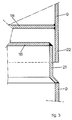
- FIG. 6 Asecond embodimentforthe door plug according to the invention is shown in Fig. 6, in which the part of the box construction consisting of the front wall 25a and the front portions 10 of the side wall 11 of the door plug is a separate hollow box construction which is attached by fastening means 27 to a metal brick holder 26 and to the door body (not shown).
- the metal brick holder forms a rear box construction and consists of a metal casing containing brick material and is filled with insulation material 23.
Landscapes
- Chemical & Material Sciences (AREA)
- Engineering & Computer Science (AREA)
- Materials Engineering (AREA)
- Oil, Petroleum & Natural Gas (AREA)
- Organic Chemistry (AREA)
- Coke Industry (AREA)
Claims (7)
Applications Claiming Priority (2)
| Application Number | Priority Date | Filing Date | Title |
|---|---|---|---|
| NL8503473 | 1985-12-18 | ||
| NL8503473A NL8503473A (nl) | 1985-12-18 | 1985-12-18 | Kooksovendeur. |
Publications (3)
| Publication Number | Publication Date |
|---|---|
| EP0227175A1 EP0227175A1 (de) | 1987-07-01 |
| EP0227175B1 EP0227175B1 (de) | 1989-10-11 |
| EP0227175B2 true EP0227175B2 (de) | 1992-12-23 |
Family
ID=19847025
Family Applications (1)
| Application Number | Title | Priority Date | Filing Date |
|---|---|---|---|
| EP19860202263 Expired EP0227175B2 (de) | 1985-12-18 | 1986-12-15 | Koksofentür und Koksofenbatterie mit solch einer Tür |
Country Status (3)
| Country | Link |
|---|---|
| EP (1) | EP0227175B2 (de) |
| DE (1) | DE3666228D1 (de) |
| NL (1) | NL8503473A (de) |
Family Cites Families (5)
| Publication number | Priority date | Publication date | Assignee | Title |
|---|---|---|---|---|
| GB173866A (en) * | 1920-10-08 | 1922-01-09 | Secure Castings Ltd | Improvements in or relating to coke oven doors and the like |
| US2571597A (en) * | 1944-08-22 | 1951-10-16 | Robert K Millard | Coke-oven buckstay structure |
| FR1230381A (fr) * | 1958-07-22 | 1960-09-15 | United States Steel Corp | Porte métallique à tampon pour four à coke |
| DE2157915A1 (de) * | 1971-11-23 | 1973-05-30 | Otto & Co Gmbh Dr C | Tuer fuer waagerechte verkokungsoefen |
| EP0028679B1 (de) * | 1979-11-08 | 1983-06-08 | WSW Planungs-GmbH | Koksofentür mit grossvolumigem Gassammelraum |
-
1985
- 1985-12-18 NL NL8503473A patent/NL8503473A/nl not_active Application Discontinuation
-
1986
- 1986-12-15 DE DE8686202263T patent/DE3666228D1/de not_active Expired
- 1986-12-15 EP EP19860202263 patent/EP0227175B2/de not_active Expired
Also Published As
| Publication number | Publication date |
|---|---|
| NL8503473A (nl) | 1987-07-16 |
| EP0227175A1 (de) | 1987-07-01 |
| DE3666228D1 (en) | 1989-11-16 |
| EP0227175B1 (de) | 1989-10-11 |
Similar Documents
| Publication | Publication Date | Title |
|---|---|---|
| US4749446A (en) | Horizontal coke-oven battery | |
| US9115313B2 (en) | Floor construction for horizontal coke ovens | |
| CA1038323A (en) | Refractory shapes and jamb structure of coke oven battery heating wall | |
| US4118284A (en) | Plug-type coke oven door | |
| US4414072A (en) | Door for coking chamber of coke-oven battery | |
| EP0227175B2 (de) | Koksofentür und Koksofenbatterie mit solch einer Tür | |
| AU2008333601B2 (en) | Device for expelling the contents of coke chamber ovens having a low degree of heat exchange | |
| US4336108A (en) | Closure assembly for horizontal-chamber coking ovens | |
| HU212171B (en) | Partitioned wall for compartment furnace | |
| US4713148A (en) | Light construction plug for coke oven doors | |
| US5395485A (en) | Reactor chamber door for large-scale coking reactors | |
| US4793900A (en) | Universal coke oven door liner | |
| US2275400A (en) | Coke oven door | |
| JPS61118493A (ja) | コークス炉の操作方法 | |
| US3214353A (en) | Jamb structure for coke oven batteries | |
| US5735917A (en) | Method of promoting carbonization in the door region of a coke oven and oven door therefor | |
| US3881995A (en) | Method and apparatus for sealing a coking chamber | |
| US4197163A (en) | Coke oven door | |
| US2571597A (en) | Coke-oven buckstay structure | |
| EP0107878B1 (de) | Koksofenbatterie | |
| US3503852A (en) | Horizontal coke oven having thickened extreme ends firing channel walls | |
| EP0065328B1 (de) | Verfahren zur Reparatur einer Koksofenbatterie und dazu verwendbare Wand | |
| JPH108061A (ja) | コークス炉の炉蓋 | |
| CA1309373C (en) | Universal coke oven door liner | |
| JPS61155489A (ja) | コークス炉蓋用炉蓋栓 |
Legal Events
| Date | Code | Title | Description |
|---|---|---|---|
| PUAI | Public reference made under article 153(3) epc to a published international application that has entered the european phase |
Free format text: ORIGINAL CODE: 0009012 |
|
| 17P | Request for examination filed |
Effective date: 19861215 |
|
| AK | Designated contracting states |
Kind code of ref document: A1 Designated state(s): BE DE FR NL |
|
| 17Q | First examination report despatched |
Effective date: 19880725 |
|
| GRAA | (expected) grant |
Free format text: ORIGINAL CODE: 0009210 |
|
| AK | Designated contracting states |
Kind code of ref document: B1 Designated state(s): BE DE FR NL |
|
| ET | Fr: translation filed | ||
| REF | Corresponds to: |
Ref document number: 3666228 Country of ref document: DE Date of ref document: 19891116 |
|
| PGFP | Annual fee paid to national office [announced via postgrant information from national office to epo] |
Ref country code: NL Payment date: 19891231 Year of fee payment: 4 |
|
| PLBI | Opposition filed |
Free format text: ORIGINAL CODE: 0009260 |
|
| 26 | Opposition filed |
Opponent name: RUHRKOHLE AG Effective date: 19900710 |
|
| NLR1 | Nl: opposition has been filed with the epo |
Opponent name: RUHRKOHLE AG |
|
| PG25 | Lapsed in a contracting state [announced via postgrant information from national office to epo] |
Ref country code: NL Effective date: 19910701 |
|
| NLV4 | Nl: lapsed or anulled due to non-payment of the annual fee | ||
| PGFP | Annual fee paid to national office [announced via postgrant information from national office to epo] |
Ref country code: FR Payment date: 19911107 Year of fee payment: 6 |
|
| PGFP | Annual fee paid to national office [announced via postgrant information from national office to epo] |
Ref country code: DE Payment date: 19911121 Year of fee payment: 6 |
|
| PGFP | Annual fee paid to national office [announced via postgrant information from national office to epo] |
Ref country code: BE Payment date: 19911127 Year of fee payment: 6 |
|
| PUAH | Patent maintained in amended form |
Free format text: ORIGINAL CODE: 0009272 |
|
| STAA | Information on the status of an ep patent application or granted ep patent |
Free format text: STATUS: PATENT MAINTAINED AS AMENDED |
|
| 27A | Patent maintained in amended form |
Effective date: 19921223 |
|
| AK | Designated contracting states |
Kind code of ref document: B2 Designated state(s): BE DE FR NL |
|
| PG25 | Lapsed in a contracting state [announced via postgrant information from national office to epo] |
Ref country code: BE Effective date: 19921231 |
|
| EN3 | Fr: translation not filed ** decision concerning opposition | ||
| PG25 | Lapsed in a contracting state [announced via postgrant information from national office to epo] |
Ref country code: FR Effective date: 19930514 |
|
| BERE | Be: lapsed |
Owner name: HOOGOVENS GROEP B.V. Effective date: 19921231 |
|
| PG25 | Lapsed in a contracting state [announced via postgrant information from national office to epo] |
Ref country code: DE Effective date: 19930901 |
|
| REG | Reference to a national code |
Ref country code: FR Ref legal event code: ST |