EP0226900A2 - Plural-stage mill - Google Patents
Plural-stage mill Download PDFInfo
- Publication number
- EP0226900A2 EP0226900A2 EP86116844A EP86116844A EP0226900A2 EP 0226900 A2 EP0226900 A2 EP 0226900A2 EP 86116844 A EP86116844 A EP 86116844A EP 86116844 A EP86116844 A EP 86116844A EP 0226900 A2 EP0226900 A2 EP 0226900A2
- Authority
- EP
- European Patent Office
- Prior art keywords
- mill
- grinding
- mill according
- stages
- rotor
- Prior art date
- Legal status (The legal status is an assumption and is not a legal conclusion. Google has not performed a legal analysis and makes no representation as to the accuracy of the status listed.)
- Granted
Links
Images
Classifications
-
- B—PERFORMING OPERATIONS; TRANSPORTING
- B02—CRUSHING, PULVERISING, OR DISINTEGRATING; PREPARATORY TREATMENT OF GRAIN FOR MILLING
- B02C—CRUSHING, PULVERISING, OR DISINTEGRATING IN GENERAL; MILLING GRAIN
- B02C23/00—Auxiliary methods or auxiliary devices or accessories specially adapted for crushing or disintegrating not provided for in preceding groups or not specially adapted to apparatus covered by a single preceding group
- B02C23/18—Adding fluid, other than for crushing or disintegrating by fluid energy
- B02C23/24—Passing gas through crushing or disintegrating zone
- B02C23/28—Passing gas through crushing or disintegrating zone gas moving means being integral with, or attached to, crushing or disintegrating element
-
- B—PERFORMING OPERATIONS; TRANSPORTING
- B02—CRUSHING, PULVERISING, OR DISINTEGRATING; PREPARATORY TREATMENT OF GRAIN FOR MILLING
- B02C—CRUSHING, PULVERISING, OR DISINTEGRATING IN GENERAL; MILLING GRAIN
- B02C13/00—Disintegrating by mills having rotary beater elements ; Hammer mills
- B02C13/14—Disintegrating by mills having rotary beater elements ; Hammer mills with vertical rotor shaft, e.g. combined with sifting devices
-
- B—PERFORMING OPERATIONS; TRANSPORTING
- B02—CRUSHING, PULVERISING, OR DISINTEGRATING; PREPARATORY TREATMENT OF GRAIN FOR MILLING
- B02C—CRUSHING, PULVERISING, OR DISINTEGRATING IN GENERAL; MILLING GRAIN
- B02C13/00—Disintegrating by mills having rotary beater elements ; Hammer mills
- B02C13/26—Details
- B02C13/288—Ventilating, or influencing air circulation
-
- B—PERFORMING OPERATIONS; TRANSPORTING
- B02—CRUSHING, PULVERISING, OR DISINTEGRATING; PREPARATORY TREATMENT OF GRAIN FOR MILLING
- B02C—CRUSHING, PULVERISING, OR DISINTEGRATING IN GENERAL; MILLING GRAIN
- B02C13/00—Disintegrating by mills having rotary beater elements ; Hammer mills
- B02C13/26—Details
- B02C13/30—Driving mechanisms
-
- B—PERFORMING OPERATIONS; TRANSPORTING
- B02—CRUSHING, PULVERISING, OR DISINTEGRATING; PREPARATORY TREATMENT OF GRAIN FOR MILLING
- B02C—CRUSHING, PULVERISING, OR DISINTEGRATING IN GENERAL; MILLING GRAIN
- B02C13/00—Disintegrating by mills having rotary beater elements ; Hammer mills
- B02C13/14—Disintegrating by mills having rotary beater elements ; Hammer mills with vertical rotor shaft, e.g. combined with sifting devices
- B02C2013/145—Disintegrating by mills having rotary beater elements ; Hammer mills with vertical rotor shaft, e.g. combined with sifting devices with fast rotating vanes generating vortexes effecting material on material impact
Abstract
Description
Die Erfindung bezieht sich auf eine Mühle mit mehreren Mahlstufen, bestehend aus einem im wesentlichen zylindrischen, allen Mahlstufen gemeinsamen Stator, einem mit einer Vielzahl von in mehreren Stufen übereinander angeordneten Mahlplatten ausgerüsteten Rotor sowie einer Fördereinrichtung für ein Trägergas, das die Mühle mit dem Mahlgut durchsetzt.The invention relates to a mill with several grinding stages, consisting of an essentially cylindrical stator common to all grinding stages, a rotor equipped with a plurality of grinding plates arranged one above the other in several stages, and a conveying device for a carrier gas which passes through the mill with the grinding stock .
Eine Mühle dieser Art ist aus der Druckschrift "Ultra-Rotor" der Firma "Altenburger Maschinen" bekannt. Das Zerkleinerungsprinzip dieser mit Luft als Trägergas arbeitenden Mühle beruht darauf, daß die Mahlgutpartikel innerhalb der Vielzahl von Luftwirbeln, die von den Mahlplatten erzeugt werden, auf eine hohe Geschwindigkeit beschleunigt werden und vorzugsweise gegenseitige Stöße ausführen. Diese gegenseitigen Stöße führen zum Auseinanderbrechen der Teilchen. Nur ein geringer Teil der Zerkleinerungsvorgänge erfolgt durch das Zusammentreffen der Mahlgutteilchen mit den feststehenden oder rotierenden Maschinenteilen. Dadurch, daß die gegenseitigen Zusammenstöße der Partikel im Luftstrom überwiegen,*wird eine besonders schonende Feinstverkleinerung des Mahlgutes erreicht.A mill of this type is known from the publication "Ultra-Rotor" from the company "Altenburger Maschinen". The crushing principle of this mill, which works with air as the carrier gas, is based on the fact that the regrind particles within the large number of air vortices generated by the grinding plates are accelerated to a high speed and preferably execute mutual impacts. These mutual impacts break the particles apart. Only a small part of the shredding processes occurs when the regrind particles meet the stationary or rotating machine parts. Because the mutual collisions of the particles in the air flow predominate, * a particularly gentle, very fine reduction of the ground material is achieved.
Bewährt hat sich dieses Zerkleinerungsprinzip insbesondere beim Mahlen von temperaturempfindlichen Produkten. Dadurch, daß sich das Produkt ständig innerhalb turbulenter Luftströme befindet, wird die bei der Zerkleinerung unvermeidbar entstehende Wärme sofort abgeführt. Gleichzeitig wird auch gegebenenfalls vorhandene Feuchtigkeit von der Luft aufgenommen, so daß zusätzlich eine intensive Trocknung feuchter Mahlgüter erreicht werden kann.This shredding principle has proven itself particularly when grinding temperature-sensitive products. Thereby, that the product is constantly in turbulent air flows, the heat unavoidably generated during the comminution is immediately dissipated. At the same time, any moisture that may be present is also absorbed by the air, so that intensive drying of moist regrind can additionally be achieved.
Die genannte Druckschrift läßt erkennen, daß der Luftführung und der Luftmengensteuerung in Mühlen der betroffenen Art hohe Bedeutung zukommt. Eine ausreichende Luftzufuhr muß sichergestellt sein, damit überhitzungen sowohl des Produktes als auch der Maschine nicht eintreten.The cited document shows that the air routing and the air volume control in mills of the type concerned is of great importance. Adequate air supply must be ensured so that overheating of both the product and the machine does not occur.
Der vorliegenden Erfindung liegt die Aufgabe zugrunde, eine Mühle der eingangs erwähnten Art zu schaffen, bei der eine ausreichende Luftzufuhr stets sichergestellt ist. Außerdem soll eine Verbesserung der Mahlleistung erreicht werden.The present invention has for its object to provide a mill of the type mentioned, in which an adequate air supply is always ensured. In addition, the grinding performance should be improved.
Erfindungsgemäß wird diese Aufgabe dadurch gelöst, daß den Mahlstufen eine (weitere) Gasfördereinrichtung vorgelagert ist. Insbesondere dann, wenn diese Gasfördereinrichtung den Mahlstufen unmittelbar vorgelagert ist, treten Betriebszustände mit zu geringer Luftzufuhr und die dadurch bewirkten überhitzungen nicht mehr auf.According to the invention, this object is achieved in that the grinding stages are preceded by a (further) gas delivery device. In particular, if this gas delivery device is located upstream of the grinding stages, operating conditions with insufficient air supply and the overheating caused thereby no longer occur.
Eine vorteilhafte Weiterbildung der Erfindung ist dadurch gekennzeichnet, daß die Gasfördereinrichtung einen zentralen Gas- und Mahlguteintritt sowie einen radialen Gas- und Mahlgutauslass aufweist. Der besondere Vorteil dieser Lösung besteht darin, daß sich das Mahlgut bereits vor dem Eintritt in die eigentlichen Mahlstufen gleichmäßig auf dem Umfang der Mühle verteilt. Die Nachteile des üblichen, seitlich-tangentialen Mahlguteintritts in die Mühle, welche die Maschinenteile einseitig stark belasten, bestehen nicht mehr.An advantageous development of the invention is characterized in that the gas delivery device has a central gas and regrind inlet and a radial gas and regrind outlet. The particular advantage of this solution is that the regrind is evenly distributed over the circumference of the mill before entering the actual grinding stages. The disadvantages of the usual, tangential, grist entry into the mill, which put heavy loads on one side of the machine, no longer exist.
Als besonders vorteilhaft hat sich erwiesen, wenn die erfindungsgemäße Gasfördereinrichtung als einstufiges Radialgebläse ausgebildet ist und wenn das Gebläserad mit den Mahlstufen auf der Rotorwelle, und zwar unmittelbar unterhalb der ersten Mahlstufe, befestigt ist. Radiälgebläse dieser Art zeichnen sich durch eine besonders hohe Leistung aus. Überraschenderweise hat sich gezeigt, daß ein Radialgebläse-rad auch dazu geeignet ist, das Mahlgut vom axial-nahen Eintritt zum radialen Auslass zu fördern und dadurch gleichmäßig auf den Umfang der Mühle, also unmittelbar vor dem Eintritt in die.erste Mahlstufe, zu verteilen.It has proven to be particularly advantageous if the gas delivery device according to the invention is designed as a single-stage radial fan and if the impeller with the grinding stages is fastened to the rotor shaft, specifically immediately below the first grinding stage. Centrifugal fans of this type are characterized by a particularly high performance. Surprisingly, it has been shown that a radial fan wheel is also suitable for conveying the regrind from the axially close inlet to the radial outlet and thereby distributing it evenly over the circumference of the mill, i.e. immediately before entering the first grinding stage.
Weitere Vorteile und Einzelheiten der Erfindung sollen anhand von in den Figuren 1 bis 7 dargestellten Ausführungsbeispielen erläutert werden.Further advantages and details of the invention will be explained on the basis of the exemplary embodiments illustrated in FIGS. 1 to 7.
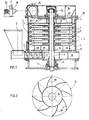
Bei der in Figur 1 dargestellten Mühle sind der Stator bzw. das Statorgehäuse mit 1, der Rotor allgemein mit 2, der Speisetrichter mit 3 und die Speiseschnecke mit 4 bezeichnet.In the mill shown in FIG. 1, the stator or the stator housing is denoted by 1, the rotor generally by 2, the feed hopper by 3 and the feed screw by 4.
Die Mühle ist mit fünf übereinanderliegenden Mahlstufen 5 ausgerüstet. Jede Mahlstufe wird von einer auf dem Umfang einer Kreisscheibe 6 befestigten Vielzahl (z.B. ca. 50) befestigten Mahlplatten 7 gebildet. Die Mahlplatten 7 erstrecken sich jeweils radial und parallel zur Drehachse 8 des Rotors. Die die Mahlplatten 7 tragenden Scheiben 6 sind an den Nabenabschnitten 9 befestigt, die ihrerseits mit der Welle 11 des Rotors 2 verbunden sind. Die Welle 11 ist oberhalb und unterhalb des Rotors 2 in Lagern 12, 13 gehaltert. Unterhalb des unteren Lagers 12 befindet sich der nicht dargestellte Antrieb.The mill is equipped with five
Auf der Rotorwelle 11 ist zusätzlich das Radialgebläserad 15 befestigt, und zwar unmittelbar unterhalb der untersten Mahlstufe 5. Sein axialer Eintritt 16 ist nach unten gerichtet und einem Raum 17 zugewandt, in den der Zuführungsschacht für das Mahlgut mit der Schnecke 4 und ein Luftzuführungskanal 18 münden. Zur besseren Führung des Mahlgutes und der Luft bei ihrem Eintritt in das Gebläserad 15 ist ein den Eintritt 16 umgebender Rand 19 vorgesehen, der sich senkrecht zur Ebene des Rades 15 in Richtung des zentral gelegenen Raumes 17 erstreckt.On the
Oberhalb der Mahlstufen 5 ist auf der Welle 11 eine Scheibe 21 befestigt, an deren Umfang die Sichterfinger 22 befestigt sind. Oberhalb der Sichterfinger 22 befindet sich eine im wesentlichen kreisringförmige Austrittsöffnung 23, an die sich der Ringkanal 24 und die Auslaßöffnung 25 anschließen. Die Auslaßöffnung 25 ist entweder direkt oder über nicht dargestellte Abscheider mit dem Ventilator 26 verbunden, dessen Motor mit 27 bezeichnet ist.Above the
In Figur 2 ist das Gebläserad 15 nochmals dargestellt. Es weist insgesamt acht nach hinten gekrümmte Schaufeln 28 auf.In Figure 2, the
Während des Betriebs der Mühle gelangen das Mahlgut und die sowohl für den Transport als auch für das Mahlen erforderliche Luftmenge in den Raum 17 und treten von dort aus axial-zentral in das Gebläserad 15 ein. Innerhalb des sich schnell drehenden Gebläserades 15 werden das Mahlgut und die Luft in Rotation versetzt und radial nach außen gefördert. Dadurch wird eine gleichmäßige Verteilung des Mahlgutes auf die Statorinnenwand bewirkt, dem sich ein ebenfalls gleichmäßiges Hochsteigen des Mahlgutes durch die Mahlstufen 5 anschließt. Gleichzeitig hat das Gebläserad 15 eine auflösende Wirkung, d.h., gegebenenfalls vorhandene Mahlgutklumpen werden zerschlagen. Produkt und Luft durchsetzen danach die Mahlstufen 5. Ausreichend fein gemahlenes Gut ist in der Lage, mit der Trägerluft durch die rotierenden Sichterfinier hindurchzutreten. Durch den Kanal 24 und die Auslaßöffnung 25 verlassen das Mahlgut-Luftgemisch die Mühle 1 und werden anschließend in den nicht dargestellten Abscheidern voneinander getrennt. Von den Sichterfingern zurückgehaltenes Mahlgut verläßt die Mühle durch die überlaufklappe 29 und wird zum Mahlguteintritt zurückgeführt.During the operation of the mill, the ground material and the amount of air required for both transport and grinding enter the
Bei der dargestellten Mühle bewirken das Gebläserad 15 und der Ventilator 26 die Förderung des Trägergases und damit die Förderung des Mahlgutes. Die Förderleistung des Gebläses 15 entspricht der Drehzahl des Rotors 2, verändert sich also bei konstanter Rotordrehzahl nicht. Ist entsprechend einer vorteilhaften Weiterbildung der Erfindung die Drehzahl des Motors 27 und damit die Leistung des Ventilators 26 regelbar, dann kann damit Einfluß auf die Verweilzeit des Produktes im Bereich der Mahlstufen 5 genommen werden. Auch die Anpassung der zum Transport eines Produktes erforderlichen Trägergas-Strömungsverhältnisse, die von vielen Eigenschaften des zu mahlenden Produktes, z.B. seinem spezifischen Gewicht, abhängen, ist mit Hilfe des regelbaren Ventilators 26 besonders einfach.In the mill shown, the
Hat z.B. ein Produkt ein hohes spezifisches Gewicht, dann ist der obere Ventilator 26 auf eine hohe Förderleistung einzustellen, damit eine sichere Förderung des schweren Produkts gewährleistet ist.For example, if a product has a high specific weight, then the
Ist das Produkt feucht und soll die Feuchtigkeit während des Mahlprozesses verdampft werden, dann ist es zweckmäßig, den oberen Ventilator 26 zu drosseln. Dadurch wird die Verweilzeit des Luft-Material-Gemisches in der Mühle erhöht, so daß die gewünschte Trocknung während der Vermahlung eintritt. Die Trocknungsleistung kann noch dadurch erhöht werden, daß der Mühle 1 über den Kanal 18 Heißluft zugeführt wird.If the product is moist and the moisture is to be evaporated during the grinding process, it is expedient to throttle the
Auch bei der Verarbeitung schwer mahlbarer Produkte, z.B. mit Faser-Charakter, ist der obere Ventilator zu drosseln, damit die gewünschte Mahlwirkung besser erzielt werden kann.Even when processing products that are difficult to grind, e.g. with fiber character, the upper fan must be throttled so that the desired grinding effect can be achieved better.
Bei der Verarbeitung von Produkten, die eine besonders schonende Mahlbehandlung erfordern, ist mit niedrigen Temperaturen zu fahren. Dieses kann dadurch erreicht werden, daß mit möglichst viel Luft gearbeitet wird. In Anwendungsfällen dieser Art ist deshalb die Förderleistung des oberen Ventilators 26 zu erhöhen.When processing products that require a particularly gentle grinding treatment, it is necessary to drive at low temperatures. This can be achieved by working with as much air as possible. In applications of this type, the delivery rate of the
Weiterhin ist es im Rahmen der vorliegenden Erfindung zweckmäßig, den oberhalb des Rotors 2 befindlichen Fingersichter mit einem eigenen Antrieb auszurüsten, so daß die Drehzahl des Fingersichters unabhängig von der Drehzahl des Rotors 2 einstellbar ist. Diese Maßnahme ermöglicht nicht nur eine Einflußnahme auf die Korngröße des Produkts; sie erlaubt auch die Anpassung des Mahlvorgangs an die Produkteigenschaften. Soll z.B, ein spezifisch leichtes Produkt besonders fein und besonders schonend gemahlen werden, dann ist mit einem starken Trägergasstrom und besonders hoher Drehzahl des Fingersichters zu arbeiten. Der starke Trägergasstrom hält die Temperatur des Mahlgutes niedrig. Er hat aber auch die Wirkung, daß das Gut die Mühle besonders schnell durchsetzt, also nicht ausreichend fein gemahlen wird. Der schnelldrehende Fingersichter läßt deshalb das Produkt nicht aus der Mühle austreten. Es wird zum Mühleneintritt zurückgeführt. In dieser Zeit unterliegt es einer Mahlpause, so daß es sich weiter abkühlt, bevor es erneut dem Mahlprozess unterworfen wird.Furthermore, it is expedient in the context of the present invention, the finger sifter located above the
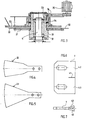
Figur 3 zeigt eine Ausführungsform für einen separaten Fingersichter-Antrieb. Dazu ist dem oberen Ende der Welle 11 der nur zum Teil dargestellten Mühle 1 eine Hülse 31 zugeordnet, die über die Lager 32, 33 auf der Welle 11 drehbar gehaltert ist. Außerhalb der Hülse 31 ist ein weiteres Lager 34 vorgesehen, über das sich die Hülse 31 im Mühlengehäuse abstützt. Die Hülse 31 ist dadurch unabhängig von der rotierenden Welle 11 drehbar gelagert.Figure 3 shows an embodiment for a separate finger classifier drive. For this purpose, a
Das untere Ende der Hülse 31 ragt in das Mühlengehäuse hinein und trägt dort die Scheibe 21 mit den Sichterfingern 22. Sie durchsetzt die Wandung des Mühlengehäuses und ist darin mit im einzelnen nicht näher bezeichneten Dichtringen abgedichtet. Außerhalb der Mühle ragt sie so weit hervor, daß sie mit einem regelbaren Antriebsmotor 35 über Riemen 36 koppelbar ist.The lower end of the
Üblicherweise haben die Finger 22 eine stabförmige Gestalt. Infolge ihrer radialen Anordnung nimmt deshalb der zwischen den Fingern befindliche Spalt in radialer Richtung zu. Um eine in radialer Richtung etwa gleichbleibende Spaltbreite zu erzielen, ist es im Rahmen der Erfindung zweckmäßig, Sichterfinger zu verwenden, deren Breite in radialer Richtung zunimmt. Ausführungsbeispiele dafür sind in den Figuren 4 und 5 dargestellt. Mit Sichterfingern dieser Art kann ein vorteilhafter Einfluß auf die Wirkung des Fingersichters, z.B. eine Vergleichmäßigung der Sichterwirkung, genommen werden.The
In den Figuren 6 und 7 ist eine in vorteilhafter Weise weitergebildete Mahlplatte 7 dargestellt. Sie weist in der Mitte ihrer Laufseite einen Einschnitt 41 auf. Oberhalb und unterhalb dieses Einschnittes 41 sind die laufseitigen Abschnitte 42 und 43 in entgegengesetzter Richtung abgeknickt. Mahlplatten dieser Art haben überraschenderweise eine erhebliche Verbesserung der Mahlleistung zur Folge. Die innerhalb der Mahlkammern befindlichen, aus Luft und Mahlgut bestehenden Wirbel werden durch diese Maßnahme gebrochen, so daß eine Verbesserung des Mahleffektes eintritt.FIGS. 6 and 7 show a
Claims (18)
Priority Applications (1)
| Application Number | Priority Date | Filing Date | Title |
|---|---|---|---|
| AT86116844T ATE65191T1 (en) | 1985-12-07 | 1986-12-03 | MILL WITH SEVERAL GRINDING LEVELS. |
Applications Claiming Priority (2)
| Application Number | Priority Date | Filing Date | Title |
|---|---|---|---|
| DE3543370 | 1985-12-07 | ||
| DE19853543370 DE3543370A1 (en) | 1985-12-07 | 1985-12-07 | MILL WITH SEVERAL GRINDINGS |
Related Child Applications (2)
| Application Number | Title | Priority Date | Filing Date |
|---|---|---|---|
| EP19890113826 Division EP0347948A3 (en) | 1985-12-07 | 1986-12-03 | Plural-stage mill |
| EP89113826.5 Division-Into | 1989-07-27 |
Publications (3)
| Publication Number | Publication Date |
|---|---|
| EP0226900A2 true EP0226900A2 (en) | 1987-07-01 |
| EP0226900A3 EP0226900A3 (en) | 1988-06-22 |
| EP0226900B1 EP0226900B1 (en) | 1991-07-17 |
Family
ID=6287950
Family Applications (2)
| Application Number | Title | Priority Date | Filing Date |
|---|---|---|---|
| EP19890113826 Withdrawn EP0347948A3 (en) | 1985-12-07 | 1986-12-03 | Plural-stage mill |
| EP86116844A Expired - Lifetime EP0226900B1 (en) | 1985-12-07 | 1986-12-03 | Plural-stage mill |
Family Applications Before (1)
| Application Number | Title | Priority Date | Filing Date |
|---|---|---|---|
| EP19890113826 Withdrawn EP0347948A3 (en) | 1985-12-07 | 1986-12-03 | Plural-stage mill |
Country Status (5)
| Country | Link |
|---|---|
| US (1) | US4747550A (en) |
| EP (2) | EP0347948A3 (en) |
| AT (1) | ATE65191T1 (en) |
| DE (2) | DE3543370A1 (en) |
| ES (1) | ES2023804B3 (en) |
Cited By (5)
| Publication number | Priority date | Publication date | Assignee | Title |
|---|---|---|---|---|
| WO1997026994A1 (en) * | 1996-01-23 | 1997-07-31 | Rudolf Engel | Device for treating composite components |
| EP0796660A1 (en) * | 1996-03-21 | 1997-09-24 | Altenburger Maschinen Jäckering GmbH | Method and device for fabricating ultrafine powders |
| WO1998051413A1 (en) * | 1997-05-12 | 1998-11-19 | Bayer Aktiengesellschaft | Microeddy mill and method for drying and deagglomerating powdery materials |
| WO1999061157A1 (en) * | 1998-05-27 | 1999-12-02 | Altenburger Maschinen Jäckering GmbH | Mill drying of cellulose derivatives, especially methylcellulose |
| DE102008049339A1 (en) | 2008-09-29 | 2010-04-01 | Pallmann Maschinenfabrik Gmbh & Co. Kg | Device for processing feedstock |
Families Citing this family (62)
| Publication number | Priority date | Publication date | Assignee | Title |
|---|---|---|---|---|
| DE3811910C2 (en) * | 1988-04-09 | 1997-04-10 | Mahltechnik Goergens Gmbh | Mill and method for grinding and drying a moist product simultaneously |
| GB2225522B (en) * | 1988-07-01 | 1992-09-30 | Alexander Stephen Anderson | Surface abrasive treatment of small objects |
| US5110059A (en) * | 1989-11-30 | 1992-05-05 | Titmas James A | Solid waste shredder |
| US4957794A (en) * | 1990-01-02 | 1990-09-18 | E. I. Dupont De Nemours And Company | Aramid fluff |
| US5084136A (en) * | 1990-02-28 | 1992-01-28 | E. I. Du Pont De Nemours And Company | Dispersible aramid pulp |
| US5171402A (en) * | 1990-02-28 | 1992-12-15 | E. I. Du Pont De Nemours And Company | Dispersible aramid pulp |
| DE4200827C2 (en) * | 1992-01-15 | 1997-09-04 | Jackering Altenburger Masch | Method and device for detecting plastic or rubber from a waste mixture |
| US5695130A (en) * | 1992-07-01 | 1997-12-09 | Csendes; Ernest | Method and apparatus for the dry grinding of solids |
| DE4228114A1 (en) * | 1992-08-25 | 1994-03-03 | Jackering Altenburger Masch | Process and device for the production of wheat flour |
| US5429783A (en) * | 1994-04-19 | 1995-07-04 | E. I. Du Pont De Nemours And Company | Making fiberballs |
| SI9400384A (en) * | 1994-10-07 | 1996-04-30 | Karel Ferlez | Universal mill |
| DE19506817A1 (en) * | 1995-02-27 | 1996-08-29 | Jackering Altenburger Masch | Centrifugal plate for grinder |
| US5826807A (en) * | 1995-04-17 | 1998-10-27 | Csendes; Ernest | Method and apparatus for comminuting of solid particles |
| US5850977A (en) * | 1995-04-17 | 1998-12-22 | Csendes; Ernest | Method and apparatus for comminuting solid particles |
| DE29515434U1 (en) * | 1995-09-27 | 1995-11-23 | Mahltechnik Goergens Gmbh | Micro vortex mill |
| DE29515433U1 (en) * | 1995-09-27 | 1995-11-30 | Mahltechnik Goergens Gmbh | Micro vortex mill |
| US5732894A (en) * | 1995-11-09 | 1998-03-31 | Sheahan; Richard T. | Micronization apparatus and method |
| US5740971A (en) * | 1995-11-17 | 1998-04-21 | Hsu; Wu-Heng | Apparatus for recycling synthetic leather |
| DE19601594C2 (en) * | 1996-01-18 | 1998-07-23 | Fritsch Gmbh | Method and device for comminuting materials, in particular for sample preparation for analysis |
| EP0835881B2 (en) † | 1996-10-14 | 2004-12-29 | Wolff Walsrode Ag | Process for preparing methylcellulose powder with special granulometric distribution |
| DE19715772C1 (en) * | 1997-04-16 | 1998-07-02 | Otto Herrmann | Plastic waste recovery plant |
| DE19723705C1 (en) * | 1997-06-06 | 1999-01-28 | Pallmann Kg Maschf | Mill for products of different origins |
| US6325306B1 (en) | 1997-10-22 | 2001-12-04 | Material Recovery Of North America, Inc. | Variable size reduction apparatus and process |
| FI105571B (en) * | 1998-01-14 | 2000-09-15 | Juha Vesa | A device for forming fiber balls from elongated fibers traveling with an air stream |
| DE19901305A1 (en) | 1999-01-15 | 2000-07-20 | Starck H C Gmbh Co Kg | Process for the production of hard metal mixtures |
| DE19920225B4 (en) * | 1999-05-03 | 2007-01-04 | Ecco Gleittechnik Gmbh | Process for the production of reinforcing and / or process fibers based on vegetable fibers |
| DE19962049C2 (en) * | 1999-12-22 | 2003-02-27 | Babcock Bsh Gmbh | Whirlwind Mill |
| DE10009411A1 (en) | 2000-02-28 | 2001-08-30 | Wolff Walsrode Ag | Process for the preparation of pulverulent water-soluble cellulose derivatives using a steam / inert gas mixture or steam / air mixture as transport and heat transfer gas |
| DE10009409A1 (en) | 2000-02-28 | 2001-08-30 | Wolff Walsrode Ag | Production of water-soluble cellulose derivatives as fine powder, for use as e.g. paint binders or thickeners, involves dissolution or swelling in water and drying with heat transfer-carrier gas in a high-speed rotary impact mill |
| AU2003257409A1 (en) * | 2002-08-28 | 2004-03-19 | Jm Engineering A/S | Apparatus and method for making fibre balls |
| DE10248174C1 (en) * | 2002-10-16 | 2003-11-13 | Nabaltec Gmbh | Flame-retardant thermoplastic, thermoset or thermosetting and/or elastomeric polymer composition, for producing coated electrical wire or cable by extrusion, contains aluminum hydroxide with specified properties as flame retardant |
| CN1929925B (en) * | 2004-03-23 | 2012-07-04 | 杨富茂 | High turbulence mill and its bi-negative pressure turbine |
| US7708216B2 (en) * | 2004-03-23 | 2010-05-04 | Fumao Yang | High turbulence mill and bi-negative pressure turbine thereof |
| DE102004014258C5 (en) * | 2004-03-24 | 2010-09-16 | Hosokawa Alpine Ag | Mill with interchangeable blow bars |
| CN100391613C (en) * | 2005-02-07 | 2008-06-04 | 缪文生 | Classifying sand breaker with double booster |
| CN100391614C (en) * | 2005-02-07 | 2008-06-04 | 缪文生 | Classifying sand breaker with double booster |
| ATE518902T1 (en) | 2005-05-12 | 2011-08-15 | Akzo Nobel Nv | METHOD FOR GRINDING CELLULOSE ETHER |
| DE102005032248B4 (en) * | 2005-07-09 | 2009-04-23 | Tronox Pigments Gmbh | Titanium dioxide pigment production using an air vortex mill |
| DE102005046207B4 (en) * | 2005-09-28 | 2014-12-24 | Get Hamburg Gmbh | Device for crushing debris |
| DE102005055563A1 (en) * | 2005-11-22 | 2007-05-24 | Altenburger Maschinen Jäckering GmbH | Air vortex mill for the milling drying of a flowable product and method for operating this mill |
| AU2007352535A1 (en) * | 2006-06-21 | 2008-12-04 | Martinswerk Gmbh | Process for producing magnesium hydroxide |
| AT507856B1 (en) * | 2009-02-03 | 2011-09-15 | Starlinger & Co Gmbh | DEVICE FOR CRUSHING PLASTIC |
| US7954740B2 (en) * | 2009-03-12 | 2011-06-07 | Rosace International Co., Ltd. | Pressure differential nano grinding and dispersing assembly |
| DE102009020714A1 (en) | 2009-05-11 | 2010-11-18 | Pallmann Maschinenfabrik Gmbh & Co Kg | Device for processing feedstock |
| DE102009034880A1 (en) | 2009-07-27 | 2011-02-24 | Altenburger Maschinen Jäckering GmbH | Use of a plastic-containing feedstock for cement kilns |
| EP2516122B1 (en) | 2009-12-22 | 2016-02-17 | Green-Gum Rubber Recycle Ltd. | Method and apparatus for rubber grinding and reclaiming |
| DE202012001821U1 (en) | 2012-02-22 | 2012-04-19 | Kai Neubauer | Milling plate, cutting plate or the like for a mill or crusher |
| DE102013110352A1 (en) * | 2013-09-19 | 2015-03-19 | Pms Handelskontor Gmbh | comminution device |
| JP6463096B2 (en) * | 2014-11-26 | 2019-01-30 | 株式会社スギノマシン | Raw material crusher |
| CN104815716B (en) * | 2015-04-17 | 2017-04-12 | 武汉凯迪工程技术研究总院有限公司 | High-pressure flour mill |
| JP6317392B2 (en) * | 2015-05-07 | 2018-04-25 | 株式会社 西村機械製作所 | Rice flour production equipment |
| DE102015007435A1 (en) | 2015-06-15 | 2016-12-15 | Pallmann Maschinenfabrik Gmbh & Co. Kg | Device and grinding tool for crushing feed |
| CN105413811A (en) * | 2016-01-04 | 2016-03-23 | 李新中 | Multistage crusher |
| EP3192377B1 (en) | 2016-01-14 | 2018-07-25 | Tessenderlo Group NV/SA | Method for producing partly hydrolyzed keratinaceous material |
| CN105728147B (en) * | 2016-03-07 | 2018-05-08 | 钟文虎 | Counter-impact flow pulverizer structure and pulverizer |
| HUE051673T2 (en) | 2018-01-22 | 2021-03-29 | Tessenderlo Group Nv | Improved method for producing blood meal |
| CN108940451B (en) * | 2018-06-25 | 2020-12-01 | 承德宏伟活性炭有限公司 | Gas treatment system for activated carbon production |
| EP3966254A1 (en) | 2019-05-06 | 2022-03-16 | Nouryon Chemicals International B.V. | Structuring agents |
| GB2597640A (en) * | 2020-06-10 | 2022-02-09 | Maelgwyn Mineral Services Ltd | A mineral liberation machine |
| EP3984372A1 (en) | 2020-10-14 | 2022-04-20 | Tessenderlo Group NV | Improved method for producing highly digestible hydrolyzed keratinaceous material |
| WO2023165936A1 (en) | 2022-03-01 | 2023-09-07 | Haarslev Industries A/S | Method for providing a dried hydrolysed material |
| WO2024056582A1 (en) | 2022-09-15 | 2024-03-21 | Haarslev Industries A/S | Process for producing dried fish meal |
Citations (5)
| Publication number | Priority date | Publication date | Assignee | Title |
|---|---|---|---|---|
| US2319629A (en) * | 1942-05-25 | 1943-05-18 | Gruendler Crusher & Pulverizer | Shredder blade |
| US2963230A (en) * | 1954-06-30 | 1960-12-06 | Microcyclomat Co | Dry material pulverizer with integral classifier |
| FR1282573A (en) * | 1960-11-02 | 1962-01-27 | Prvni Brnenska Strojirna Zd Y | Fan crusher |
| US3071330A (en) * | 1958-11-18 | 1963-01-01 | Altenburger Maschinen G M B H | Apparatus for fine grinding |
| CH450875A (en) * | 1965-06-14 | 1968-04-30 | Sturtevant Mill Co | Method and device for grinding granular material and for air classification of the ground product |
Family Cites Families (4)
| Publication number | Priority date | Publication date | Assignee | Title |
|---|---|---|---|---|
| US2561388A (en) * | 1945-08-20 | 1951-07-24 | Microcyclomat Co | Classifier units for friable material pulverizers |
| US2752097A (en) * | 1951-03-03 | 1956-06-26 | Microcyclomat Co | Method and apparatus for the production of fine and ultrafine particles |
| DE2707395A1 (en) * | 1977-02-21 | 1978-08-24 | Heinz Jaeger | SPRING ROLLER MILL |
| US4478371A (en) * | 1982-01-07 | 1984-10-23 | Williams Patent Crusher And Pulverizer Company | Fuel grinding apparatus |
-
1985
- 1985-12-07 DE DE19853543370 patent/DE3543370A1/en not_active Withdrawn
-
1986
- 1986-05-16 US US06/863,935 patent/US4747550A/en not_active Expired - Fee Related
- 1986-12-03 ES ES86116844T patent/ES2023804B3/en not_active Expired - Lifetime
- 1986-12-03 EP EP19890113826 patent/EP0347948A3/en not_active Withdrawn
- 1986-12-03 DE DE8686116844T patent/DE3680305D1/en not_active Expired - Fee Related
- 1986-12-03 AT AT86116844T patent/ATE65191T1/en active
- 1986-12-03 EP EP86116844A patent/EP0226900B1/en not_active Expired - Lifetime
Patent Citations (5)
| Publication number | Priority date | Publication date | Assignee | Title |
|---|---|---|---|---|
| US2319629A (en) * | 1942-05-25 | 1943-05-18 | Gruendler Crusher & Pulverizer | Shredder blade |
| US2963230A (en) * | 1954-06-30 | 1960-12-06 | Microcyclomat Co | Dry material pulverizer with integral classifier |
| US3071330A (en) * | 1958-11-18 | 1963-01-01 | Altenburger Maschinen G M B H | Apparatus for fine grinding |
| FR1282573A (en) * | 1960-11-02 | 1962-01-27 | Prvni Brnenska Strojirna Zd Y | Fan crusher |
| CH450875A (en) * | 1965-06-14 | 1968-04-30 | Sturtevant Mill Co | Method and device for grinding granular material and for air classification of the ground product |
Cited By (9)
| Publication number | Priority date | Publication date | Assignee | Title |
|---|---|---|---|---|
| WO1997026994A1 (en) * | 1996-01-23 | 1997-07-31 | Rudolf Engel | Device for treating composite components |
| US6065697A (en) * | 1996-01-23 | 2000-05-23 | Engel; Rudolf | Apparatus for treating composite elements |
| EP0796660A1 (en) * | 1996-03-21 | 1997-09-24 | Altenburger Maschinen Jäckering GmbH | Method and device for fabricating ultrafine powders |
| US5984212A (en) * | 1996-03-21 | 1999-11-16 | Altenburger Maschinen Jackering Gmbh | Method and apparatus for production of extremely fine powder |
| WO1998051413A1 (en) * | 1997-05-12 | 1998-11-19 | Bayer Aktiengesellschaft | Microeddy mill and method for drying and deagglomerating powdery materials |
| WO1999061157A1 (en) * | 1998-05-27 | 1999-12-02 | Altenburger Maschinen Jäckering GmbH | Mill drying of cellulose derivatives, especially methylcellulose |
| DE102008049339A1 (en) | 2008-09-29 | 2010-04-01 | Pallmann Maschinenfabrik Gmbh & Co. Kg | Device for processing feedstock |
| US8267341B2 (en) | 2008-09-29 | 2012-09-18 | Pallmann Maschinenfabrik Gmbh & Co. Kg | Device for processing feedstock |
| DE102008049339B4 (en) | 2008-09-29 | 2020-07-16 | Pallmann Maschinenfabrik Gmbh & Co. Kg | Device for processing feed material |
Also Published As
| Publication number | Publication date |
|---|---|
| DE3543370A1 (en) | 1987-06-11 |
| US4747550A (en) | 1988-05-31 |
| EP0226900A3 (en) | 1988-06-22 |
| EP0347948A2 (en) | 1989-12-27 |
| DE3680305D1 (en) | 1991-08-22 |
| ATE65191T1 (en) | 1991-08-15 |
| EP0347948A3 (en) | 1990-12-19 |
| EP0226900B1 (en) | 1991-07-17 |
| ES2023804B3 (en) | 1992-02-16 |
Similar Documents
| Publication | Publication Date | Title |
|---|---|---|
| EP0226900B1 (en) | Plural-stage mill | |
| DE2535979C3 (en) | Disk mill | |
| DE2136652A1 (en) | Jet mill | |
| DE1782775C3 (en) | ||
| EP0374491A2 (en) | Sifter | |
| DE3638915C2 (en) | ||
| DE1936269A1 (en) | Hammer mill | |
| DE19520325C2 (en) | Classifier mill | |
| DE3630920C1 (en) | Device for drying solid material discharged from a centrifuge | |
| EP0946304A1 (en) | Blade mill for grinding plastic material | |
| DE3837757C2 (en) | ||
| AT227515B (en) | Grinding device with controlled feed and controlled and classifying discharge of the ground material | |
| DE2629745C2 (en) | Spiral air classifier | |
| US3038672A (en) | Pulverizer classifier | |
| DE863284C (en) | Grinding classifier | |
| DE19839137C1 (en) | Roller mill with rotary sieve | |
| DE3590172C2 (en) | ||
| DE19834896A1 (en) | Centrifugal mill with adjustable particle size output has one or more milling stages removed and replaced by sieves | |
| DE4101343C1 (en) | ||
| DE1288888B (en) | Device for grinding lumpy goods | |
| EP0534483B1 (en) | Centrifugal separator with turbine | |
| DE2153236A1 (en) | MILL | |
| DE2104967C (en) | Centrifugal separator | |
| AT111257B (en) | ||
| DE2917595C2 (en) | Drum chipper with discharge chute |
Legal Events
| Date | Code | Title | Description |
|---|---|---|---|
| PUAI | Public reference made under article 153(3) epc to a published international application that has entered the european phase |
Free format text: ORIGINAL CODE: 0009012 |
|
| AK | Designated contracting states |
Kind code of ref document: A2 Designated state(s): AT BE CH DE ES FR GB GR IT LI NL SE |
|
| PUAL | Search report despatched |
Free format text: ORIGINAL CODE: 0009013 |
|
| AK | Designated contracting states |
Kind code of ref document: A3 Designated state(s): AT BE CH DE ES FR GB GR IT LI NL SE |
|
| 17P | Request for examination filed |
Effective date: 19880708 |
|
| 17Q | First examination report despatched |
Effective date: 19890216 |
|
| RAP1 | Party data changed (applicant data changed or rights of an application transferred) |
Owner name: ALTENBURGER MASCHINEN JAECKERING GMBH |
|
| GRAA | (expected) grant |
Free format text: ORIGINAL CODE: 0009210 |
|
| AK | Designated contracting states |
Kind code of ref document: B1 Designated state(s): AT BE CH DE ES FR GB GR IT LI NL SE |
|
| PG25 | Lapsed in a contracting state [announced via postgrant information from national office to epo] |
Ref country code: SE Effective date: 19910717 Ref country code: GR Free format text: LAPSE BECAUSE OF FAILURE TO SUBMIT A TRANSLATION OF THE DESCRIPTION OR TO PAY THE FEE WITHIN THE PRESCRIBED TIME-LIMIT Effective date: 19910717 |
|
| REF | Corresponds to: |
Ref document number: 65191 Country of ref document: AT Date of ref document: 19910815 Kind code of ref document: T |
|
| REF | Corresponds to: |
Ref document number: 3680305 Country of ref document: DE Date of ref document: 19910822 |
|
| ITF | It: translation for a ep patent filed |
Owner name: DE DOMINICIS & MAYER S.R.L. |
|
| ET | Fr: translation filed | ||
| GBT | Gb: translation of ep patent filed (gb section 77(6)(a)/1977) | ||
| PG25 | Lapsed in a contracting state [announced via postgrant information from national office to epo] |
Ref country code: LI Effective date: 19911231 Ref country code: CH Effective date: 19911231 Ref country code: AT Effective date: 19911231 |
|
| REG | Reference to a national code |
Ref country code: ES Ref legal event code: FG2A Ref document number: 2023804 Country of ref document: ES Kind code of ref document: B3 |
|
| PLBE | No opposition filed within time limit |
Free format text: ORIGINAL CODE: 0009261 |
|
| STAA | Information on the status of an ep patent application or granted ep patent |
Free format text: STATUS: NO OPPOSITION FILED WITHIN TIME LIMIT |
|
| 26N | No opposition filed | ||
| REG | Reference to a national code |
Ref country code: CH Ref legal event code: PL |
|
| PGFP | Annual fee paid to national office [announced via postgrant information from national office to epo] |
Ref country code: GB Payment date: 19921202 Year of fee payment: 7 |
|
| PGFP | Annual fee paid to national office [announced via postgrant information from national office to epo] |
Ref country code: ES Payment date: 19921203 Year of fee payment: 7 |
|
| PGFP | Annual fee paid to national office [announced via postgrant information from national office to epo] |
Ref country code: BE Payment date: 19921211 Year of fee payment: 7 |
|
| PGFP | Annual fee paid to national office [announced via postgrant information from national office to epo] |
Ref country code: FR Payment date: 19921221 Year of fee payment: 7 |
|
| PGFP | Annual fee paid to national office [announced via postgrant information from national office to epo] |
Ref country code: DE Payment date: 19921228 Year of fee payment: 7 |
|
| PGFP | Annual fee paid to national office [announced via postgrant information from national office to epo] |
Ref country code: NL Payment date: 19921231 Year of fee payment: 7 |
|
| PG25 | Lapsed in a contracting state [announced via postgrant information from national office to epo] |
Ref country code: GB Effective date: 19931203 |
|
| PG25 | Lapsed in a contracting state [announced via postgrant information from national office to epo] |
Ref country code: BE Effective date: 19931231 |
|
| BERE | Be: lapsed |
Owner name: ALTENBURGER MASCHINEN JACKERING G.M.B.H. Effective date: 19931231 |
|
| PG25 | Lapsed in a contracting state [announced via postgrant information from national office to epo] |
Ref country code: NL Effective date: 19940701 |
|
| GBPC | Gb: european patent ceased through non-payment of renewal fee |
Effective date: 19931203 |
|
| NLV4 | Nl: lapsed or anulled due to non-payment of the annual fee | ||
| PG25 | Lapsed in a contracting state [announced via postgrant information from national office to epo] |
Ref country code: FR Effective date: 19940831 |
|
| PG25 | Lapsed in a contracting state [announced via postgrant information from national office to epo] |
Ref country code: DE Effective date: 19940901 |
|
| REG | Reference to a national code |
Ref country code: FR Ref legal event code: ST |
|
| PG25 | Lapsed in a contracting state [announced via postgrant information from national office to epo] |
Ref country code: ES Free format text: LAPSE BECAUSE OF NON-PAYMENT OF DUE FEES Effective date: 19941204 |
|
| REG | Reference to a national code |
Ref country code: ES Ref legal event code: FD2A Effective date: 19950112 |
|
| PG25 | Lapsed in a contracting state [announced via postgrant information from national office to epo] |
Ref country code: IT Free format text: LAPSE BECAUSE OF NON-PAYMENT OF DUE FEES;WARNING: LAPSES OF ITALIAN PATENTS WITH EFFECTIVE DATE BEFORE 2007 MAY HAVE OCCURRED AT ANY TIME BEFORE 2007. THE CORRECT EFFECTIVE DATE MAY BE DIFFERENT FROM THE ONE RECORDED. Effective date: 20051203 |