EP0226489A1 - Selbstfahrender Stuhl für Behinderte mit einer automatischen Aufrichtvorrichtung - Google Patents
Selbstfahrender Stuhl für Behinderte mit einer automatischen Aufrichtvorrichtung Download PDFInfo
- Publication number
- EP0226489A1 EP0226489A1 EP86402478A EP86402478A EP0226489A1 EP 0226489 A1 EP0226489 A1 EP 0226489A1 EP 86402478 A EP86402478 A EP 86402478A EP 86402478 A EP86402478 A EP 86402478A EP 0226489 A1 EP0226489 A1 EP 0226489A1
- Authority
- EP
- European Patent Office
- Prior art keywords
- support
- tracks
- supports
- linked
- self
- Prior art date
- Legal status (The legal status is an assumption and is not a legal conclusion. Google has not performed a legal analysis and makes no representation as to the accuracy of the status listed.)
- Withdrawn
Links
Images


Classifications
-
- A—HUMAN NECESSITIES
- A61—MEDICAL OR VETERINARY SCIENCE; HYGIENE
- A61G—TRANSPORT, PERSONAL CONVEYANCES, OR ACCOMMODATION SPECIALLY ADAPTED FOR PATIENTS OR DISABLED PERSONS; OPERATING TABLES OR CHAIRS; CHAIRS FOR DENTISTRY; FUNERAL DEVICES
- A61G5/00—Chairs or personal conveyances specially adapted for patients or disabled persons, e.g. wheelchairs
- A61G5/06—Chairs or personal conveyances specially adapted for patients or disabled persons, e.g. wheelchairs with obstacle mounting facilities, e.g. for climbing stairs, kerbs or steps
- A61G5/061—Chairs or personal conveyances specially adapted for patients or disabled persons, e.g. wheelchairs with obstacle mounting facilities, e.g. for climbing stairs, kerbs or steps for climbing stairs
-
- A—HUMAN NECESSITIES
- A61—MEDICAL OR VETERINARY SCIENCE; HYGIENE
- A61G—TRANSPORT, PERSONAL CONVEYANCES, OR ACCOMMODATION SPECIALLY ADAPTED FOR PATIENTS OR DISABLED PERSONS; OPERATING TABLES OR CHAIRS; CHAIRS FOR DENTISTRY; FUNERAL DEVICES
- A61G5/00—Chairs or personal conveyances specially adapted for patients or disabled persons, e.g. wheelchairs
- A61G5/06—Chairs or personal conveyances specially adapted for patients or disabled persons, e.g. wheelchairs with obstacle mounting facilities, e.g. for climbing stairs, kerbs or steps
- A61G5/066—Chairs or personal conveyances specially adapted for patients or disabled persons, e.g. wheelchairs with obstacle mounting facilities, e.g. for climbing stairs, kerbs or steps with endless belts
-
- A—HUMAN NECESSITIES
- A61—MEDICAL OR VETERINARY SCIENCE; HYGIENE
- A61G—TRANSPORT, PERSONAL CONVEYANCES, OR ACCOMMODATION SPECIALLY ADAPTED FOR PATIENTS OR DISABLED PERSONS; OPERATING TABLES OR CHAIRS; CHAIRS FOR DENTISTRY; FUNERAL DEVICES
- A61G5/00—Chairs or personal conveyances specially adapted for patients or disabled persons, e.g. wheelchairs
- A61G5/10—Parts, details or accessories
- A61G5/1054—Large wheels, e.g. higher than the seat portion
-
- A—HUMAN NECESSITIES
- A61—MEDICAL OR VETERINARY SCIENCE; HYGIENE
- A61G—TRANSPORT, PERSONAL CONVEYANCES, OR ACCOMMODATION SPECIALLY ADAPTED FOR PATIENTS OR DISABLED PERSONS; OPERATING TABLES OR CHAIRS; CHAIRS FOR DENTISTRY; FUNERAL DEVICES
- A61G5/00—Chairs or personal conveyances specially adapted for patients or disabled persons, e.g. wheelchairs
- A61G5/10—Parts, details or accessories
- A61G5/14—Standing-up or sitting-down aids
-
- A—HUMAN NECESSITIES
- A61—MEDICAL OR VETERINARY SCIENCE; HYGIENE
- A61G—TRANSPORT, PERSONAL CONVEYANCES, OR ACCOMMODATION SPECIALLY ADAPTED FOR PATIENTS OR DISABLED PERSONS; OPERATING TABLES OR CHAIRS; CHAIRS FOR DENTISTRY; FUNERAL DEVICES
- A61G2200/00—Information related to the kind of patient or his position
- A61G2200/50—Information related to the kind of patient or his position the patient is supported by a specific part of the body
- A61G2200/52—Underarm
-
- A—HUMAN NECESSITIES
- A61—MEDICAL OR VETERINARY SCIENCE; HYGIENE
- A61G—TRANSPORT, PERSONAL CONVEYANCES, OR ACCOMMODATION SPECIALLY ADAPTED FOR PATIENTS OR DISABLED PERSONS; OPERATING TABLES OR CHAIRS; CHAIRS FOR DENTISTRY; FUNERAL DEVICES
- A61G5/00—Chairs or personal conveyances specially adapted for patients or disabled persons, e.g. wheelchairs
- A61G5/04—Chairs or personal conveyances specially adapted for patients or disabled persons, e.g. wheelchairs motor-driven
- A61G5/041—Chairs or personal conveyances specially adapted for patients or disabled persons, e.g. wheelchairs motor-driven having a specific drive-type
- A61G5/045—Rear wheel drive
-
- A—HUMAN NECESSITIES
- A61—MEDICAL OR VETERINARY SCIENCE; HYGIENE
- A61G—TRANSPORT, PERSONAL CONVEYANCES, OR ACCOMMODATION SPECIALLY ADAPTED FOR PATIENTS OR DISABLED PERSONS; OPERATING TABLES OR CHAIRS; CHAIRS FOR DENTISTRY; FUNERAL DEVICES
- A61G5/00—Chairs or personal conveyances specially adapted for patients or disabled persons, e.g. wheelchairs
- A61G5/10—Parts, details or accessories
- A61G5/1056—Arrangements for adjusting the seat
- A61G5/1075—Arrangements for adjusting the seat tilting the whole seat backwards
Definitions
- the present invention relates to equipment for the disabled and relates more particularly to those allowing verticalization, that is to say the vertical positioning of the patient who remains almost constantly in the sitting position.
- the equipment of the wheelchair must be designed so as to lower the center of gravity as much as possible in order to minimize the moment of overturning when crossing obstacles such as stairs for example.
- the commands must be easily accessible or even result from verbal instructions in the case of deep quadriplegics.
- the verticalization must be able to be programmed over time with predetermined sequences.
- the elements of the chair must be able to adapt to the patient's morphology.
- the power supply of the wheelchair must be ensured from a battery of suitable longevity and all the elements must be able to be relayed manually quickly in the event of failure of the electrical supply.
- the verticalization is obtained by tilting, which requires a significant effort from the patient in particular of the abdominals and who in any case places it in support on his legs.
- the sequences are also not automated.
- the translation is carried out using motorized tracks of the tank type dangerously putting the patient in a critical position when crossing an obstacle; the plate not being kept.
- the invention proposes a self-propelled wheelchair for the handicapped major comprising an automatic verticalization device associated with a plate conservator which does not have the aforementioned drawbacks and which can bring a set of advantages never before proposed to date.
- the chair according to Figure 1 is first of all characteristic in that it can ensure a constant attitude to the patient who is installed there.
- a rigid support structure marked 1 providing various functions: - it constitutes the internal frame 2 of the gimbal system which will be discussed below, - it provides the sliding amounts 3 and 4 receiving the sliding support which will also be discussed below, - it carries the armpit supports marked 5 and 6 as a whole, it includes the pivot axis of the under-leg portion 7, the operation of which will be explained below, - it carries the retractable footrests 8 and 9
- This supporting structure is linked to the wheels 10 and 11 by a universal joint comprising an external frame 12, an intermediate frame 13 and the internal frame 2 carrying the lifting cylinder 14; the arrangement of these members being such that the axis 15 of translation of the lifting cylinder, the axis 16 of roll correction and the axis 17 of pitch correction are coincident at point 18 of common articulation,
- the external frame 12 carries the geared motors 19 (G) and 20 (D) which independently allow the drive of the wheels on the common axis.
- the electric battery 21 is arranged under the universal joint and connected to the internal frame 2.
- the outer frame 12 carries arms 22 (23) receiving the pivots 24 (25) of the front casters 26 (G) and 27 (D).
- This gimbal system additionally comprises, as will be seen more clearly from FIGS. 3 and 4, electric actuators; one 28 for correction of roll the other 29 for correction of pitch.
- the cylinders are mounted at their ends with ball joints 30-31 and 32-33 in order to allow the angular deflections ⁇ ⁇ and ⁇ ⁇ made possible by the fact that their low point of articulation is located below the axis 18 for the ball 31 and perpendicular to the axis 17 for the ball 33.
- the sliding support 34 shown in more detail in its left part in FIG. 2, comprises two legs 35G (and 36D) carrying axes 37G (and 38D) of articulation of the armpit supports 5 and 6.
- These support armpits are shaped according to FIG. 2 so that, on the one hand, an axis 39G (and 40D) allows in rebate the articulation of a chappe 41G (and 42D) constituting a spring device 43G (and44D) articulated at its other end by a 45G clevis (and 46D) on a 47G (and 48D) axis linked to the 3G (and 4D) uprights.
- the spring device 43G (et44D) comprises a compression spring 49G (and 50D) arranged on the axis with a shoulder 51G (and 52D) so that the rise of the sliding support 34 correlatively causes an output of the supports. armpits 5G (and 6D) in the direction of arrow F; such an output action then being made "flexible" by the fact of the interposition of said spring.
- a casing of the spring is provided as well as all the prominences and asperities are arranged so as not to injure the patient in any case during the lifting.
- a plastic sliding element 53G (and 54D) is interposed to reduce friction.
- the rigid structure 1 therefore comprises a lifting support 34 whose movement is ensured by the electric lifting cylinder 14 having a sufficient stroke to ensure the verticalization of the subject as a function of its morphology.
- This cylinder 14 is linked to the internal frame 2 as follows from the description above and its translation axis passes at 18 which is the point of coincidence of the axes of the gimbal system.
- the seat of the subject must be arranged in a certain manner as a result of the verticalization movement and determined according to the conformation that it is necessary to obtain to ensure the comfort of the patient,
- the seat base has two parts; one fixed consisting of a rounded step 62 formed in the lower part of the backsplash 60 the other, mobile 63 articulated on the lateral elements of the support structure 1.
- This mobile part around the axis 64 constitutes the seat under- patient's thigh when in a horizontal position, by the action of a suitable spring 65 and a suitable locking mechanism (not shown) acting on the lateral parts of the support structure 1.
- the reduction of the mobile part 63 is obtained by the action of a cable 66 passing over a pulley 67 and then connected, on the one hand, to a point 68 of the support 34 and on the other hand, to another point 69 of the moving part 63.
- the patient In the seated position, the patient has his feet placed on the footrests 8G (and 9D) which retract by lateral pivoting according to arrow H in FIG. 1.
- This pivoting is obtained by small electric gearmotors (no n shown) including the action is coordinated with verticalization.
- the manual controls are also arranged on the housing 70 positioned on the armrest of the structure 1.
- the armpit supports 5-6 are lowered and fitted inside the uprights 3-4.
- the support 34 is in the low position and the under-leg support 62 is locked while the legs are supported on their retractable footrest 8-9.
- the patient can be directed by action on the manual control 70 by acting on the traction motor reducers 19 and / or 20.
- the disabled person could also be directed by an assistant by the fact that the motor reducers are mounted "at friction".
- the patient himself causes the verticalization operation proper by acting on the appropriate control of the housing 70.
- the coordination of all these movements is such that all the sequences are carried out smoothly without abruptness and according to predetermined cycles taking into account the exposure times necessary for the restoration of the circulatory system.
- the plate is constantly provided automatically.
- the patient's feet hang down without resting on the floor (according to Y) ensuring total suspension which can allow the chair to move.
- it is certain that such a standing movement is preferable on smooth and unobstructed ground. as a result of the increased overturning moment resulting from verticalization;
- the reverse de-verticalization operation is carried out in the opposite direction so that the patient finds himself in the initial sitting position while still respecting the required exposure times.
- the jacks used can be of the ball type for the lifting one 14 and taken in those of the trade for the lifting of the vehicles for those of roll 28 and of pitch 29. These jacks are electric and powered by the battery 21 and can be manually controlled when necessary by the cranks 71-72-73.
- the adaptation of the chair to various morphologies is ensured by the proper positioning of the axes 45G (and 46D) of the armpit supports 5G (and 6D) on predetermined holes 47a.,. 48a ... in the 3G (and 4D) amount.
- the stroke of the lifting cylinder 14 is adjusted by limit switches (not shown).
- the length of the cable 66 is arranged so that the footrests 8-9 are adjusted to height.
- this chair is to the standards in use, namely: length L ⁇ 125 cm, width l ⁇ 75 cm and height h from the floor to the knees ⁇ 65 cm.
- the chair is also very stable due to the low position of its center of gravity which is located moreover in the immediate vicinity of the center of the support polygon formed by the ground contact points of the wheels and casters.
- the chair as described comprises exclusively for the sole translation, conventional motor elements such as wheels and casters encountered in different other models and this does not come within the scope of the invention.
- the invention therefore proposes, in a second step, an adaptation of the chair as previously described which implements a set of tracks which are shaped and arranged in a manner specific to the problem posed.
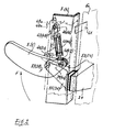
- the recommended track system essentially comprises, as is particularly visible in FIG. 7, a set of front tracks 81G (and 82D) and a set of rear tracks 83G (and 84D) articulated on supports as will be explained now.
- the rear axles have journalled on the supports 78-79 and receive sprockets 85G (and 86D) for toothed belts 87-88 and they carry the track carrier wheels 89G (and 90D) as well as one of the end parts of a support in U 91G (and 92D).
- the other end of the support 91G (and 92D) carries another axis passing through 93G (and 94D) supporting on either side of the support wheels of internal tracks 95G (and 96D) and external 97G (and 98D).
- the external tracks 99G (and 100D) surround the wheels 90-98 with their own grip means (notching for example) and an external folding 101G (and 102D) of the U allows to ensure an internal bearing friction to the tracks which are of course made of a rubbery material.
- the front tracks 103G (and 104D) surround: the track wheels 95-96 and other front wheels 105 G (and 106D) carrying axes 107G (and 108D) journalled forward on U 109G (and 110D) themselves journalled on axes 93-94.
- an internal folding 111G (and 112D) can ensure an internal friction of support for the tracks which are likewise made of a rubbery material.
- the two inclinations will be different which means that the outer frame 12 will itself be in a left inclination, the most unfavorable, which will immediately correct the action of the v roll 28 and pitch 29 rinses controlled by the attitude detector 59.
Landscapes
- Health & Medical Sciences (AREA)
- Life Sciences & Earth Sciences (AREA)
- Animal Behavior & Ethology (AREA)
- General Health & Medical Sciences (AREA)
- Public Health (AREA)
- Veterinary Medicine (AREA)
- Invalid Beds And Related Equipment (AREA)
- Rehabilitation Tools (AREA)
Applications Claiming Priority (2)
| Application Number | Priority Date | Filing Date | Title |
|---|---|---|---|
| FR8517086A FR2590162B1 (fr) | 1985-11-19 | 1985-11-19 | Fauteuil automoteur pour handicape comportant un dispositif de verticalisation automatique |
| FR8517086 | 1985-11-19 |
Publications (1)
| Publication Number | Publication Date |
|---|---|
| EP0226489A1 true EP0226489A1 (de) | 1987-06-24 |
Family
ID=9324957
Family Applications (1)
| Application Number | Title | Priority Date | Filing Date |
|---|---|---|---|
| EP86402478A Withdrawn EP0226489A1 (de) | 1985-11-19 | 1986-11-05 | Selbstfahrender Stuhl für Behinderte mit einer automatischen Aufrichtvorrichtung |
Country Status (2)
| Country | Link |
|---|---|
| EP (1) | EP0226489A1 (de) |
| FR (1) | FR2590162B1 (de) |
Cited By (3)
| Publication number | Priority date | Publication date | Assignee | Title |
|---|---|---|---|---|
| DE3943260A1 (de) * | 1989-12-29 | 1991-07-04 | Kurt Lennartz | Vorrichtung an fahrzeugen zur ueberwindung von fahrhindernissen |
| GB2260896A (en) * | 1991-10-29 | 1993-05-05 | Clive John Hussey | Back support aid |
| EP0839705A2 (de) * | 1996-10-29 | 1998-05-06 | Sunwa Ltd. | Treppensteigendes Fahrzeug zum Transport eines Rollstuhls |
Families Citing this family (3)
| Publication number | Priority date | Publication date | Assignee | Title |
|---|---|---|---|---|
| FR2618066B1 (fr) * | 1987-07-16 | 1989-12-15 | Rolland Bruno | Fauteuil automoteur pour handicape avec dispositif de verticalisation automatique |
| FR2979230B1 (fr) * | 2011-08-24 | 2014-07-11 | Bruno Rolland | Fauteuil automoteur pour personne handicapee |
| EP2722028A1 (de) * | 2012-10-19 | 2014-04-23 | Bruno Rolland | Self-propelled wheelchair for a disabled person |
Citations (6)
| Publication number | Priority date | Publication date | Assignee | Title |
|---|---|---|---|---|
| US3137869A (en) * | 1962-05-18 | 1964-06-23 | Lenard W Johnson | Wheel chair with power lift means |
| CH389827A (de) * | 1962-04-26 | 1965-03-31 | Greub Werner | Treppensteigender Rollstuhl |
| US3394933A (en) * | 1966-04-28 | 1968-07-30 | Suburban Mfg Corp Inc | Invalid lifting and supporting device |
| US4044850A (en) * | 1975-04-14 | 1977-08-30 | Winsor Malcolm C | Wheelchair |
| US4375840A (en) * | 1981-09-23 | 1983-03-08 | Campbell Jack L | Mobile support |
| DE3150193A1 (de) * | 1981-12-18 | 1983-06-30 | Rettungsdienst Stiftung Björn Steiger e.V., 7057 Winnenden | Motorgetriebener rollstuhl fuer koerperbehinderte |
-
1985
- 1985-11-19 FR FR8517086A patent/FR2590162B1/fr not_active Expired
-
1986
- 1986-11-05 EP EP86402478A patent/EP0226489A1/de not_active Withdrawn
Patent Citations (6)
| Publication number | Priority date | Publication date | Assignee | Title |
|---|---|---|---|---|
| CH389827A (de) * | 1962-04-26 | 1965-03-31 | Greub Werner | Treppensteigender Rollstuhl |
| US3137869A (en) * | 1962-05-18 | 1964-06-23 | Lenard W Johnson | Wheel chair with power lift means |
| US3394933A (en) * | 1966-04-28 | 1968-07-30 | Suburban Mfg Corp Inc | Invalid lifting and supporting device |
| US4044850A (en) * | 1975-04-14 | 1977-08-30 | Winsor Malcolm C | Wheelchair |
| US4375840A (en) * | 1981-09-23 | 1983-03-08 | Campbell Jack L | Mobile support |
| DE3150193A1 (de) * | 1981-12-18 | 1983-06-30 | Rettungsdienst Stiftung Björn Steiger e.V., 7057 Winnenden | Motorgetriebener rollstuhl fuer koerperbehinderte |
Cited By (5)
| Publication number | Priority date | Publication date | Assignee | Title |
|---|---|---|---|---|
| DE3943260A1 (de) * | 1989-12-29 | 1991-07-04 | Kurt Lennartz | Vorrichtung an fahrzeugen zur ueberwindung von fahrhindernissen |
| GB2260896A (en) * | 1991-10-29 | 1993-05-05 | Clive John Hussey | Back support aid |
| EP0839705A2 (de) * | 1996-10-29 | 1998-05-06 | Sunwa Ltd. | Treppensteigendes Fahrzeug zum Transport eines Rollstuhls |
| EP0839705A3 (de) * | 1996-10-29 | 1998-07-08 | Sunwa Ltd. | Treppensteigendes Fahrzeug zum Transport eines Rollstuhls |
| US6158536A (en) * | 1996-10-29 | 2000-12-12 | Sunwa Ltd. | Stair-climbing vehicle for wheelchair |
Also Published As
| Publication number | Publication date |
|---|---|
| FR2590162A1 (fr) | 1987-05-22 |
| FR2590162B1 (fr) | 1988-03-11 |
Similar Documents
| Publication | Publication Date | Title |
|---|---|---|
| EP2004124B1 (de) | Stuhl mit mehreren stellungen für körperbehinderte benutzer | |
| EP1864637B1 (de) | Sitz mit Senkrecht-Stellvorrichtung und verstellbarer Rückenlehne | |
| EP2099402B1 (de) | Krankenbett mit seitlicher verschiebungsbewegung | |
| EP0172123A1 (de) | Vorrichtung zum Versetzen eines Kranken aus seinem Bett | |
| CN107296695B (zh) | 一种可变形智能爬楼梯轮椅 | |
| WO2007107651A2 (fr) | Fauteuil roulant adapte aux escaliers | |
| WO2016001451A1 (fr) | Vehicule comprenant un fauteuil articule comprenant un mecanisme de verticalisation | |
| KR102080917B1 (ko) | 전동 휠체어 | |
| JP2000140029A (ja) | 自立用の椅子 | |
| EP0146660B1 (de) | Aufrichtvorrichtung für Rollstuhl und damit versehener Rollstuhl | |
| EP0226489A1 (de) | Selbstfahrender Stuhl für Behinderte mit einer automatischen Aufrichtvorrichtung | |
| EP0720467B1 (de) | Variables geometrisches medizinisches bett | |
| FR2515508A1 (fr) | Fauteuil motorise permettant une assistance au levage | |
| KR100626399B1 (ko) | 높이 조절 기능이 구비된 착탈식 휠체어 | |
| CN213311003U (zh) | 一种轮椅 | |
| EP0880348A1 (de) | Motorischer aufrichtstuhl | |
| EP0495862B1 (de) | Krankenhubeinrichtung | |
| EP0547195B1 (de) | Hilfsvorrichtung zum manipulieren von bettlägerige kranken | |
| EP2722028A1 (de) | Self-propelled wheelchair for a disabled person | |
| FR2915091A1 (fr) | Fauteuil verticalisateur a garde au sol du repose-pied variable | |
| FR2979230A1 (fr) | Fauteuil automoteur pour personne handicapee | |
| FR2513512A1 (fr) | Lit multifonctionnel pour handicape | |
| EP3097898A1 (de) | Medizinischer rollstuhl, der mit einem hilfssystem für patienten zum hinsetzen und aufstehen ausgestattet ist | |
| FR2589341A1 (fr) | Dispositif permettant a une personne handicapee en position assise sur un fauteuil de se degager du siege dudit fauteuil | |
| FI104309B (fi) | Pyörätuoli |
Legal Events
| Date | Code | Title | Description |
|---|---|---|---|
| PUAI | Public reference made under article 153(3) epc to a published international application that has entered the european phase |
Free format text: ORIGINAL CODE: 0009012 |
|
| AK | Designated contracting states |
Kind code of ref document: A1 Designated state(s): AT BE CH DE FR GB IT LI LU NL SE |
|
| STAA | Information on the status of an ep patent application or granted ep patent |
Free format text: STATUS: THE APPLICATION IS DEEMED TO BE WITHDRAWN |
|
| 18D | Application deemed to be withdrawn |
Effective date: 19871229 |