EP0226169A2 - Working platform - Google Patents
Working platform Download PDFInfo
- Publication number
- EP0226169A2 EP0226169A2 EP86117150A EP86117150A EP0226169A2 EP 0226169 A2 EP0226169 A2 EP 0226169A2 EP 86117150 A EP86117150 A EP 86117150A EP 86117150 A EP86117150 A EP 86117150A EP 0226169 A2 EP0226169 A2 EP 0226169A2
- Authority
- EP
- European Patent Office
- Prior art keywords
- working platform
- platform
- segments
- holder
- working
- Prior art date
- Legal status (The legal status is an assumption and is not a legal conclusion. Google has not performed a legal analysis and makes no representation as to the accuracy of the status listed.)
- Withdrawn
Links
Images


Classifications
-
- E—FIXED CONSTRUCTIONS
- E04—BUILDING
- E04G—SCAFFOLDING; FORMS; SHUTTERING; BUILDING IMPLEMENTS OR AIDS, OR THEIR USE; HANDLING BUILDING MATERIALS ON THE SITE; REPAIRING, BREAKING-UP OR OTHER WORK ON EXISTING BUILDINGS
- E04G3/00—Scaffolds essentially supported by building constructions, e.g. adjustable in height
- E04G3/28—Mobile scaffolds; Scaffolds with mobile platforms
-
- E—FIXED CONSTRUCTIONS
- E04—BUILDING
- E04G—SCAFFOLDING; FORMS; SHUTTERING; BUILDING IMPLEMENTS OR AIDS, OR THEIR USE; HANDLING BUILDING MATERIALS ON THE SITE; REPAIRING, BREAKING-UP OR OTHER WORK ON EXISTING BUILDINGS
- E04G3/00—Scaffolds essentially supported by building constructions, e.g. adjustable in height
- E04G3/22—Scaffolds essentially supported by building constructions, e.g. adjustable in height supported by roofs or ceilings
-
- E—FIXED CONSTRUCTIONS
- E04—BUILDING
- E04G—SCAFFOLDING; FORMS; SHUTTERING; BUILDING IMPLEMENTS OR AIDS, OR THEIR USE; HANDLING BUILDING MATERIALS ON THE SITE; REPAIRING, BREAKING-UP OR OTHER WORK ON EXISTING BUILDINGS
- E04G5/00—Component parts or accessories for scaffolds
- E04G5/04—Means for fastening, supporting, or bracing scaffolds on or against building constructions
- E04G5/045—Means for fastening, supporting, or bracing scaffolds on or against building constructions for fastening scaffoldings on profiles, e.g. I or H profiles
-
- E—FIXED CONSTRUCTIONS
- E04—BUILDING
- E04G—SCAFFOLDING; FORMS; SHUTTERING; BUILDING IMPLEMENTS OR AIDS, OR THEIR USE; HANDLING BUILDING MATERIALS ON THE SITE; REPAIRING, BREAKING-UP OR OTHER WORK ON EXISTING BUILDINGS
- E04G3/00—Scaffolds essentially supported by building constructions, e.g. adjustable in height
- E04G3/28—Mobile scaffolds; Scaffolds with mobile platforms
- E04G2003/283—Mobile scaffolds; Scaffolds with mobile platforms mobile horizontally
Definitions
- the subject of this present invention is a working platform intended for doing work at some heights, such as painting, washing and cleaning structures, windows and skylights under the ceilings of rooms, particularly industrial shops.
- work was done with the application of scaffoldings or mechanically lifted platforms, these units being in both the cases placed at the floor level of industrial shops.
- Such designs fulfilled their role only where process equipment and lines had not been installed.
- process equipment and lines had not been installed.
- it was necessary to repair and maintain operating equipment this was too onerous or impossible and, besides, highly expensive due, for example, to the need to stop the operation of a definite shop of a manufacturing works for the period of maintenance or repairs.
- the aim of this present invention has been to avoid the above-mentioned disadvantages by developing a working platform which will enable maintenance and repair work to be done on operating equipment without needing to stop or Limit the normal operation of works production shops.
- the working platform as per this present invention consists of an upper and a lower segments slideably mounted in relation to each other, thereby providing a working surface for carrying out any maintenance or repair.
- the working platform comprises a proper number of hangers used for fixing the platform at a proper height, particularly to the structural components located under the ceilings of industrial shops.
- the longitudinal components of the upper and lower segments are trusses and the transversal components of these same segments are made from beams and barriers, the beams secured to the lower beams of the trusses.
- the upper and lower segments are slid by means of a system of ties wound with cranks onto the drums preferably located on the upper segment and the rolling components shifting in guides, the range of sliding being determined by the position of limiters.
- the upper and lower segments are slid alternately forwards or backwards by the length of the stroke determined by the position of the limiters.
- the working surface of the platform is formed from light landing grates arranged on beams, whereas the hanger comprises a holder, preferably self-clamping under the effect of the action of the force originating from the weight of the working platform and workers and adapted to the shape of the structural components to which the working platform is attached.
- An importent step of preparing the platform for operation is the proper levelling of the upper and lower segments and, consequently, the length of each of the hangers is adjusted, preferably by means of a turnbuckle.
- the length of the beams is adjusted for the proper attachment of the segments.
- the hanger holder comprises a lock preventing the hanger from undesirably disengaging from the structural components, the holder comprising feet or clamps used for attaching the holders to gusset or truss girders depending on the.shape of the same components to which the working platform is attached,
- the working platform is slid directly at a height, whereby the time taken to get the working zone ready is shorter relative conventional designs.
- the simple construction of the working platform guarantees its long life and dependability.
- FIG. 1 shows the working platform in axonometry
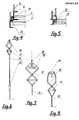
- Fig. 2 shows a diagram of the tie system for shifting the segments of the working platform in the original position
- Fig. 3 shows a diagram of the position of the tie system for shifting the lower segment to the right of the upper segment
- Fig. 4 shows the section marked in Fig. 1 and presenting a rolling component of the working platform in a guide
- Fig. 5 shows the alternative position of the rolling component in a guide.
- Fig. 6 shows a hanger with self-clamping holder
- Fig 7 shows the hanger holder for attaching the working platform to a gusset girder
- Fig. 1 shows the working platform in axonometry
- Fig. 2 shows a diagram of the tie system for shifting the segments of the working platform in the original position
- Fig. 3 shows a diagram of the position of the tie system for shifting the lower segment to the right of the upper segment
- Fig. 4 shows the section marked in Fig. 1 and presenting
- FIG. 8 shows the hanger holder for attaching the working platform to a truss girder
- Fig 9- shows in diagram the shifting phases of the platform
- the working platform consists of upper segment 1 and lower segment 2 which are slideably_mounted relative each other.
- the longitudinal components of upper segment 1 and lower segment 2 are trusses 3 and the transversal components are formed from beams 4 and barriers 5, beams 4 being attached to lower booms 6 of trusses 3.
- Light landing grates 7 are arranged on beams 4 to form working surface 8 of the working platform.
- Upper 1 and lower 2 segments slide relative each other by means of ties 9 wound with cranks 10 onto drums 11 and rolling components 12 moving in guides 13.
- the mutual position of upper 1 and lower 2 segments relative each other is possible within the range determined by the location of limiters 14.
- Each of segments 1 and 2- is attached to the structural components of an industrial shop, for example truss girders or gusset by means of hangers 15 of adjustable length and provided with self-clamping holder 16 with lock 17, the length of the hanger being adjusted with turnbuckle .18.
- the working platform is attached to gusset girders holder 16 is provided with feet 19, whereas in case the working platform is attached to truss girders holder 16 is provided with overlapping clamps 20.
- the lengths of beams 4 and barriers 5 are adjusted.
- the lengths of the longitudinal components of segments 1 and 2 in the form of trusses 3 are a multiple of the structural module of industrial shops.
- Entry to the working platform level can be gained through manhole 21 made in working surface 8 of the platform.
- segments 1 and 2 are placed one above the other.
- a shift of the working platform to the right, for example, as shown in Fig. 3 involves removing hangers 15 from the structural shop components and, then advancing lower segment 2 by the magnitude of the stroke determined by the position of limiters 14 and turning cranks 10 in agreement with the direction marked in Figs 2 and 3.
- Tie system 9 wound onto drum 11 causes lower segment 2 to slide to the right until the position of limiters 14 has been reached, whereafter lower segment 2 should again be secured with hangers 14 to the structural shop components.
- the working platform can be moved longitudinally forward or backward.
Landscapes
- Engineering & Computer Science (AREA)
- Architecture (AREA)
- Mechanical Engineering (AREA)
- Civil Engineering (AREA)
- Structural Engineering (AREA)
- Movable Scaffolding (AREA)
- Cleaning In General (AREA)
- Bridges Or Land Bridges (AREA)
Abstract
Description
- The subject of this present invention is a working platform intended for doing work at some heights, such as painting, washing and cleaning structures, windows and skylights under the ceilings of rooms, particularly industrial shops. Until now, such, work was done with the application of scaffoldings or mechanically lifted platforms, these units being in both the cases placed at the floor level of industrial shops. Such designs fulfilled their role only where process equipment and lines had not been installed. However, wherever it was necessary to repair and maintain operating equipment, this was too onerous or impossible and, besides, highly expensive due, for example, to the need to stop the operation of a definite shop of a manufacturing works for the period of maintenance or repairs.
- The aim of this present invention has been to avoid the above-mentioned disadvantages by developing a working platform which will enable maintenance and repair work to be done on operating equipment without needing to stop or Limit the normal operation of works production shops.
- The working platform as per this present invention consists of an upper and a lower segments slideably mounted in relation to each other, thereby providing a working surface for carrying out any maintenance or repair.
- The working platform comprises a proper number of hangers used for fixing the platform at a proper height, particularly to the structural components located under the ceilings of industrial shops. The longitudinal components of the upper and lower segments are trusses and the transversal components of these same segments are made from beams and barriers, the beams secured to the lower beams of the trusses. The upper and lower segments are slid by means of a system of ties wound with cranks onto the drums preferably located on the upper segment and the rolling components shifting in guides, the range of sliding being determined by the position of limiters. The upper and lower segments are slid alternately forwards or backwards by the length of the stroke determined by the position of the limiters.
- The above enables the platform to be shifted by indexing.
- The working surface of the platform is formed from light landing grates arranged on beams, whereas the hanger comprises a holder, preferably self-clamping under the effect of the action of the force originating from the weight of the working platform and workers and adapted to the shape of the structural components to which the working platform is attached. An importent step of preparing the platform for operation is the proper levelling of the upper and lower segments and, consequently, the length of each of the hangers is adjusted, preferably by means of a turnbuckle.
- Depending on the kind of the structure to which the working platform is attached the length of the beams is adjusted for the proper attachment of the segments.
- Besides, the hanger holder comprises a lock preventing the hanger from undesirably disengaging from the structural components, the holder comprising feet or clamps used for attaching the holders to gusset or truss girders depending on the.shape of the same components to which the working platform is attached, Such a design of the working platform enables maintenance and repairs to be carried out under ceilings, particularly of industrial shops, without any adverse effect on the production activities of-a given works production 'shop. The working platform is slid directly at a height, whereby the time taken to get the working zone ready is shorter relative conventional designs. Besides, the simple construction of the working platform guarantees its long life and dependability.
- This present invention has been presented by an embodiment in a drawing where Fig. 1 shows the working platform in axonometry, Fig. 2 shows a diagram of the tie system for shifting the segments of the working platform in the original position, Fig. 3 shows a diagram of the position of the tie system for shifting the lower segment to the right of the upper segment, Fig. 4 shows the section marked in Fig. 1 and presenting a rolling component of the working platform in a guide, Fig. 5 shows the alternative position of the rolling component in a guide. Fig. 6 shows a hanger with self-clamping holder, Fig 7 shows the hanger holder for attaching the working platform to a gusset girder, Fig. 8 shows the hanger holder for attaching the working platform to a truss girder, Fig 9-shows in diagram the shifting phases of the platform The working platform consists of
upper segment 1 andlower segment 2 which are slideably_mounted relative each other. The longitudinal components ofupper segment 1 andlower segment 2 aretrusses 3 and the transversal components are formed frombeams 4 andbarriers 5,beams 4 being attached tolower booms 6 oftrusses 3.Light landing grates 7 are arranged onbeams 4 to form working surface 8 of the working platform. - Upper 1 and lower 2 segments slide relative each other by means of
ties 9 wound withcranks 10 ontodrums 11 androlling components 12 moving inguides 13. The mutual position of upper 1 and lower 2 segments relative each other is possible within the range determined by the location of limiters 14. Each ofsegments 1 and 2-is attached to the structural components of an industrial shop, for example truss girders or gusset by means ofhangers 15 of adjustable length and provided with self-clamping holder 16 withlock 17, the length of the hanger being adjusted with turnbuckle .18. - In case the working platform is attached to
gusset girders holder 16 is provided withfeet 19, whereas in case the working platform is attached totruss girders holder 16 is provided with overlappingclamps 20. Depending on the kind of the construction of industrial shops which impose definite spans for the attachment of the working platform, the lengths ofbeams 4 andbarriers 5 are adjusted. On the other hand, the lengths of the longitudinal components ofsegments trusses 3 are a multiple of the structural module of industrial shops. - Entry to the working platform level can be gained through
manhole 21 made in working surface 8 of the platform. - In their original position,
segments hangers 15 from the structural shop components and, then advancinglower segment 2 by the magnitude of the stroke determined by the position of limiters 14 and turningcranks 10 in agreement with the direction marked in Figs 2 and 3. -
Tie system 9 wound ontodrum 11 causeslower segment 2 to slide to the right until the position of limiters 14 has been reached, whereafterlower segment 2 should again be secured with hangers 14 to the structural shop components. By alternately sliding upper 1 and lower 2 segments, the working platform can be moved longitudinally forward or backward.
Claims (4)
- ing platform is attached, the length of hanger 15 being preferably adjusted with turnbuckle 18.
- 6. A working platform as per Claim 2, characterised in that the length of beams 4 and barriers 5 is adjustable.
- 7. A working platform as per Claim 5, characterised in that holder 16 includes lock 17.
- 8. A working platform as per Claim 5 or 7, characterised in that holder 16 includes feet 19 or clamps 20 depending on the shape of the structural components to which the working platform is attached.
Applications Claiming Priority (2)
| Application Number | Priority Date | Filing Date | Title |
|---|---|---|---|
| PL256760 | 1985-12-11 | ||
| PL1985256760A PL143813B2 (en) | 1985-12-11 | 1985-12-11 | Working platform |
Publications (2)
| Publication Number | Publication Date |
|---|---|
| EP0226169A2 true EP0226169A2 (en) | 1987-06-24 |
| EP0226169A3 EP0226169A3 (en) | 1988-09-07 |
Family
ID=20029447
Family Applications (1)
| Application Number | Title | Priority Date | Filing Date |
|---|---|---|---|
| EP86117150A Withdrawn EP0226169A3 (en) | 1985-12-11 | 1986-12-09 | Working platform |
Country Status (2)
| Country | Link |
|---|---|
| EP (1) | EP0226169A3 (en) |
| PL (1) | PL143813B2 (en) |
Cited By (9)
| Publication number | Priority date | Publication date | Assignee | Title |
|---|---|---|---|---|
| WO1994000656A1 (en) * | 1992-06-26 | 1994-01-06 | John Clement Preston | A building site rubbish collection facility |
| FR2694323A1 (en) * | 1992-07-29 | 1994-02-04 | France Etat Armement | Scissor type tackle for suspending loads under platforms - comprises self-closing scissors type device opening at top with bent arms which close round supporting 'T' or 'I' sections with two upper arms connected roughly at midpoints by pin |
| FR2763619A1 (en) * | 1997-05-20 | 1998-11-27 | Frederic Buchmann | Support structure for workers cleaning glass ceilings |
| GB2409851A (en) * | 2004-01-12 | 2005-07-13 | Aus Struct Services Pty Ltd | Work Platform |
| FR2865753A1 (en) * | 2004-01-31 | 2005-08-05 | Stacco | Platform for temporary or permanent construction e.g. theatre, has openwork structure defining support surface and formed by networks of cables, and suspension cable or chain passes through mesh of structure |
| AU2004200088B2 (en) * | 2002-03-21 | 2009-09-10 | Aus Struct Services Pty Ltd | Work platform |
| CN107119897A (en) * | 2017-06-29 | 2017-09-01 | 中国五冶集团有限公司 | Slding form operation support platform |
| CN109025234A (en) * | 2018-07-28 | 2018-12-18 | 北京建工集团有限责任公司 | A kind of building high-altitude vacantly construct with can level, vertically the track crane ship that walk |
| CN109057309A (en) * | 2018-09-13 | 2018-12-21 | 中信国安建工集团有限公司 | A kind of suspended operating platform and its mounting and dismounting method |
Citations (6)
| Publication number | Priority date | Publication date | Assignee | Title |
|---|---|---|---|---|
| GB191006943A (en) * | 1910-03-19 | 1910-11-17 | Hadrian Bayley | Improvements in Fire-escapes. |
| GB191109147A (en) * | 1911-04-12 | 1912-04-11 | Percy Edgar Beaumont | Improvements in Slung Cradles or Staging for Builders & the like. |
| US3096064A (en) * | 1961-03-23 | 1963-07-02 | Henderson G Leonard | Suspension structure for demountable scaffolds |
| CH493719A (en) * | 1969-05-08 | 1970-07-15 | Charles Coombs William | Hanging scaffolding |
| US3945462A (en) * | 1975-06-18 | 1976-03-23 | Griswold James D | Hanger brackets |
| EP0094297A1 (en) * | 1982-05-11 | 1983-11-16 | Daniel Gautier | Hanging scaffold movable with respect to a structure, and method of moving such a scaffold |
-
1985
- 1985-12-11 PL PL1985256760A patent/PL143813B2/en unknown
-
1986
- 1986-12-09 EP EP86117150A patent/EP0226169A3/en not_active Withdrawn
Patent Citations (6)
| Publication number | Priority date | Publication date | Assignee | Title |
|---|---|---|---|---|
| GB191006943A (en) * | 1910-03-19 | 1910-11-17 | Hadrian Bayley | Improvements in Fire-escapes. |
| GB191109147A (en) * | 1911-04-12 | 1912-04-11 | Percy Edgar Beaumont | Improvements in Slung Cradles or Staging for Builders & the like. |
| US3096064A (en) * | 1961-03-23 | 1963-07-02 | Henderson G Leonard | Suspension structure for demountable scaffolds |
| CH493719A (en) * | 1969-05-08 | 1970-07-15 | Charles Coombs William | Hanging scaffolding |
| US3945462A (en) * | 1975-06-18 | 1976-03-23 | Griswold James D | Hanger brackets |
| EP0094297A1 (en) * | 1982-05-11 | 1983-11-16 | Daniel Gautier | Hanging scaffold movable with respect to a structure, and method of moving such a scaffold |
Cited By (10)
| Publication number | Priority date | Publication date | Assignee | Title |
|---|---|---|---|---|
| WO1994000656A1 (en) * | 1992-06-26 | 1994-01-06 | John Clement Preston | A building site rubbish collection facility |
| FR2694323A1 (en) * | 1992-07-29 | 1994-02-04 | France Etat Armement | Scissor type tackle for suspending loads under platforms - comprises self-closing scissors type device opening at top with bent arms which close round supporting 'T' or 'I' sections with two upper arms connected roughly at midpoints by pin |
| FR2763619A1 (en) * | 1997-05-20 | 1998-11-27 | Frederic Buchmann | Support structure for workers cleaning glass ceilings |
| AU2004200088B2 (en) * | 2002-03-21 | 2009-09-10 | Aus Struct Services Pty Ltd | Work platform |
| GB2409851A (en) * | 2004-01-12 | 2005-07-13 | Aus Struct Services Pty Ltd | Work Platform |
| GB2409851B (en) * | 2004-01-12 | 2006-06-07 | Aus Struct Services Pty Ltd | Work platform |
| FR2865753A1 (en) * | 2004-01-31 | 2005-08-05 | Stacco | Platform for temporary or permanent construction e.g. theatre, has openwork structure defining support surface and formed by networks of cables, and suspension cable or chain passes through mesh of structure |
| CN107119897A (en) * | 2017-06-29 | 2017-09-01 | 中国五冶集团有限公司 | Slding form operation support platform |
| CN109025234A (en) * | 2018-07-28 | 2018-12-18 | 北京建工集团有限责任公司 | A kind of building high-altitude vacantly construct with can level, vertically the track crane ship that walk |
| CN109057309A (en) * | 2018-09-13 | 2018-12-21 | 中信国安建工集团有限公司 | A kind of suspended operating platform and its mounting and dismounting method |
Also Published As
| Publication number | Publication date |
|---|---|
| PL256760A2 (en) | 1986-11-04 |
| PL143813B2 (en) | 1988-03-31 |
| EP0226169A3 (en) | 1988-09-07 |
Similar Documents
| Publication | Publication Date | Title |
|---|---|---|
| US5522472A (en) | Fall protection system for bridge construction | |
| EP0226169A2 (en) | Working platform | |
| US4854419A (en) | Particulate containment control method and platform device | |
| US3524520A (en) | Traveling scaffold | |
| ATE81878T1 (en) | SERVICE SYSTEM. | |
| KR100401251B1 (en) | mobile and fixative bridge maintaining system | |
| KR200392341Y1 (en) | Fixing Device for Aerial Scaffolding | |
| JPH0860620A (en) | Installation method of main girder | |
| GB1589515A (en) | Means for renovating and refurbishing of overhead structures | |
| US4319374A (en) | Method of constructing a stayed girder bridge | |
| JPH07103679B2 (en) | Suspension scaffold assembly method and scaffold material used for it | |
| KR100377529B1 (en) | Working platform for bridge construction | |
| EP0001342A1 (en) | Improvements in girder fittings | |
| JPH0372165A (en) | Lifting fixture | |
| RU2298423C2 (en) | Method for protecting of worker during repair and construction, restoration and prophylactic works on vertical surface of buildings and constructions, and protective apparatus for performing the same | |
| JPH08184178A (en) | Connection space cover for suspended scaffold and connection space covering structure | |
| SU663806A1 (en) | Method of erecting tubular building scaffold | |
| SU881265A1 (en) | Construction cradle | |
| JP2621748B2 (en) | All-weather temporary shed | |
| SU75489A1 (en) | Mobile scaffolding for the repair and inspection of bridges with beams | |
| SU499204A1 (en) | Lifting beam | |
| SU727793A1 (en) | Suspended scaffold | |
| SU670523A1 (en) | Crane trestle | |
| SU614012A1 (en) | Crane unit | |
| JPH0372166A (en) | Lifting fixture |
Legal Events
| Date | Code | Title | Description |
|---|---|---|---|
| PUAI | Public reference made under article 153(3) epc to a published international application that has entered the european phase |
Free format text: ORIGINAL CODE: 0009012 |
|
| AK | Designated contracting states |
Kind code of ref document: A2 Designated state(s): AT BE CH DE ES FR GB IT LI NL SE |
|
| PUAL | Search report despatched |
Free format text: ORIGINAL CODE: 0009013 |
|
| AK | Designated contracting states |
Kind code of ref document: A3 Designated state(s): AT BE CH DE ES FR GB IT LI NL SE |
|
| 17P | Request for examination filed |
Effective date: 19890126 |
|
| 17Q | First examination report despatched |
Effective date: 19900207 |
|
| STAA | Information on the status of an ep patent application or granted ep patent |
Free format text: STATUS: THE APPLICATION IS DEEMED TO BE WITHDRAWN |
|
| 18D | Application deemed to be withdrawn |
Effective date: 19900619 |
|
| RIN1 | Information on inventor provided before grant (corrected) |
Inventor name: NOWAK, MACIEJ Inventor name: GAWRON, FRYDERYK |