EP0225901B1 - Rohrleitung, insbesondere für den transport von fluiden, deren durchlässigkeit gegenüber den transportierten fluiden eingeschränkt ist - Google Patents
Rohrleitung, insbesondere für den transport von fluiden, deren durchlässigkeit gegenüber den transportierten fluiden eingeschränkt ist Download PDFInfo
- Publication number
- EP0225901B1 EP0225901B1 EP86903424A EP86903424A EP0225901B1 EP 0225901 B1 EP0225901 B1 EP 0225901B1 EP 86903424 A EP86903424 A EP 86903424A EP 86903424 A EP86903424 A EP 86903424A EP 0225901 B1 EP0225901 B1 EP 0225901B1
- Authority
- EP
- European Patent Office
- Prior art keywords
- pipe
- layer
- sheath
- accordance
- metal strip
- Prior art date
- Legal status (The legal status is an assumption and is not a legal conclusion. Google has not performed a legal analysis and makes no representation as to the accuracy of the status listed.)
- Expired
Links
Images

Classifications
-
- F—MECHANICAL ENGINEERING; LIGHTING; HEATING; WEAPONS; BLASTING
- F16—ENGINEERING ELEMENTS AND UNITS; GENERAL MEASURES FOR PRODUCING AND MAINTAINING EFFECTIVE FUNCTIONING OF MACHINES OR INSTALLATIONS; THERMAL INSULATION IN GENERAL
- F16L—PIPES; JOINTS OR FITTINGS FOR PIPES; SUPPORTS FOR PIPES, CABLES OR PROTECTIVE TUBING; MEANS FOR THERMAL INSULATION IN GENERAL
- F16L11/00—Hoses, i.e. flexible pipes
- F16L11/14—Hoses, i.e. flexible pipes made of rigid material, e.g. metal or hard plastics
- F16L11/16—Hoses, i.e. flexible pipes made of rigid material, e.g. metal or hard plastics wound from profiled strips or bands
-
- F—MECHANICAL ENGINEERING; LIGHTING; HEATING; WEAPONS; BLASTING
- F16—ENGINEERING ELEMENTS AND UNITS; GENERAL MEASURES FOR PRODUCING AND MAINTAINING EFFECTIVE FUNCTIONING OF MACHINES OR INSTALLATIONS; THERMAL INSULATION IN GENERAL
- F16L—PIPES; JOINTS OR FITTINGS FOR PIPES; SUPPORTS FOR PIPES, CABLES OR PROTECTIVE TUBING; MEANS FOR THERMAL INSULATION IN GENERAL
- F16L11/00—Hoses, i.e. flexible pipes
- F16L11/04—Hoses, i.e. flexible pipes made of rubber or flexible plastics
- F16L11/08—Hoses, i.e. flexible pipes made of rubber or flexible plastics with reinforcements embedded in the wall
- F16L11/081—Hoses, i.e. flexible pipes made of rubber or flexible plastics with reinforcements embedded in the wall comprising one or more layers of a helically wound cord or wire
- F16L11/083—Hoses, i.e. flexible pipes made of rubber or flexible plastics with reinforcements embedded in the wall comprising one or more layers of a helically wound cord or wire three or more layers
-
- F—MECHANICAL ENGINEERING; LIGHTING; HEATING; WEAPONS; BLASTING
- F16—ENGINEERING ELEMENTS AND UNITS; GENERAL MEASURES FOR PRODUCING AND MAINTAINING EFFECTIVE FUNCTIONING OF MACHINES OR INSTALLATIONS; THERMAL INSULATION IN GENERAL
- F16L—PIPES; JOINTS OR FITTINGS FOR PIPES; SUPPORTS FOR PIPES, CABLES OR PROTECTIVE TUBING; MEANS FOR THERMAL INSULATION IN GENERAL
- F16L11/00—Hoses, i.e. flexible pipes
- F16L11/04—Hoses, i.e. flexible pipes made of rubber or flexible plastics
- F16L11/10—Hoses, i.e. flexible pipes made of rubber or flexible plastics with reinforcements not embedded in the wall
-
- F—MECHANICAL ENGINEERING; LIGHTING; HEATING; WEAPONS; BLASTING
- F16—ENGINEERING ELEMENTS AND UNITS; GENERAL MEASURES FOR PRODUCING AND MAINTAINING EFFECTIVE FUNCTIONING OF MACHINES OR INSTALLATIONS; THERMAL INSULATION IN GENERAL
- F16C—SHAFTS; FLEXIBLE SHAFTS; ELEMENTS OR CRANKSHAFT MECHANISMS; ROTARY BODIES OTHER THAN GEARING ELEMENTS; BEARINGS
- F16C2326/00—Articles relating to transporting
- F16C2326/01—Parts of vehicles in general
- F16C2326/06—Drive shafts
-
- F—MECHANICAL ENGINEERING; LIGHTING; HEATING; WEAPONS; BLASTING
- F16—ENGINEERING ELEMENTS AND UNITS; GENERAL MEASURES FOR PRODUCING AND MAINTAINING EFFECTIVE FUNCTIONING OF MACHINES OR INSTALLATIONS; THERMAL INSULATION IN GENERAL
- F16L—PIPES; JOINTS OR FITTINGS FOR PIPES; SUPPORTS FOR PIPES, CABLES OR PROTECTIVE TUBING; MEANS FOR THERMAL INSULATION IN GENERAL
- F16L11/00—Hoses, i.e. flexible pipes
- F16L11/04—Hoses, i.e. flexible pipes made of rubber or flexible plastics
- F16L2011/047—Hoses, i.e. flexible pipes made of rubber or flexible plastics with a diffusion barrier layer
Definitions
- the present invention relates to a pipe which can be used in particular for transporting fluids and making it possible to limit the permeability to transported fluids, for example to corrosive fluids.
- the invention applies in particular to the field of transporting liquid or gaseous fluids, in particular hydrocarbons, in pipes capable of being used under high pressure and at high temperatures for long periods of time.
- flexible tubes or flexible, is meant here pipes having sufficient flexibility to accept (without deterioration) a radius of curvature R of value less than or equal to axd, d being the diameter of the tube measured with the same unit R and has a numerical coefficient whose value does not exceed a few units, 4 to 5 for example.
- the pressure prevailing between the two sealing sheaths may become greater than the external pressure applied to the hose and cause the external sheath to burst.
- European patent application EP-A-0 111 169 relates to a gas-tight multilayer tube. It notably includes a metal casing secured to the outer periphery of a plastic sheath as well as the inner periphery of an outer tube.
- the integral assembly is wound in an edge-to-edge spiral, either hot so as to form a seal with the plastic sheath made soft, or by means of a cold or hot-setting adhesive.
- This edge-to-edge winding technique of layers integral with each other can only be applied to rigid tubes and not to hoses which would then lose all their flexibility.
- Patent FR-A-2 467 347 describes a flexible tube which is resistant in particular to radial loads, in particular to both internal and external forces.
- This tube consists of a core tube made of elastic material, for sealing against transported fluids, which is covered with a profiled strip having a Z-shaped profile intended to withstand the pressure forces directed either inward or towards the outside of the tube.
- This profiled strip which serves as pressure armor and which is tensile strength does not make it possible, in particular due to its rigidity, to significantly limit the permeability of the tube to gases.
- the present invention makes it possible to limit the permeability through flexible sheaths without modifying the internal geometry of the tube and without reducing the flexibility of the pipe. It relates to a pipe as defined in claim 1.
- One of the essential advantages of the covering thus ensured according to the invention is the contact of the metal layers under the effect of the pressure of the fluids on the internal sheath, which reinforces the sealing of the hose while maintaining its flexibility intact, since the turns can play on each other.
- the metallic layer may comprise a layer of metallic tape glued to said inner sheath over a part of the width of this layer in contact with said inner sheath, the turns of the metallic tape being able to play freely on each other, which gives a large freedom of movement in turns during winding tests or unwinding of the hose.
- the metal layer may also comprise a layer of metallic tape bonded to an external envelope over part of the width of this layer in contact with said external envelope, the turns of the metallic ribbon possibly play freely on each other.
- Bonding as described may make it possible to avoid modifications in the winding pitch which may result from deformations of the pipe during its handling for storage or / and in service.
- Bonding can, moreover, be carried out continuously or discontinuously, but preferably better results have been obtained when the bonding was continuous on a portion of the tape in contact with one or the other of the flexible sheaths.
- the tape can be glued at the edge in contact with said inner sheath or with the outer envelope, which can make it possible to avoid the relative movements of this edge in contact with the sheath or envelope and reduce the risk of nicking the sheath or the envelope by this edge in contact with the interior or exterior fluid.
- the metal layer according to the invention can be glued with an adhesive which can be hardened cold or hot or hot-melt depending on the case or the type of material.
- an adhesion primer can be deposited on the sheath and / or the tape.
- the pipe can comprise at least two superposed layers of metallic tape, the layer of tape in contact with the inner sheath being glued to it over part of the width of the metallic tape and the layer in contact with the outer sheath being bonded thereto over part of the width of the metal strip.
- the objective of the present invention applied to rigid pipes is achieved when winding between the flexible inner sheath and the outer sheath comprising the winding of fibers pre-impregnated with a thermosetting resin at least one layer of flat metallic tape which is bonded to the inner sheath over the major part at least of the width of the ribbon.
- This ribbon is wound in a spiral with a winding angle a greater than 50 ° and less than 90 ° relative to the axis of the pipe, the turns of this ribbon having overlapping zones so as to ensure total recovery of said inner sheath, the overlapping zones of the turns of the ribbon on the one hand, and the zones included between said overlapping zones on the other hand, each having a width at least equal to the amplitude of the deformation imposed on said sheaths by the maximum traction or bending of the pipe or during decompression.
- the overlapping areas are not pasted. However, if we prefer to stick them to improve the seal, we will preferably choose a flexible neoprene type adhesive capable of accepting the imposed deformation.
- Bonding as described can make it possible to obtain a pipe of constant cross-section almost gas tight and to avoid modifications of the winding pitch which may result from deformations of the pipe during its handling for storage or / and in service.
- amorphous metal or of alloys of amorphous metals As well for rigid pipes as flexible pipes, it is possible, preferably, to use ribbons of amorphous metal or of alloys of amorphous metals, as described in the French invention patents FR-A-2 368 324 and FR-A-2 381 581, due to their mechanical properties superior to those of the corresponding metals or alloys of crystalline metals, in particular their characteristics of resistance and hardness up to 3700 MPa (370 kg / mm 2 ) and 1100 MPa ( 1100 kg / mm 2 ) respectively and their high yield strength.
- These amorphous metals are usually used for their isotropic mechanical strengths and other isotropic physical properties such as the ability to magnetize.
- the fluids capable of being transported are corrosive, it is possible to use in a preferred manner, especially when the fluids contain hydrogen sulphide, corrosion-resistant metals such as alloys having a composition which comprises in particular chromium and / or nickel and / or cobalt and / or molybdenum.
- the width of the ribbons will preferably be at least equal to 1 cm and its thickness may vary from 1/100 mm to a few tenths of a millimeter and preferably from 5/100 mm to 5/10 mm.
- thermoplastics or elastomers that can be extruded can be used with wall thicknesses adapted according to each load case.
- Polyamides, polyolefins or fluoropolymers (P.V.D.F.) and synthetic or natural elastomers can, for example, be used as a thermoplastic.
- the pipe comprises several sheaths of thermoplastic material or elastomer, such as an outer sheath and an inner sheath, the material of one may be different from the latter of the other.
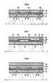
- FIGS. 1 to 5 where XY represents the longitudinal axis of the hose 10, an inner tube or sheath of thermoplastic or elastomer 1 was extruded and a metallic strip 3 was wound according to the invention with a sufficient tension for the 'apply against the inner sheath 1.
- the ribbon has been wound in a helix at an angle a greater than 50 ° and less than 90 ° relative to the axis of the pipe, and with overlapping zones (30, Fig. 1 ; 15, 16 and 17, Fig. 4) of width at least equal to the amplitude of the deformation (elongation or shortening) imposed on storage and / or in service on the outer sheath 10 which may include an outer casing 2 and a metal layer 3.
- This external sheath 10 has been extruded over the metal layer according to the invention and is applied to its external part.
- this strip 3 can optionally be glued over a part of the width which is in contact 4, or even on the edge in contact 5 with said inner sheath 1 of the hose.
- the tape can be glued to a part in contact 6, or even to the edge in contact 7 with the outer casing 2 of the hose.
- FIG. 4 represents another embodiment of the hose according to the invention where a first layer of tape 3 has been wound on the inner sheath 1, the turns 11 and 12 of which do not overlap and where the second layer 3a with the turns 13 and 14 cover the previous ones by resting on the facing edges 15, 16 and 17 of the turns 11 and 12 of the layer 3.
- the turns of layer 3 are bonded at 5 to the inner sheath 1 and the turns of layer 3a are bonded at 7 to the outer casing 2.
- an inner sheath 1 of thickness 4 mm made of Rilsan 11 (registered trademark) was extruded over a strip 21 of outside diameter 100 mm in stainless steel.
- a thin film of hot-melt adhesive compatible with Rilsan 11, 3 mm wide, is deposited on the inner sheath at a spiral winding angle equal to that which was adopted for winding the tape, that is approximately 84 °, corresponding to a pitch of 24 mm.
- the ribbon 3 of amorphous metal alloy preheated to a temperature substantially higher than the glue softening temperature, is wound in a spiral according to a known technique, under a winding tension of 200 Newton.
- the width of the overlapping zones of the adjacent turns represents approximately 20% of the width of these turns, that is 6 mm in the example considered and the ribbon is deposited in such a way that only the edge 5 of the ribbon is glued to the inner sheath 1 .
- a flexible outer casing 2 of medium density polyethylene 2 mm thick was then extruded according to a known technique, which covers the metal layer 3 according to the invention.
- a layer of flat metallic tape 33 is wound and glued 35 with sufficient tension around a soft, flexible inner sheath 31, made of thermoplastic material or elastomer which, therefore, is supported by the inner face of the ribbon.
- the glue was deposited on the largest surface in contact between the sheath 31 and the layer 33.
- the ribbon consists of a winding of turns 34 with an angle ⁇ greater than 50 ° and less than 90 ° relative to the axis XY.
- the turns 34 of this ribbon 33 have overlapping zones 36 so as to accept possible deformations during decompression of the pipe and to ensure total recovery of the inner sheath 31.
- the overlapping zones 36 of the turns 34 of the tape and the areas between the overlapping areas each have a width at least equal to the amplitude of the deformation (decompression, elongation or shortening) imposed on the sheaths 32 of the pipe.
- the pipe comprising the sheath 31 and the ribbon 33 is surrounded by an external sheath 32 of composite material wound at an angle of less than 90 ° relative to the axis of the pipe, according to a known technique. by those skilled in the art.
- the composite materials used can be, for example, glass, carbon or Kevlar (registered trademark) fibers impregnated with resin, for example epoxy, or composites based on steel strip.
- Figure 7 illustrates another embodiment of rigid pipe where one has wound on the inner sheath upper 31 a first layer of tape 33 whose turns 41 and 42 do not overlap and a second layer 33a whose turns 43 and 44 cover the previous ones by resting on the facing edges 45, 44, 47 of the turns 41 and 42 of layer 33.
- the turns of layer 33 are glued at 35 over at least the major part of the width in contact with the inner sheath and preferably over the entire width of the turns.
- FIG. 8 another embodiment of a rigid high performance pipe is shown where the inner sheath 31 is glued 35 and thus supported by the metal layer 33 made up of turns 34.
- thermoplastic or elastomer sheath 31 b has been extruded which is applied and adhered against this layer 33 which, therefore, is housed in this soft sheath comprising the sheaths 31 and 31 b.
- the sheath 31 b thus stiffened and substantially gas tight is then surrounded by at least one outer sheath made of composite material 32 as described above.
- the rigid pipe in its preferred embodiment (Fig. 8), to withstand high pressures of the order of 300 bars and at high temperatures, has an inner sheath 2 mm thick in "Rilsan 1 1" (registered trademark) and 15 cm in diameter.
- a thin film of hot-melt adhesive compatible with the Rilsan 11 with a width of 20 cm is deposited on the inner sheath, at a spiral winding angle equal to that which has been adapted for winding the tape, ie around 84 °.
- the ribbon 33 of amorphous metal alloy, preheated to a temperature substantially higher than the glue softening temperature, is wound in a spiral according to a known technique, under a winding tension of 200 Newton.
- the width of the overlapping zones of the adjacent turns represents approximately 20% of the width of these turns, that is 6 mm in the example considered and the ribbon is deposited in such a way that most of the width of the turns of the ribbon 33 is glued to the inner sheath 31.
- a plastic sheath 31 b of Rilsan 11 with a thickness of 1 mm is extruded according to a known technique, which will level the layer 33 and finally above this sheath 31 b, at least a layer of composite fibers as described, according to winding angles known to those skilled in the art and compatible with the tension and compression forces which the pipeline must resist.
- the pipes according to the invention described above can in particular serve as means of transporting corrosive hydrocarbon fluids under pressure and more or less high temperature. These pipes can be used for drilling and hydrocarbon production operations which require high dynamic constraints, the metal layer 3, 33 possibly being used to convey electrical information from the subsoil to the surface and from the surface to the sub -ground.
- Rigid pipes can be used in particular as risers in drilling and in the production of hydrocarbons.
Landscapes
- Engineering & Computer Science (AREA)
- General Engineering & Computer Science (AREA)
- Mechanical Engineering (AREA)
- Rigid Pipes And Flexible Pipes (AREA)
- Laminated Bodies (AREA)
Claims (16)
Applications Claiming Priority (4)
| Application Number | Priority Date | Filing Date | Title |
|---|---|---|---|
| FR8508938A FR2583133B1 (fr) | 1985-06-11 | 1985-06-11 | Canalisation utilisable notamment pour le transport de fluides et permettant de limiter la permeabilite aux fluides transportes |
| FR8508938 | 1985-06-11 | ||
| FR8514019 | 1985-09-20 | ||
| FR8514019A FR2587783B2 (fr) | 1985-09-20 | 1985-09-20 | Canalisation utilisable notamment pour le transport de fluides et permettant de limiter la permeabilite aux fluides transportes |
Publications (2)
| Publication Number | Publication Date |
|---|---|
| EP0225901A1 EP0225901A1 (de) | 1987-06-24 |
| EP0225901B1 true EP0225901B1 (de) | 1989-12-20 |
Family
ID=26224560
Family Applications (1)
| Application Number | Title | Priority Date | Filing Date |
|---|---|---|---|
| EP86903424A Expired EP0225901B1 (de) | 1985-06-11 | 1986-06-06 | Rohrleitung, insbesondere für den transport von fluiden, deren durchlässigkeit gegenüber den transportierten fluiden eingeschränkt ist |
Country Status (5)
| Country | Link |
|---|---|
| US (1) | US4903735A (de) |
| EP (1) | EP0225901B1 (de) |
| JP (1) | JPH0659716B2 (de) |
| BR (1) | BR8606725A (de) |
| WO (1) | WO1986007432A1 (de) |
Families Citing this family (60)
| Publication number | Priority date | Publication date | Assignee | Title |
|---|---|---|---|---|
| US5275209A (en) * | 1988-05-09 | 1994-01-04 | Institut Francais Du Petrole | Hose including an aluminum alloy |
| US5271977A (en) * | 1989-02-10 | 1993-12-21 | Bridgestone Corporation | Low permeable rubber hose |
| FR2645792B1 (fr) * | 1989-04-13 | 1991-10-25 | Aerospatiale | Tube en materiau composite a revetement thermoplastique fibre et procede de fabrication d'un tel tube |
| US5645109A (en) * | 1990-06-29 | 1997-07-08 | Coflexip | Flexible tubular pipe comprising an interlocked armoring web and process for producing it |
| NL9001653A (nl) * | 1990-07-19 | 1992-02-17 | Wavin Bv | Samengestelde buis met een of meer lagen rond een binnenbuis gewikkeld bandvormig materiaal. |
| US5261462A (en) * | 1991-03-14 | 1993-11-16 | Donald H. Wolfe | Flexible tubular structure |
| US5259418A (en) * | 1991-03-18 | 1993-11-09 | Hamrick James C | Heat reshapeable regid conduit |
| FR2674933B1 (fr) * | 1991-04-05 | 1993-06-11 | Caoutchouc Manuf Plastique | Procede de realisation en continu d'une structure tubulaire souple comportant un feuil monocouche d'epaisseur micrometrique incorpore et structures tubulaires souples realisees selon ce procede. |
| FR2674934B1 (fr) * | 1991-04-05 | 1993-08-20 | Caoutchouc Manuf Plastique | Procede de realisation en continu d'une structure tubulaire souple comportant un feuil multicouche d'epaisseur micrometrique incorpore et structures tubulaires souples realisees selon ce procede. |
| US5434209A (en) * | 1991-06-27 | 1995-07-18 | Basf Aktiengesellschaft | Flameproofed thermoplastic polyamide molding materials |
| US5398729A (en) * | 1992-08-25 | 1995-03-21 | Cooper Tire & Rubber Company | Low permeation fuel hose |
| US5340508A (en) * | 1992-11-23 | 1994-08-23 | Clean-Flo Laboratories, Inc. | Aeration system and method |
| US5837083A (en) * | 1993-08-12 | 1998-11-17 | Booth; John Peter | Method of forming a rigid tubular body |
| US5645110A (en) * | 1994-12-01 | 1997-07-08 | Nobileau; Philippe | Flexible high pressure pipe |
| US5685576A (en) * | 1995-06-06 | 1997-11-11 | Wolfe; Donald H. | Pipe coupling |
| US5765285A (en) * | 1995-08-09 | 1998-06-16 | The B.F. Goodrich Company | Method of bending a rigid thermoplastic pipe |
| DE19635487A1 (de) * | 1995-09-05 | 1997-03-13 | Phoenix Ag | Sicherheitsschlauch |
| US7498509B2 (en) * | 1995-09-28 | 2009-03-03 | Fiberspar Corporation | Composite coiled tubing end connector |
| US5921285A (en) * | 1995-09-28 | 1999-07-13 | Fiberspar Spoolable Products, Inc. | Composite spoolable tube |
| US8678042B2 (en) | 1995-09-28 | 2014-03-25 | Fiberspar Corporation | Composite spoolable tube |
| FR2743858B1 (fr) * | 1996-01-22 | 1998-02-13 | Coflexip | Utilisation d'une conduite flexible ensouillee |
| US5927224A (en) * | 1996-06-21 | 1999-07-27 | Fmc Corporation | Dual function mooring lines for storage vessel |
| FR2756358B1 (fr) * | 1996-11-22 | 1999-01-29 | Inst Francais Du Petrole | Gaine a permeabilite limitee et application aux conduites sous pression |
| US5893681A (en) * | 1997-01-06 | 1999-04-13 | Senior Engineering Investments Ag | Flexible pipe having a flexible wrap applied thereto and method for attaching the wrap |
| DE19837497A1 (de) | 1998-08-13 | 2000-02-24 | Trinova Aeroquip Gmbh | Flexibler strangförmiger Hohlkörper |
| DE19837498A1 (de) | 1998-08-13 | 2000-02-24 | Trinova Aeroquip Gmbh | Flexibler strangförmiger Hohlkörper |
| ES2178467T3 (es) * | 1998-08-13 | 2002-12-16 | Trinova Aeroquip Gmbh | Cuerpo hueco en forma de barra flexible. |
| FR2784445B1 (fr) | 1998-10-12 | 2000-11-17 | Coflexip | Conduite flexible a frette de forte inertie |
| US20040226623A1 (en) * | 1999-10-12 | 2004-11-18 | Oem/Miller, A Division Of Holm Industries | Dual wall co-extruded corrugated tubing |
| AU780180B2 (en) * | 1999-11-05 | 2005-03-03 | Prime Flexible Products, Inc. | Flexible pipe and method of manufacturing same |
| US6363974B1 (en) * | 1999-11-05 | 2002-04-02 | Wellstream, Inc. | Flexible pipe and method of manufacturing same |
| JP2001263543A (ja) * | 2000-03-21 | 2001-09-26 | Tokai Rubber Ind Ltd | 非透過型複合ホース |
| FR2811055B1 (fr) * | 2000-06-30 | 2003-05-16 | Coflexip | Conduite flexible a armures en feuillard |
| GB2391917B (en) * | 2001-04-27 | 2005-10-26 | Fiberspar Corp | Improved composite tubing |
| DK200100832A (da) * | 2001-05-23 | 2001-05-23 | Nkt Flexibles Is | Fremgangsmåde til fremstilling af et armeringselement til en fleksibel rørledning |
| US6701969B2 (en) | 2001-10-31 | 2004-03-09 | Wellstream International Limited | Flexible tubular pipe and method of manufacturing same |
| GB2395539B (en) * | 2002-11-20 | 2005-08-17 | Coflexip | Umbilical |
| EP1663637B2 (de) † | 2003-09-19 | 2018-07-25 | National Oilwell Varco Denmark I/S | Flexibles, nicht verbundenes rohr und verfahren zur herstellung solch eines rohrs |
| CA2490176C (en) | 2004-02-27 | 2013-02-05 | Fiberspar Corporation | Fiber reinforced spoolable pipe |
| US8187687B2 (en) * | 2006-03-21 | 2012-05-29 | Fiberspar Corporation | Reinforcing matrix for spoolable pipe |
| US8839822B2 (en) * | 2006-03-22 | 2014-09-23 | National Oilwell Varco, L.P. | Dual containment systems, methods and kits |
| CA2619808C (en) * | 2007-02-02 | 2015-04-14 | Fiberspar Corporation | Multi-cell spoolable pipe |
| US8746289B2 (en) | 2007-02-15 | 2014-06-10 | Fiberspar Corporation | Weighted spoolable pipe |
| CA2641492C (en) * | 2007-10-23 | 2016-07-05 | Fiberspar Corporation | Heated pipe and methods of transporting viscous fluid |
| CA2690926C (en) * | 2009-01-23 | 2018-03-06 | Fiberspar Corporation | Downhole fluid separation |
| JP2010209958A (ja) * | 2009-03-09 | 2010-09-24 | Furukawa Electric Co Ltd:The | 流体輸送用可撓管 |
| KR20120007052A (ko) * | 2009-04-16 | 2012-01-19 | 셰브런 유.에스.에이.인크. | 오일, 가스, 탐사, 정련 및 석유화학 응용분야를 위한 구조적 컴포넌트 |
| US8955599B2 (en) | 2009-12-15 | 2015-02-17 | Fiberspar Corporation | System and methods for removing fluids from a subterranean well |
| US9206676B2 (en) | 2009-12-15 | 2015-12-08 | Fiberspar Corporation | System and methods for removing fluids from a subterranean well |
| US20110210542A1 (en) * | 2010-02-23 | 2011-09-01 | Makselon Christopher E | Connector for Spoolable Pipe |
| FR2987880B1 (fr) * | 2012-03-09 | 2014-05-02 | Saint Gobain Pont A Mousson | Element tubulaire et procede correspondant |
| US9890880B2 (en) | 2012-08-10 | 2018-02-13 | National Oilwell Varco, L.P. | Composite coiled tubing connectors |
| FR3017439B1 (fr) * | 2014-02-13 | 2016-10-14 | Technip France | Conduite flexible de transport de fluide munie d'un insert en forme de s etendu et procede de fabrication associe |
| EP3189260A4 (de) * | 2014-09-02 | 2018-01-17 | National Oilwell Varco Denmark I/S | Unverbundenes flexibles rohr |
| JP6367129B2 (ja) * | 2015-01-29 | 2018-08-01 | タイガースポリマー株式会社 | 可撓性断熱ホース |
| CA2994739C (en) * | 2015-08-10 | 2023-08-22 | National Oilwell Varco Denmark I/S | An unbonded flexible pipe |
| FR3046208B1 (fr) | 2016-12-22 | 2018-11-16 | IFP Energies Nouvelles | Conduite flexible de transport de fluide petrolier comprenant une barriere contre la diffusion |
| IT201800010636A1 (it) * | 2018-11-28 | 2020-05-28 | Deregibus Tubigomma | Tubo multistrato, particolarmente per fluidi chimici e alimentari |
| GB202211147D0 (en) * | 2022-07-29 | 2022-09-14 | Baker Hughes Energy Technology UK Ltd | Permeation-barrier and method of manufacture |
| GB202211139D0 (en) * | 2022-07-29 | 2022-09-14 | Baker Hughes Energy Technology UK Ltd | Flexible pipe body and method of manufacture |
Family Cites Families (9)
| Publication number | Priority date | Publication date | Assignee | Title |
|---|---|---|---|---|
| US3604461A (en) * | 1970-04-20 | 1971-09-14 | Moore & Co Samuel | Composite tubing |
| AU503857B2 (en) * | 1976-10-22 | 1979-09-20 | Allied Chemical Corp. | Continuous casting of metal strip |
| JPS5930991B2 (ja) * | 1977-01-14 | 1984-07-30 | 株式会社東芝 | 復水器 |
| JPS53129274A (en) * | 1977-04-19 | 1978-11-11 | Kurimoto Ltd | Composite tube and its production method |
| JPS5623780A (en) * | 1979-07-31 | 1981-03-06 | Sharp Corp | Manufacture of thin film transistor |
| FR2467347A1 (fr) * | 1979-10-02 | 1981-04-17 | Inst Mat I Mek | Tuyau flexible et procede de sa fabrication |
| US4403631A (en) * | 1981-05-12 | 1983-09-13 | Abdullaev Gasan M B O | Flexible pipe |
| DE3125499A1 (de) * | 1981-06-29 | 1983-01-13 | Ohler Eisenwerk, Theob. Pfeiffer, 5970 Plettenberg | Aus bandmaterial gewickelter, durch drahtwendel verstaerkter schlauch |
| JP5623780B2 (ja) | 2010-04-20 | 2014-11-12 | 文化シヤッター株式会社 | 引戸装置 |
-
1986
- 1986-06-06 JP JP61503186A patent/JPH0659716B2/ja not_active Expired - Fee Related
- 1986-06-06 BR BR8606725A patent/BR8606725A/pt not_active IP Right Cessation
- 1986-06-06 WO PCT/FR1986/000194 patent/WO1986007432A1/fr not_active Ceased
- 1986-06-06 US US07/026,757 patent/US4903735A/en not_active Expired - Lifetime
- 1986-06-06 EP EP86903424A patent/EP0225901B1/de not_active Expired
Also Published As
| Publication number | Publication date |
|---|---|
| WO1986007432A1 (fr) | 1986-12-18 |
| JPH0659716B2 (ja) | 1994-08-10 |
| BR8606725A (pt) | 1987-08-11 |
| US4903735A (en) | 1990-02-27 |
| JPS63500507A (ja) | 1988-02-25 |
| EP0225901A1 (de) | 1987-06-24 |
Similar Documents
| Publication | Publication Date | Title |
|---|---|---|
| WO1986007432A1 (fr) | Canalisation utilisable notamment pour le transport de fluides et permettant de limiter la permeabilite aux fluides transportes | |
| EP3824212B1 (de) | Flexibles rohr zum transportieren eines gases und/oder eines erdölfluids zum eintauchen in ein gewässer | |
| EP2959199B1 (de) | Flexibles rohr zum transport von kohlenwasserstoffen mit einer äusseren verstärkten versiegelten hülle | |
| EP0890056B1 (de) | Leitungsrohr des typs doppelwärmedämpfungsmantel | |
| EP0331571B1 (de) | Verbundrohr aus Schichten verschiedener Elastizitätsmodule | |
| CA2323715C (fr) | Assemblage filete de tubes metalliques destines a contenir un fluide corrosif | |
| FR2475185A1 (fr) | Tuyau calorifuge flexible pour fluides notamment cryogeniques | |
| EP1119726A1 (de) | Flexibles leitungsrohr mit grosser trägheit aufweisender verstärkung | |
| MXPA00012490A (es) | Tuberia compuesta, flexible y metodo para fabricar la misma. | |
| CA2382306C (fr) | Tube en materiau composite comportant une carcasse interne | |
| EP3224393A1 (de) | Wärmedämmschicht für eine flexible unterwasserrohrleitung | |
| CA2217401A1 (fr) | Conduite tubulaire flexible a gaine d'etancheite interne polymerique | |
| EP0903527B1 (de) | Aufbau einer flexiblen Rohrleitung, die ein durchgehendes Innenrohr aus Metall beinhaltet | |
| EP0220122B1 (de) | Thermisch isolierte Rohrelemente unter thermisch-hydrostatischer und mechanischer Beanspruchung sowie Herstellung solcher Isolierelemente | |
| FR2831240A1 (fr) | Tube multistructure de grande flexibilite | |
| FR2583133A1 (fr) | Canalisation utilisable notamment pour le transport de fluides et permettant de limiter la permeabilite aux fluides transportes | |
| WO1998034061A1 (fr) | Enveloppe d'isolation thermique, notamment pour la construction de canalisations sous-marines vehiculant des produits petroliers | |
| WO2007147793A1 (en) | Method of joining a pair of tubular ends | |
| FR2590646A1 (fr) | Canalisation flexible permettant notamment de limiter l'intrusion de la gaine interne dans des armures | |
| FR2587783A2 (fr) | Canalisation utilisable notamment pour le transport de fluides et permettant de limiter la permeabilite aux fluides transportes | |
| WO2018224566A1 (fr) | Embout de connexion d'une conduite flexible et procédé de montage associé | |
| EP4013984B1 (de) | Anschlussspitze für ein flexibles rohr, zugehöriges flexibles rohr und montageverfahren | |
| FR2656403A1 (fr) | Procede de fixation d'une piece de raccordement a l'extremite d'une canalisation et raccord de canalisation obtenu par ce procede. | |
| EP0668464B1 (de) | Schlauch zum Transport von Flüssigkeiten, insbesondere von flüchtigen Flüssigkeiten, oder Gasen | |
| WO2020120700A1 (fr) | Procédé de fabrication d'une conduite flexible et conduite associée |
Legal Events
| Date | Code | Title | Description |
|---|---|---|---|
| PUAI | Public reference made under article 153(3) epc to a published international application that has entered the european phase |
Free format text: ORIGINAL CODE: 0009012 |
|
| 17P | Request for examination filed |
Effective date: 19870123 |
|
| AK | Designated contracting states |
Kind code of ref document: A1 Designated state(s): GB IT |
|
| 17Q | First examination report despatched |
Effective date: 19880809 |
|
| ITF | It: translation for a ep patent filed | ||
| GRAA | (expected) grant |
Free format text: ORIGINAL CODE: 0009210 |
|
| AK | Designated contracting states |
Kind code of ref document: B1 Designated state(s): GB IT |
|
| GBT | Gb: translation of ep patent filed (gb section 77(6)(a)/1977) | ||
| PLBE | No opposition filed within time limit |
Free format text: ORIGINAL CODE: 0009261 |
|
| STAA | Information on the status of an ep patent application or granted ep patent |
Free format text: STATUS: NO OPPOSITION FILED WITHIN TIME LIMIT |
|
| 26N | No opposition filed | ||
| ITTA | It: last paid annual fee | ||
| REG | Reference to a national code |
Ref country code: GB Ref legal event code: IF02 |
|
| PGFP | Annual fee paid to national office [announced via postgrant information from national office to epo] |
Ref country code: GB Payment date: 20030602 Year of fee payment: 18 |
|
| PG25 | Lapsed in a contracting state [announced via postgrant information from national office to epo] |
Ref country code: GB Free format text: LAPSE BECAUSE OF NON-PAYMENT OF DUE FEES Effective date: 20040606 |
|
| GBPC | Gb: european patent ceased through non-payment of renewal fee |
Effective date: 20040606 |
|
| PG25 | Lapsed in a contracting state [announced via postgrant information from national office to epo] |
Ref country code: IT Free format text: LAPSE BECAUSE OF NON-PAYMENT OF DUE FEES;WARNING: LAPSES OF ITALIAN PATENTS WITH EFFECTIVE DATE BEFORE 2007 MAY HAVE OCCURRED AT ANY TIME BEFORE 2007. THE CORRECT EFFECTIVE DATE MAY BE DIFFERENT FROM THE ONE RECORDED. Effective date: 20050606 |