EP0225669B1 - Vorrichtung zur Zuführung des Schussfadens an die Hauptdüse einer Webmaschine - Google Patents
Vorrichtung zur Zuführung des Schussfadens an die Hauptdüse einer Webmaschine Download PDFInfo
- Publication number
- EP0225669B1 EP0225669B1 EP86202137A EP86202137A EP0225669B1 EP 0225669 B1 EP0225669 B1 EP 0225669B1 EP 86202137 A EP86202137 A EP 86202137A EP 86202137 A EP86202137 A EP 86202137A EP 0225669 B1 EP0225669 B1 EP 0225669B1
- Authority
- EP
- European Patent Office
- Prior art keywords
- main blower
- selector block
- weft thread
- thread
- supply channels
- Prior art date
- Legal status (The legal status is an assumption and is not a legal conclusion. Google has not performed a legal analysis and makes no representation as to the accuracy of the status listed.)
- Expired
Links
- 238000009941 weaving Methods 0.000 title claims description 11
- 238000000034 method Methods 0.000 claims description 8
- 238000013022 venting Methods 0.000 claims description 5
- 238000002347 injection Methods 0.000 claims description 3
- 239000007924 injection Substances 0.000 claims description 3
- 230000001133 acceleration Effects 0.000 claims description 2
- 238000006073 displacement reaction Methods 0.000 claims description 2
- 239000000243 solution Substances 0.000 description 4
- 230000005540 biological transmission Effects 0.000 description 2
- 238000010276 construction Methods 0.000 description 2
- 239000003086 colorant Substances 0.000 description 1
- 230000000063 preceeding effect Effects 0.000 description 1
Images

Classifications
-
- D—TEXTILES; PAPER
- D03—WEAVING
- D03D—WOVEN FABRICS; METHODS OF WEAVING; LOOMS
- D03D47/00—Looms in which bulk supply of weft does not pass through shed, e.g. shuttleless looms, gripper shuttle looms, dummy shuttle looms
- D03D47/28—Looms in which bulk supply of weft does not pass through shed, e.g. shuttleless looms, gripper shuttle looms, dummy shuttle looms wherein the weft itself is projected into the shed
- D03D47/30—Looms in which bulk supply of weft does not pass through shed, e.g. shuttleless looms, gripper shuttle looms, dummy shuttle looms wherein the weft itself is projected into the shed by gas jet
- D03D47/3026—Air supply systems
- D03D47/3033—Controlling the air supply
- D03D47/3046—Weft yarn selection
Definitions
- This invention concerns a device for supplying a weft thread to a main blower for weaving looms, whereby it is mainly designed for applications in weaving processes, whereby several colours are woven and whereby various different yarns must be supplied to the main blower.
- this invention concerns a device for supplying a weft thread to a main blower, whereby no main blowers must be moved and whereby the inertia forces of the movable parts remain quite limited.
- the invention consists in a device mainly composed by two or more supply channels for weaving threads; one main blower for introducing the weft thread into the shed; an adjustable selection block comprising one or several through channels, which is mounted between, at one hand, the end of the supply channel and on the other hand, the inlet of the main blower, whereby the through channels are able to create a connection, by displacement of the selection block, between one of the supply channels and the inlet of the main blower; and means for displacing the selector block.
- the selector block is able to rotate around the symmetry axis of the main blower.
- the present invention is also concerning a method for introducing weft threads into a shed whereby the device reported hereabove is preferably used.
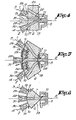
- the device is composed of two supply channels, 1 and 2 for the weft threads, respectively 3 and 4; a main blower 5 and an adjustable selector block 6 with a through channel 7.
- the selector block 6 is able to rotate about the symmetry axis 8 of the main blower 5 and is designed in such a way that it can rotate between, on one hand, the ends 9 and 10 of the supply channels 1 and 2 and, on the other hand, the inlet 11 of the main blower 5.
- the through channel 7 is mounted in the selector block 6 in such a way that the rotation of this block 6 can achieve quick connection between respectively the ends 9 and 10 and the inlet 11.
- means are provided in order to adjust the selector block 6 or, in other words, to rotate it in the case of this embodiment.
- These means may be of various kind and are compared, for instance, of a transmission on a shaft end 12 which is mounted on the selector block 6.
- the transmission may also occur by means of a driving mechanism located on the outside wall 13.
- the driving system as such, may be either electrical, electromagnetical, pneumatic or mechanical.
- Figure 2 shows another embodiment, whereby the supply channel, respectively 1 or 2, which is not connected to the inlet 11 of the main blower 5, is in connection with the surrounding atmosphere by means of a venting channel 14.
- the supply channel respectively 1 or 2 which is not connected to the inlet 11 of the main blower 5
- a venting channel 14 This way, it is permanently possible to convey an air jet or similar in the supply channels 1 and 2, in such a way that the free end 15 of the waiting weft thread, i.e. 3 or 4, is kept in drawn condition.
- the air stream used to keep the weft thread in drawn condition may be much smaller than the air stream which is existing during transport of the thread.
- Figure 3 illustrates still another embodiment, whereby several channels 16 and 17 are provided in the selector block 6 which all discharge before the inlet 11 of the main blower 5.
- This construction is advantageous because, if the yarn supply must be modified, the selector block has to be rotated only by a small angle A and such unlike the embodiment according to figure 1, whereby the selector block 6 must rotate by 180 degrees.
- the inlets respectively 18 and 19 of the channels 16 and 17, when they are not connected to one of the supply channels 1 or 2 may be closed by means not illustrated on the figure.
- This solution illustrated for instance by figure 3, avoids the pressure loss in the channel 17 created by the discharge of air along channel 16 and inlet 18.
- Figure 4 illustrates still another embodiment, whereby the selector block 6 is mounted with a possible sliding movement.
- the sliding direction is preferably in cross direction towards the symmetry axis 8 of the main blower 5.
- several through channels 20 to 22 are used.
- Figure 5 illustrates an embodiment whereby the selector block 6 can be moved by pivoting, for instance, in the guides 23 and 24. Quite obviously, in this embodiment as well as in the preceeding ones, venting openings, respectively 25, 26 and 27 may be provided, which in this case preferably discharge on the side of the selector block 6.
- Figure 6 illustrates still another embodiment, whereby the solution illustrated by figure 5 is comprising only one through channel 7.
- the number of supply channels may be also larger than two.
- three supply channels are provided, respectively 1, 2 and 28.
- the supply channels 1, 2 and 28 can preferably consist of the outlets of blowers, respectively 29, 30 and 31.
- thread squeezing devices may be mounted in the supply channels 1 and 2, for instance, exactly before or after the blowers involved, 29 and 30. In such a case, it is not necessary that the selector block 6 is equipped with a venting channel because the thread can be kept in drawn condition by adequate actuation of these thread squeezing devices 32 and 33.
- Also means may be provided, preferably in the various supply channels of the weft threads 3 and 4, in order to pull back the free end 15 of the waiting weft thread over a determined distance.
- These means may be of various kinds and are not specifically illustrated by the figures. They offer the advantage that the weft thread, i.e. thread 3 or thread 4 cannot be squeezed between the ends 9 and 10 of the supply channels 1 and 2.
- venting channels in the selector block 6 a small opening may be kept between the ends 9 and 10 of the supply channels 1 and 2 and the selector block 6 such in order to avoid squeezing the weft thread as already described.
- the invention is also concerning a method for supplying a weft thread into a shed.
- This method is mainly comprising the acceleration of the weft thread already before reaching the outlet of the main blower 5 and such preferably in order that the free end 15 of the involved weft thread is passing just at the moment of the beginning of the weft phase before the outlet of the main blower 5.
- the speed should be equal, at this moment, at least to the required injection speed.
- a really "flying start" of the weft thread is achieved with the advantage that a huge time saving is achieved and that weaving at high speed is made possible.
- the required speed of the thread can be achieved in the blowers.
- an actuating unit 34 is provided in order to cause the weft threads, respectively 3 and 4 starting at the right moments in order that their free ends, for instance the end 15, can reach the outlet of the main blower 5 at the adequate time referred to hereabove.
- the actuating unit 34 can be coupled, for instance, to this end, with the thread squeezing devices 32 and 33 or with the air supply, respectively 35 and 36, of the blowers 29 and 30 and, possibly, 31, mounted before the selector block 6.
- blowers which are mounted before and aftrer the selector block 6 may be of any kind.
- the present invention is by no means limited to the examples described hereabove and to the embodiments illustrated by the figures, but a device for supplying a weft thread to a main blower of weaving looms may be built with all kind of shapes and dimensions without leaving the scope of the invention.
Landscapes
- Engineering & Computer Science (AREA)
- Textile Engineering (AREA)
- Looms (AREA)
Claims (11)
Applications Claiming Priority (2)
| Application Number | Priority Date | Filing Date | Title |
|---|---|---|---|
| NL8503439 | 1985-12-13 | ||
| NL8503439A NL8503439A (nl) | 1985-12-13 | 1985-12-13 | Apparaat om een inslagdraad aan een hoofdblazer toe te voeren bij weefmachines. |
Publications (2)
| Publication Number | Publication Date |
|---|---|
| EP0225669A1 EP0225669A1 (de) | 1987-06-16 |
| EP0225669B1 true EP0225669B1 (de) | 1989-05-24 |
Family
ID=19847013
Family Applications (1)
| Application Number | Title | Priority Date | Filing Date |
|---|---|---|---|
| EP86202137A Expired EP0225669B1 (de) | 1985-12-13 | 1986-12-02 | Vorrichtung zur Zuführung des Schussfadens an die Hauptdüse einer Webmaschine |
Country Status (5)
| Country | Link |
|---|---|
| US (2) | US4756342A (de) |
| EP (1) | EP0225669B1 (de) |
| DE (1) | DE3663541D1 (de) |
| ES (1) | ES2008086B3 (de) |
| NL (1) | NL8503439A (de) |
Families Citing this family (19)
| Publication number | Priority date | Publication date | Assignee | Title |
|---|---|---|---|---|
| BE1000553A4 (nl) * | 1987-05-12 | 1989-01-31 | Picanol Nv | Werkwijze voor het bedraden van een inslaginrichting bij weefmachines, en inslaginrichting die deze werkwijze toepast. |
| EP0297040B1 (de) * | 1987-06-25 | 1991-06-26 | GebràDer Sulzer Aktiengesellschaft | Verfahren zum Eintragen von Schussfäden in eine pneumatische Mehrfarben-Webmaschine und Webmaschine zur Durchführung des Verfahrens |
| FR2644800B1 (fr) * | 1989-03-22 | 1991-05-31 | Saurer Diederichs Sa | Dispositif d'alimentation en fil de trame pour machine a tisser avec insertion pneumatique de la trame |
| FR2648831A1 (fr) * | 1989-06-26 | 1990-12-28 | Saurer Diederichs Sa | Dispositif d'alimentation en fil de trame pour machine a tisser avec insertion pneumatique |
| JP2848684B2 (ja) | 1989-11-16 | 1999-01-20 | ゲブリユーダー ズルツアー アクチエンゲゼルシヤフト | よこ糸分配機構 |
| US5462095A (en) * | 1993-02-08 | 1995-10-31 | Hokuriku Seikei Industrial Co., Ltd. | Picking device with selected spools for a water-jet loom |
| BE1006981A3 (nl) * | 1993-04-06 | 1995-02-07 | Picanol Nv | Insertiesysteem voor weefmachines. |
| DE29721042U1 (de) * | 1997-11-28 | 1998-02-05 | Dornier Gmbh Lindauer | Webmaschine, insbesondere Luftdüsenwebmaschine |
| DE29806552U1 (de) * | 1998-04-09 | 1998-07-09 | Dornier Gmbh Lindauer | Schußfadeneintragsvorrichtung für eine Luftdüsenwebmaschine |
| BE1012032A3 (nl) * | 1998-06-10 | 2000-04-04 | Picanol Nv | Luchttoevoerblok voor een weefmachine. |
| DE10224078A1 (de) * | 2002-05-31 | 2003-12-18 | Dornier Gmbh Lindauer | Verfahren zum Gestreckthalten eines Schussfadens und Webmaschine zur Verfahrensdurchführung |
| US6945282B2 (en) | 2002-06-17 | 2005-09-20 | Flora Gendelman | Method and device for forming a shed in a weaving machine |
| DE102005004064A1 (de) * | 2005-01-21 | 2006-07-27 | Picanol N.V. | Vorrichtung zum Eintragen von Schussfäden bei einer Luftdüsenwebmaschine |
| JP5216990B2 (ja) * | 2005-11-21 | 2013-06-19 | ピカノール | エアージェット式織機によこ糸を導入する方法とエアージェット式織機 |
| US7748414B2 (en) * | 2006-12-12 | 2010-07-06 | Itema (Switzerland) Ltd | Method and apparatus for the insertion of weft threads |
| CN102995235A (zh) * | 2012-11-26 | 2013-03-27 | 吴江市金真缝纫机有限公司 | 喷气织机可调压喷嘴 |
| CN103194846B (zh) * | 2013-04-16 | 2014-07-09 | 苏州大学 | 一种喷气型纺织机的主喷嘴结构及装配方法 |
| CN105821565B (zh) * | 2016-06-07 | 2017-12-08 | 青岛百佳机械有限公司 | 一种喷气织机引纬选纬装置 |
| WO2018161060A1 (en) | 2017-03-03 | 2018-09-07 | Ezer Vision L.L.C. | Variable color or texture expression knitting, weaving, and laminating system, method and fabric |
Family Cites Families (8)
| Publication number | Priority date | Publication date | Assignee | Title |
|---|---|---|---|---|
| US3482606A (en) * | 1966-06-18 | 1969-12-09 | Nissan Motor | Multi-weft fluid jet loom |
| US3853151A (en) * | 1971-01-08 | 1974-12-10 | Rueti Te Strake Bv | Weaving machine |
| CH556929A (de) * | 1972-10-09 | 1974-12-13 | Sulzer Ag | Webmaschine. |
| JPS5496168A (en) * | 1978-01-06 | 1979-07-30 | Nissan Motor | Weft yarn introducing apparatus air jet type loom |
| DE3203876A1 (de) * | 1982-02-05 | 1983-08-18 | Guenne Webmaschf Gmbh | Vorrichtung zum getrennten und/oder gemeinsamen einblasen verschiedenfarbiger schussfaeden bei luftduesen-webmaschinen |
| DE3204007A1 (de) * | 1982-02-05 | 1983-08-11 | Guenne Webmaschf Gmbh | Vorrichtung und verfahren zum einblasen verschiedenfarbiger schussfaeden bei luftduesen-webmaschinen |
| GB8316401D0 (en) * | 1983-06-16 | 1983-07-20 | Bonas Machine Co | Weaving loom |
| CS249259B1 (en) * | 1983-08-01 | 1987-03-12 | Frantisek Vykydal | Pick insertion device for jet loom |
-
1985
- 1985-12-13 NL NL8503439A patent/NL8503439A/nl not_active Application Discontinuation
-
1986
- 1986-12-02 EP EP86202137A patent/EP0225669B1/de not_active Expired
- 1986-12-02 ES ES86202137T patent/ES2008086B3/es not_active Expired
- 1986-12-02 DE DE8686202137T patent/DE3663541D1/de not_active Expired
- 1986-12-12 US US06/940,971 patent/US4756342A/en not_active Expired - Fee Related
-
1988
- 1988-04-26 US US07/186,287 patent/US4850398A/en not_active Expired - Lifetime
Also Published As
| Publication number | Publication date |
|---|---|
| US4850398A (en) | 1989-07-25 |
| US4756342A (en) | 1988-07-12 |
| EP0225669A1 (de) | 1987-06-16 |
| ES2008086B3 (es) | 1989-07-16 |
| NL8503439A (nl) | 1987-07-01 |
| DE3663541D1 (en) | 1989-06-29 |
Similar Documents
| Publication | Publication Date | Title |
|---|---|---|
| EP0225669B1 (de) | Vorrichtung zur Zuführung des Schussfadens an die Hauptdüse einer Webmaschine | |
| US4326565A (en) | Apparatus for inserting successive weft yarn lengths in a shuttleless weaving machine | |
| US5146955A (en) | Filling thread distributor mechanism for a series-shed weaving machine | |
| US3926224A (en) | Weft selecting, measuring and storing apparatus | |
| US3831640A (en) | Pneumatic loom | |
| EP0418948B1 (de) | Blasvorrichtung für die Schussfäden in Webmaschinen | |
| US4542772A (en) | Apparatus for selectively introducing one or more of a plurality of different weft threads into an air jet weaving machine | |
| IT9020598A1 (it) | Dispositivo di presentazione della trama per telai di tessitura a pinze | |
| US3395737A (en) | Pneumatic filling inserter | |
| US5417250A (en) | Weft insertion system for air-jet loom | |
| US3319663A (en) | Means for supplying shuttles of looms with thread and apparatus therefor | |
| US3796236A (en) | Weft thread inserting means | |
| EP0626476B1 (de) | Steuersystem für eine Vorrichtung zur Herstellung von Einlegekanten in Webmaschinen, insbesondere in Webmaschinen für durch Variation der Rietanschlagposition hergestellte Frottiergewebe | |
| SU1192631A3 (ru) | Устройство дл управлени соплами пневматического ткацкого станка | |
| US4494577A (en) | Weft inserting device for jet looms | |
| US4411294A (en) | Method and apparatus for inserting weft filaments | |
| EP0291486B1 (de) | Verfahren und Vorrichtung zum Einfädeln des Schusseintragorgans in Webmaschinen | |
| US5247968A (en) | Projectile loom having a composite material multiple weft device | |
| US3902530A (en) | Projectile picking means for a pneumatic loom | |
| US3868976A (en) | Pneumatic weft inserting mechanism | |
| US3853151A (en) | Weaving machine | |
| EP1777330A1 (de) | Verfahren zur Abstützung eines Schussfadenführungselements | |
| US5419370A (en) | Griper welf inserter switching device | |
| US4625771A (en) | Apparatus for inserting two weft threads into two warp sheds in a loom with central jet insertion | |
| CS247373B1 (en) | Device for picking of two wefts into two sheds on weaving loom with central jet picking |
Legal Events
| Date | Code | Title | Description |
|---|---|---|---|
| PUAI | Public reference made under article 153(3) epc to a published international application that has entered the european phase |
Free format text: ORIGINAL CODE: 0009012 |
|
| AK | Designated contracting states |
Kind code of ref document: A1 Designated state(s): BE CH DE ES FR GB IT LI LU NL |
|
| 17P | Request for examination filed |
Effective date: 19870622 |
|
| 17Q | First examination report despatched |
Effective date: 19880614 |
|
| GRAA | (expected) grant |
Free format text: ORIGINAL CODE: 0009210 |
|
| AK | Designated contracting states |
Kind code of ref document: B1 Designated state(s): BE CH DE ES FR GB IT LI LU NL |
|
| ITF | It: translation for a ep patent filed | ||
| REF | Corresponds to: |
Ref document number: 3663541 Country of ref document: DE Date of ref document: 19890629 |
|
| ET | Fr: translation filed | ||
| PLBE | No opposition filed within time limit |
Free format text: ORIGINAL CODE: 0009261 |
|
| STAA | Information on the status of an ep patent application or granted ep patent |
Free format text: STATUS: NO OPPOSITION FILED WITHIN TIME LIMIT |
|
| 26N | No opposition filed | ||
| PGFP | Annual fee paid to national office [announced via postgrant information from national office to epo] |
Ref country code: GB Payment date: 19901130 Year of fee payment: 5 |
|
| PGFP | Annual fee paid to national office [announced via postgrant information from national office to epo] |
Ref country code: ES Payment date: 19901213 Year of fee payment: 5 |
|
| PGFP | Annual fee paid to national office [announced via postgrant information from national office to epo] |
Ref country code: NL Payment date: 19901231 Year of fee payment: 5 |
|
| PGFP | Annual fee paid to national office [announced via postgrant information from national office to epo] |
Ref country code: LU Payment date: 19910109 Year of fee payment: 5 |
|
| EPTA | Lu: last paid annual fee | ||
| PG25 | Lapsed in a contracting state [announced via postgrant information from national office to epo] |
Ref country code: LU Free format text: LAPSE BECAUSE OF NON-PAYMENT OF DUE FEES Effective date: 19911202 Ref country code: GB Effective date: 19911202 |
|
| PG25 | Lapsed in a contracting state [announced via postgrant information from national office to epo] |
Ref country code: ES Free format text: LAPSE BECAUSE OF EXPIRATION OF PROTECTION Effective date: 19911203 |
|
| ITTA | It: last paid annual fee | ||
| PG25 | Lapsed in a contracting state [announced via postgrant information from national office to epo] |
Ref country code: NL Effective date: 19920701 |
|
| GBPC | Gb: european patent ceased through non-payment of renewal fee | ||
| NLV4 | Nl: lapsed or anulled due to non-payment of the annual fee | ||
| PGFP | Annual fee paid to national office [announced via postgrant information from national office to epo] |
Ref country code: FR Payment date: 19921117 Year of fee payment: 7 |
|
| PGFP | Annual fee paid to national office [announced via postgrant information from national office to epo] |
Ref country code: BE Payment date: 19921118 Year of fee payment: 7 |
|
| PGFP | Annual fee paid to national office [announced via postgrant information from national office to epo] |
Ref country code: CH Payment date: 19921120 Year of fee payment: 7 |
|
| PGFP | Annual fee paid to national office [announced via postgrant information from national office to epo] |
Ref country code: DE Payment date: 19930114 Year of fee payment: 7 |
|
| PG25 | Lapsed in a contracting state [announced via postgrant information from national office to epo] |
Ref country code: LI Effective date: 19931231 Ref country code: CH Effective date: 19931231 Ref country code: BE Effective date: 19931231 |
|
| BERE | Be: lapsed |
Owner name: PICANOL N.V. Effective date: 19931231 |
|
| PG25 | Lapsed in a contracting state [announced via postgrant information from national office to epo] |
Ref country code: FR Effective date: 19940831 |
|
| REG | Reference to a national code |
Ref country code: CH Ref legal event code: PL |
|
| PG25 | Lapsed in a contracting state [announced via postgrant information from national office to epo] |
Ref country code: DE Effective date: 19940901 |
|
| REG | Reference to a national code |
Ref country code: FR Ref legal event code: ST |
|
| REG | Reference to a national code |
Ref country code: ES Ref legal event code: FD2A Effective date: 20010301 |
|
| PG25 | Lapsed in a contracting state [announced via postgrant information from national office to epo] |
Ref country code: IT Free format text: LAPSE BECAUSE OF NON-PAYMENT OF DUE FEES;WARNING: LAPSES OF ITALIAN PATENTS WITH EFFECTIVE DATE BEFORE 2007 MAY HAVE OCCURRED AT ANY TIME BEFORE 2007. THE CORRECT EFFECTIVE DATE MAY BE DIFFERENT FROM THE ONE RECORDED. Effective date: 20051202 |