EP0225213B1 - Ununterbrochene Fördereinrichtung mit veränderlicher Geschwindigkeit - Google Patents
Ununterbrochene Fördereinrichtung mit veränderlicher Geschwindigkeit Download PDFInfo
- Publication number
- EP0225213B1 EP0225213B1 EP86402332A EP86402332A EP0225213B1 EP 0225213 B1 EP0225213 B1 EP 0225213B1 EP 86402332 A EP86402332 A EP 86402332A EP 86402332 A EP86402332 A EP 86402332A EP 0225213 B1 EP0225213 B1 EP 0225213B1
- Authority
- EP
- European Patent Office
- Prior art keywords
- supports
- variable
- speed
- transport device
- speed continuous
- Prior art date
- Legal status (The legal status is an assumption and is not a legal conclusion. Google has not performed a legal analysis and makes no representation as to the accuracy of the status listed.)
- Expired
Links
- 238000006073 displacement reaction Methods 0.000 claims description 3
- 230000005540 biological transmission Effects 0.000 description 3
- 241000826860 Trapezium Species 0.000 description 1
- 230000000694 effects Effects 0.000 description 1
- 230000009931 harmful effect Effects 0.000 description 1
- 238000012986 modification Methods 0.000 description 1
- 230000004048 modification Effects 0.000 description 1
Images
Classifications
-
- B—PERFORMING OPERATIONS; TRANSPORTING
- B66—HOISTING; LIFTING; HAULING
- B66B—ELEVATORS; ESCALATORS OR MOVING WALKWAYS
- B66B21/00—Kinds or types of escalators or moving walkways
- B66B21/10—Moving walkways
- B66B21/12—Moving walkways of variable speed type
Definitions
- variable speed continuous transport devices such as variable speed conveyor belts, which essentially consist of load-bearing elements such as plates, overlapped and mounted on supports, the speed variation being obtained by varying the distance between the neighboring supports, each pair of neighboring supports being connected by means of a deformable link, such as a chain or a belt, which passes over angle transmission elements, such as sprockets or pulleys, which are mounted on said supports with the possibility of translation controlled perpendicular to the direction of movement of the transport device, so as to vary the distance between the two supports; these angle transmission elements are guided in their translation by guides such as rails along the path of the system.
- Such devices are described in particular in French patents FR-A 2 190 690 and FR-A 2 202 828.
- Such a device makes it possible for example to produce moving walkways at variable speed, the speed being low in the access and exit zones and high over the majority of the course of the treadmills.
- the device is driven on a few supports in the high-speed area. Due to the elasticity and wear of the link (a chain can admit a variation in length of the order of 2% during its lifetime), the connection between the neighboring supports is not carried out geometrically rigorous and this is particularly troublesome in high-speed areas and, more particularly, in the support drive areas because the distance between the supports is not strictly maintained and it is in particular difficult to distribute the effort correctly. training on several neighboring supports.
- the subject of the present invention is a continuous variable speed transport device as defined above in which, in the zones at maximum speed, the distance between the neighboring supports is strictly maintained.
- each pair of neighboring supports is also connected by means of at least one device with free articulation in the form of a compass, the adjustment of the translation of said angle transmission elements being such that at maximum speed, that is to say for the maximum distance of the supports, said free articulation device is at its maximum opening and the deformable link is substantially relaxed, the connection between the two neighboring supports then being ensured by said free articulation device.
- connection is ensured by a rigid mechanical device, which ensures precise relative positioning of the supports and therefore in particular makes it possible to better distribute the driving force over several neighboring supports.
- said free articulation device further comprises a articulation allowing a movement of one branch of the compass relative to the other in a direction perpendicular to the plane of said free articulation device.
- This arrangement makes it possible in particular to absorb the movements of change of slope of the moving walkway.
- this articulation is a ball joint.
- one of the branches of the compass constituting the free articulation device comprises an extension beyond the top of said compass, said extension constituting a stop cooperating with a stop secured to the other branch of the compass .
- the distance between the two supports is very precisely defined using the two abovementioned stops. It is advantageous for these two stops to have planar contact surfaces in order to obtain better relative positioning of the two arms of the compass.
- two devices are provided with free articulation between each pair of neighboring supports, these two devices being arranged in planes parallel to the plane of movement of the transport device and distinct.
- the use of two devices makes it possible to strengthen the connection between two supports and the fact of having them in two separate planes makes it possible to reduce the space occupied by these devices with free articulation.
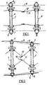
- FIGS. 1 and 2 two neighboring plate supports 1 and 2 are seen which are connected together by means of a deformable link 3 constituted for example by a chain forming an endless loop.
- Each support 1 consists of a tube 4 through which the above-mentioned deformable elements 3 pass and which comprises at each of its ends two control heads 5 and 6. These two guide heads are mounted to slide in the tube 4 and carry angle gear elements constituted by pinions 7, each head comprising two pinions, one for each chain 3 passing through the tube 4.
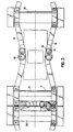
- These control heads are guided by means of a roller 8 which rolls along a track guide 9 shown in FIG. 2.
- Each support pulling the support which follows it, the deformable element 3 is tensioned so as to form a trapezoid of constant perimeter and variable bases.
- This device of known type is described in particular in French patent 2 202 828, it can be used for example for the production of a moving sidewalk at variable speed; this sidewalk is made up of plates mounted with overlap and supported at one of their ends by a support 1 or 2. In low-speed zones, the plates overlap almost completely whereas in high-speed zones they have a very low covering surface.
- connection between two neighboring supports 1 and 2 at least one device with free articulation in the form of a compass 11; the two "points" of the compass 11 are articulated respectively on the two adjacent supports 1 and 2 and the two branches of the compass are articulated around the apex 12.
- the compass 11 when one is in a high-speed zone , as shown in Figure 1, the heads 5 and 6 being retracted as far as possible into the tubes 4, the compass 11 is at its maximum opening and the adjustment of the control ramps 9 of the heads 5 and 6 is such that the chain 3 is substantially relaxed so that the connection between the neighboring supports 1 and 2 is carried out by the mechanical device 11.
- the maximum opening of the compass 11 is determined by means of a stop integral with one of the two branches of the compass and coming into abutment on the other branch.
- this makes it possible to precisely determine the relative position of the two supports 1 and 2 and to prevent the compass 11 from overturning.
- the mechanical connection produced by the compass 11 therefore makes it possible to produce a rigid and precise connection in high-speed areas, which makes it possible to obtain a precise positioning of the supports so that it is easier to distribute the drive force. on several neighboring supports at the moving side drive device.
- the compasses 11 play a safety role in the event that the deformable link 3 breaks; in fact, if the chain 3 breaks in any area at low or high speed, the connection between the two neighboring supports will then be ensured by the compass 11.
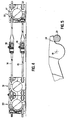
- Figures 3 and 4 show an embodiment of the invention; in these figures, we see in the central part two supports 31 and 32 in the position corresponding to a high-speed zone, that is to say with a maximum spacing, and, on the left part of these figures, two supports 33 and 31 shown in their low speed position, that is to say with minimum spacing.
- the articulation of the apex 18 of each of the compasses 14 and 15 is such that it allows a slight relative displacement of the two branches relative to each other in a plane perpendicular to their plane, that is to say in a vertical plane in the case of Figures 3 and 4; this arrangement makes it possible to absorb the deformations due to the change of slope passages.
- This is particularly important in the case where the transport device is a continuous loop device. Indeed, at the entrance and at the exit of the moving walkway, the plates descend below the ground, and the treadmill makes a 180 ° rotation in its plane to set off again in the other direction.
- this articulation is of the ball type.
- one of the arms of the compass 11, 14 or 15 has an extension extending beyond the top constituting the joint 18; this extension 19 constitutes a stop which cooperates with a stop 21 of the other branch of the compass.
- this arrangement ensures good stability of the opening length of the compass 11, 14 or 15 in high-speed zones where it is he who provides the connection between the neighboring supports.
- the two stops 19 and 21 have two flat surfaces in their contact zones, which further increases the precision of the relative positioning of the two arms of the compass in the high-speed zones and increases the rigidity of the connection between the two neighboring supports. .
- the above description has been provided by way of illustrative and in no way limitative example and it is obvious that it is possible to make modifications of variants without thereby departing from the scope of the present invention.
- the number and the position of the free-jointing devices can be varied.
- the invention applies to any continuous transport device in which the connection between two supports of neighboring carrier elements is carried out by means of any deformable element which can for example be a belt or a cable.
- This deformable element may not consist of a loop but be fixed at its two ends and the geometrical figure described by said deformable element may be arbitrary and is not limited to a quadrilateral.
Landscapes
- Escalators And Moving Walkways (AREA)
- Vending Machines For Individual Products (AREA)
- Supplying Of Containers To The Packaging Station (AREA)
- Attitude Control For Articles On Conveyors (AREA)
- Control Of Conveyors (AREA)
Claims (7)
Priority Applications (1)
| Application Number | Priority Date | Filing Date | Title |
|---|---|---|---|
| AT86402332T ATE40338T1 (de) | 1985-10-21 | 1986-10-17 | Ununterbrochene foerdereinrichtung mit veraenderlicher geschwindigkeit. |
Applications Claiming Priority (2)
| Application Number | Priority Date | Filing Date | Title |
|---|---|---|---|
| FR8515591A FR2588842B1 (fr) | 1985-10-21 | 1985-10-21 | Dispositif de transport en continu a vitesse variable |
| FR8515591 | 1985-10-21 |
Publications (2)
| Publication Number | Publication Date |
|---|---|
| EP0225213A1 EP0225213A1 (de) | 1987-06-10 |
| EP0225213B1 true EP0225213B1 (de) | 1989-01-25 |
Family
ID=9324041
Family Applications (1)
| Application Number | Title | Priority Date | Filing Date |
|---|---|---|---|
| EP86402332A Expired EP0225213B1 (de) | 1985-10-21 | 1986-10-17 | Ununterbrochene Fördereinrichtung mit veränderlicher Geschwindigkeit |
Country Status (8)
| Country | Link |
|---|---|
| US (1) | US4732257A (de) |
| EP (1) | EP0225213B1 (de) |
| JP (1) | JPS62100309A (de) |
| AT (1) | ATE40338T1 (de) |
| CA (1) | CA1230072A (de) |
| DE (1) | DE3661902D1 (de) |
| FR (1) | FR2588842B1 (de) |
| SU (1) | SU1537130A3 (de) |
Families Citing this family (8)
| Publication number | Priority date | Publication date | Assignee | Title |
|---|---|---|---|---|
| FR2631324A1 (fr) * | 1988-05-13 | 1989-11-17 | Chabiland Michel | Trottoir roulant a acceleration et deceleration |
| JPH07100595B2 (ja) * | 1988-12-21 | 1995-11-01 | 三菱電機株式会社 | 中間高速移動歩道 |
| US4953685A (en) * | 1989-08-10 | 1990-09-04 | Otis Elevator Company | Step chain for curved escalator |
| JP2540965B2 (ja) * | 1990-01-16 | 1996-10-09 | 三菱電機株式会社 | 中間高速エスカレ―タ― |
| US6044955A (en) * | 1997-02-14 | 2000-04-04 | Inventio Ag | Accelerating travelling walkway with laterally and longitudinally displaceable step plates |
| US6138816A (en) * | 1998-06-19 | 2000-10-31 | Nkk Corporation | Variable-speed passenger conveyer and handrail device thereof |
| NL1009569C2 (nl) * | 1998-07-06 | 2000-01-10 | Food Processing Systems | Eindloze transporteur. |
| DE102006009491A1 (de) | 2006-02-27 | 2007-09-06 | Busak + Shamban Deutschland Gmbh | Dichtungssystem mit Druckentlastungselementen und Verwendung eines Dichtungssystems zur Einstellung einer Zwischenraumdruckkaskade |
Family Cites Families (13)
| Publication number | Priority date | Publication date | Assignee | Title |
|---|---|---|---|---|
| CH468292A (fr) * | 1966-07-06 | 1969-02-15 | Battelle Development Corp | Dispositif transporteur |
| US3516363A (en) * | 1968-01-24 | 1970-06-23 | Jurjen Van Der Wal | Conveyor system with portions operable at different speeds |
| US3565238A (en) * | 1968-05-06 | 1971-02-23 | Basil J Candela | Variable-velocity conveyor |
| BE756837R (fr) * | 1969-09-30 | 1971-03-01 | Pirelli | Trottoir roulant |
| FR2076180A1 (fr) * | 1970-01-05 | 1971-10-15 | Patin Pierre | Perfectionnement apporté aux roulements anti-friction et ses applications, notamment en convoyage. |
| FR2202828B1 (de) * | 1972-10-13 | 1977-04-01 | Patin Pierre | |
| ES415246A1 (es) * | 1972-06-30 | 1976-07-16 | Patin | Dispositivo para el arrastre a velocidad variable de ele- mentos moviles. |
| FR2207069B1 (de) * | 1972-11-22 | 1977-04-08 | Regie Autonome Transports | |
| US4053044A (en) * | 1974-06-14 | 1977-10-11 | Pierre Patin | System for continuous entrainment at variable speed |
| JPS5424793A (en) * | 1977-07-27 | 1979-02-24 | Yoshio Tachikawa | See through rod within water |
| JPS5437758A (en) * | 1977-08-30 | 1979-03-20 | Ricoh Co Ltd | Electrostatic latent image developing method |
| FR2431075A1 (fr) * | 1978-07-11 | 1980-02-08 | Regie Autonome Transports | Chaine a un seul sens de courbure et application a une main courante |
| FR2443955A1 (fr) * | 1978-12-13 | 1980-07-11 | Cesbron Lavau Rene | Dispositif de dilatation-contraction associe a un ensemble lineaire en defilement, et application aux trottoirs roulants |
-
1985
- 1985-10-21 FR FR8515591A patent/FR2588842B1/fr not_active Expired
-
1986
- 1986-10-17 AT AT86402332T patent/ATE40338T1/de not_active IP Right Cessation
- 1986-10-17 EP EP86402332A patent/EP0225213B1/de not_active Expired
- 1986-10-17 JP JP61248262A patent/JPS62100309A/ja active Pending
- 1986-10-17 DE DE8686402332T patent/DE3661902D1/de not_active Expired
- 1986-10-20 SU SU864028360A patent/SU1537130A3/ru active
- 1986-10-20 CA CA000520845A patent/CA1230072A/en not_active Expired
- 1986-10-21 US US06/921,096 patent/US4732257A/en not_active Expired - Fee Related
Also Published As
| Publication number | Publication date |
|---|---|
| CA1230072A (en) | 1987-12-08 |
| US4732257A (en) | 1988-03-22 |
| FR2588842A1 (fr) | 1987-04-24 |
| ATE40338T1 (de) | 1989-02-15 |
| EP0225213A1 (de) | 1987-06-10 |
| DE3661902D1 (en) | 1989-03-02 |
| JPS62100309A (ja) | 1987-05-09 |
| FR2588842B1 (fr) | 1987-12-31 |
| SU1537130A3 (ru) | 1990-01-15 |
Similar Documents
| Publication | Publication Date | Title |
|---|---|---|
| EP0225213B1 (de) | Ununterbrochene Fördereinrichtung mit veränderlicher Geschwindigkeit | |
| EP0014298B1 (de) | Umlaufende Fördereinrichtung mit örtlich unterschiedlichen Geschwindigkeiten und Anwendung für Rollsteige | |
| FR2835034A1 (fr) | Dispositif de decharge d'efforts pour chaines porte-cables | |
| EP0907550B1 (de) | Spann-und führungseinrichtung für ketten der gangschaltung für fahrräder | |
| EP0468841B1 (de) | Bandförderer | |
| EP0034980B1 (de) | Reinigungs-, Verlade- und Sortiervorrichtung für Gemüse oder Früchte | |
| FR2792921A1 (fr) | Repartiteur de produits pour installation de convoyage | |
| FR2693280A1 (fr) | Dispositif mobile de déplacement et de positionnement d'un ou de plusieurs appareils optiques. | |
| FR2810653A1 (fr) | Dispositif accumulateur en u pour reguler le transfert de produits entre un appareil amont et un appareil aval | |
| EP0104110A2 (de) | Kettenumsetzer für Fahrradantriebszahnkranz | |
| FR2683213A1 (fr) | Dispositif de convoyage d'objets legers et instables. | |
| FR2868760A1 (fr) | Dispositif de convoyage a courroie vrillee deux fois et a poulie de tension flottante | |
| FR3005237A1 (fr) | Machine de ramassage de fruits comprenant une chenille perfectionnee et procede de conversion d'une machine de recoltage | |
| FR2483736A1 (fr) | Faucheuse | |
| FR2675007A1 (fr) | Dispositif de collecte et de convoyage de baies et fruits dans une machine de recolte. | |
| EP0250330B1 (de) | Vorrichtung zur Verlängerung von Brotteig | |
| FR2607120A1 (fr) | Transporteur a bande entrainee par chaine | |
| FR2638602A1 (fr) | Machine a vendanger | |
| FR2466195A1 (fr) | Dispositif permettant le deplacement lateral d'articles de boulangerie, notamment des pains, sur une bande transporteuse | |
| FR2463045A1 (fr) | Derailleur pour cycle | |
| FR2757143A1 (fr) | Agencement de main-courante pour trottoir roulant et utilisations de celui-ci | |
| CH399309A (fr) | Transporteur | |
| FR2491898A1 (fr) | Dispositif de changement de direction pour transporteur a bande | |
| EP0919494A1 (de) | Verfahren und Vorrichtung zum Positionieren von Produkten auf einem aus zwei Förderern bestehenden Transfertsystem | |
| FR2619797A1 (fr) | Dispositif de transfert utilisable entre deux transporteurs sans fin |
Legal Events
| Date | Code | Title | Description |
|---|---|---|---|
| PUAI | Public reference made under article 153(3) epc to a published international application that has entered the european phase |
Free format text: ORIGINAL CODE: 0009012 |
|
| AK | Designated contracting states |
Kind code of ref document: A1 Designated state(s): AT BE CH DE GB IT LI LU NL SE |
|
| 17P | Request for examination filed |
Effective date: 19870729 |
|
| 17Q | First examination report despatched |
Effective date: 19880331 |
|
| GRAA | (expected) grant |
Free format text: ORIGINAL CODE: 0009210 |
|
| AK | Designated contracting states |
Kind code of ref document: B1 Designated state(s): AT BE CH DE GB IT LI LU NL SE |
|
| REF | Corresponds to: |
Ref document number: 40338 Country of ref document: AT Date of ref document: 19890215 Kind code of ref document: T |
|
| ITF | It: translation for a ep patent filed | ||
| GBT | Gb: translation of ep patent filed (gb section 77(6)(a)/1977) | ||
| REF | Corresponds to: |
Ref document number: 3661902 Country of ref document: DE Date of ref document: 19890302 |
|
| PG25 | Lapsed in a contracting state [announced via postgrant information from national office to epo] |
Ref country code: AT Effective date: 19891017 |
|
| PG25 | Lapsed in a contracting state [announced via postgrant information from national office to epo] |
Ref country code: SE Effective date: 19891018 |
|
| PG25 | Lapsed in a contracting state [announced via postgrant information from national office to epo] |
Ref country code: LU Free format text: LAPSE BECAUSE OF NON-PAYMENT OF DUE FEES Effective date: 19891031 Ref country code: LI Effective date: 19891031 Ref country code: CH Effective date: 19891031 Ref country code: BE Effective date: 19891031 |
|
| PLBE | No opposition filed within time limit |
Free format text: ORIGINAL CODE: 0009261 |
|
| STAA | Information on the status of an ep patent application or granted ep patent |
Free format text: STATUS: NO OPPOSITION FILED WITHIN TIME LIMIT |
|
| 26N | No opposition filed | ||
| BERE | Be: lapsed |
Owner name: ALSTHOM Effective date: 19891031 Owner name: REGIE AUTONOME DES TRANSPORTS PARISIENS Effective date: 19891031 |
|
| PG25 | Lapsed in a contracting state [announced via postgrant information from national office to epo] |
Ref country code: NL Effective date: 19900501 |
|
| NLV4 | Nl: lapsed or anulled due to non-payment of the annual fee | ||
| REG | Reference to a national code |
Ref country code: CH Ref legal event code: PL |
|
| PGFP | Annual fee paid to national office [announced via postgrant information from national office to epo] |
Ref country code: GB Payment date: 19901008 Year of fee payment: 5 |
|
| PGFP | Annual fee paid to national office [announced via postgrant information from national office to epo] |
Ref country code: DE Payment date: 19901027 Year of fee payment: 5 |
|
| ITTA | It: last paid annual fee | ||
| PG25 | Lapsed in a contracting state [announced via postgrant information from national office to epo] |
Ref country code: GB Effective date: 19911017 |
|
| GBPC | Gb: european patent ceased through non-payment of renewal fee | ||
| PG25 | Lapsed in a contracting state [announced via postgrant information from national office to epo] |
Ref country code: DE Effective date: 19920701 |
|
| EUG | Se: european patent has lapsed |
Ref document number: 86402332.0 Effective date: 19900706 |
|
| PG25 | Lapsed in a contracting state [announced via postgrant information from national office to epo] |
Ref country code: IT Free format text: LAPSE BECAUSE OF NON-PAYMENT OF DUE FEES;WARNING: LAPSES OF ITALIAN PATENTS WITH EFFECTIVE DATE BEFORE 2007 MAY HAVE OCCURRED AT ANY TIME BEFORE 2007. THE CORRECT EFFECTIVE DATE MAY BE DIFFERENT FROM THE ONE RECORDED. Effective date: 20051017 |