EP0224948B1 - Granulatfilter - Google Patents
Granulatfilter Download PDFInfo
- Publication number
- EP0224948B1 EP0224948B1 EP86201926A EP86201926A EP0224948B1 EP 0224948 B1 EP0224948 B1 EP 0224948B1 EP 86201926 A EP86201926 A EP 86201926A EP 86201926 A EP86201926 A EP 86201926A EP 0224948 B1 EP0224948 B1 EP 0224948B1
- Authority
- EP
- European Patent Office
- Prior art keywords
- filter according
- pistons
- base part
- granular
- granular filter
- Prior art date
- Legal status (The legal status is an assumption and is not a legal conclusion. Google has not performed a legal analysis and makes no representation as to the accuracy of the status listed.)
- Expired
Links
- 239000008187 granular material Substances 0.000 title description 34
- 238000004140 cleaning Methods 0.000 claims description 10
- 238000000034 method Methods 0.000 claims description 8
- 238000007664 blowing Methods 0.000 claims description 2
- 238000005192 partition Methods 0.000 claims description 2
- 239000012530 fluid Substances 0.000 claims 2
- 238000011001 backwashing Methods 0.000 description 7
- 238000005299 abrasion Methods 0.000 description 4
- 238000010926 purge Methods 0.000 description 3
- 238000005056 compaction Methods 0.000 description 1
- 238000010276 construction Methods 0.000 description 1
- 238000011161 development Methods 0.000 description 1
- 230000018109 developmental process Effects 0.000 description 1
- 230000000694 effects Effects 0.000 description 1
- 238000011086 high cleaning Methods 0.000 description 1
- 239000012535 impurity Substances 0.000 description 1
- 238000012423 maintenance Methods 0.000 description 1
- 239000002245 particle Substances 0.000 description 1
- 238000010079 rubber tapping Methods 0.000 description 1
Images


Classifications
-
- B—PERFORMING OPERATIONS; TRANSPORTING
- B01—PHYSICAL OR CHEMICAL PROCESSES OR APPARATUS IN GENERAL
- B01D—SEPARATION
- B01D46/00—Filters or filtering processes specially modified for separating dispersed particles from gases or vapours
- B01D46/30—Particle separators, e.g. dust precipitators, using loose filtering material
Definitions
- the invention relates to a granulate filter for horizontal gas passage with two gas-permeable walls arranged vertically at a distance from one another, a frame consisting of a base part and two side parts, connected to the walls, and a granulate fill in the space formed by the frame and the walls, as well as a process for cleaning the granulate bed by backwashing.
- the granulate bed is cleaned outside the filter in a special cleaning chamber, the granules either being cleaned in batches at intervals or by the granules continuously circulating through the filter space and the cleaning chamber.
- cleaning processes require complex transport devices for the granulate, which are only required for a short time in batch operation and are very susceptible to faults or require maintenance because of the long downtimes and the frequent switching on and off.
- continuous circulation all affected parts of the apparatus are subject to heavy wear.
- the granulate experiences a relatively strong abrasion, which changes the filter characteristics and increases the gas-side flow resistance.
- the granulate bed can be loosened during the cleaning by backwashing, whereby the cleaning can be significantly improved compared to backwashing when the granulate bed is not moved.
- the stroke height and stroke speed of the piston can be matched to the respective requirements, which means that an economic optimum can be achieved in each individual case, i.e. at the same time high cleaning effect and low granular abrasion.
- the invention provides that the granulate bed is loosened before and / or during backwashing by moving the pistons up and down.
- Advantageous variations of the method result from claims 15 to 17.
- the granulate filter for horizontal gas passage according to FIG. 1 has two gas-permeable walls 1 and 2 arranged vertically at a distance from one another, each with a perforated plate 1 a, 2a and a wire screen 1b, 2b matched to the granulate particles.
- the gas-permeable walls 1 and 2 together with the frame 3 open at the top form a space in which the granulate bed 4 is arranged.
- the wall parts and the granulate fill are only partially shown.
- perforated plate 2a, wire sieve 2b, granular bed 4, wire sieve 1b and perforated plate 1a follow one another from front to back in the illustration.
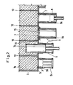
- openings 7 are arranged in the bottom part 5 of the frame 3 and can be closed in a granulate-tight manner by pistons 6 which can be moved up and down.
- the granulate bed is divided into walls by partitions 10, each of which is assigned an opening 7 with a piston 6.
- the pistons are shown from the left in FIG. 2 only for the second and fourth chambers.
- FIG. 2 has a different embodiment of the piston and the piston guide for the first and second chambers than for the chambers 3 and 4. This representation has been chosen in order not to have to unnecessarily increase the number of drawings. In practice, of course, the same embodiment will be chosen for all chambers of a granulate filter.
- FIG. 3 shows a simplified view and a simplified horizontal section of the exemplary embodiment, supplemented by a drive for the pistons.
- the perforated plate 1a has a cover 12 in the upper part, by means of which the uppermost region of the granulate bed is blocked for the passage of gas. In this way it is ensured that the gas does not have any granule-free cross-sectional areas that it could flow through uncleaned, moreover with less pressure loss.
- a plurality of chambers 11 are formed by intermediate walls 10 within the side walls of the frame 3, to which an opening 7 with piston guide 9a and piston 6 is assigned in the base part.
- a crankshaft is provided for the up and down movement, which can be set in rotation by a drive 13.
- Such an embodiment requires that the granulate beds in all chambers of a granulate filter are simultaneously loosened, i.e. that the granulate filter is cleaned in this case by means of backwashing.
- hydraulic or pneumatic individual drives can also be provided for the pistons, so that the chambers can be cleaned one after the other in conjunction with a corresponding gas-side shut-off, the granulate filter remaining operational otherwise.
Landscapes
- Chemical & Material Sciences (AREA)
- Chemical Kinetics & Catalysis (AREA)
- Filtering Of Dispersed Particles In Gases (AREA)
- Glanulating (AREA)
- Filtration Of Liquid (AREA)
Description
- Die Erfindung bezieht sich auf ein Granulatfilter für horizontalen Gasdurchtritt mit zwei im Abstand zueinander vertikal angeordneten, gasdurchlässigen Wänden, einem aus einem Bodenteil und zwei Seitenteilen bestehenden, mit den Wänden verbundenem Rahmen und einer Granulatschüttung in dem aus dem Rahmen und den Wänden gebildeten Raum sowie auf ein Verfahren zur Reinigung der Granulatschüttung durch Rückspülung.
- Die Reinigung der Granulatschüttung erfolgt bei herkömmlichen Filtern dieser Art außerhalb des Filters in einer besonderen Reinigungskammer, wobei das Granulat entweder in zeitlichen Abständen chargenweise gereinigt wird oder indem das Granulat kontinuierlich durch den Filterraum und die Reinigungskammer umläuft. Derartige Reinigungsverfahren erfordern aufwendige Transporteinrichtungen für das Granulat, die bei chargenweisem Betrieb immer nur kurzfristig benötigt werden und wegen der langen Stillstandszeiten und des häufigen Ein- und Ausschaltens sehr störanfällig bzw. wartungsbedürftig sind. Bei kontinuierlichem Umlauf unterliegen alle betroffenen Apparateteile einem starken Verschleiß. Außerdem erfährt das Granulat einen verhältnismäßig starken Abrieb, durch den die Filtercharakteristik verändert und eine Erhöhung des gasseitigen Strömungwiderstandes bewirkt wird.
- Es ist daher auch schon vorgeschlagen worden, die Granulatschüttung für die Reinigung im Filter zu belassen, den Gasdurchgang abzusperren und mit gereinigtem Gas oder einem anderen Medium rückzuspülen. Auf diese Weise können aber die aus dem Gas abgeschiedenen und auf dem Granulat abgelagerten Verunreinigungen nur unvollkommen entfernt werden. Eine gewisse Verbesserung kann erreicht werden, wenn die Granulatschüttung während der Rückspülung durch Klopfwerke oder dergleichen erschüttert wird. Nachteilig ist aber, daß jede Erschütterung des Filterbettes mit einem gewissen Granulatabrieb verbunden ist und zwangsläufig zu einer Verdichtung der Schüttung führt, wodurch ebenfalls die Filtercharakteristik verändert und der Strömungswiderstand erhöht wird.
- Es besteht somit die Aufgabe, ein Granulatfilter der eingangs genannten Art so zu gestalten, daß die vorgenannten Nachteile vermieden werden können. Insbesondere soll die Reinigung der Granulatschüttung mittels Rückspülung mit möglichst geringem Granulatabrieb verbunden sein, wenig Energieaufwand erfordern und keine Veränderung der Filtercharakteristik oder Vergrößerung des Strömungswiderstandes mit sich bringen.
- Diese Aufgabe wird erfindungsgemäß dadurch gelöst, daß bei einem gattungsmäßigen Granulatfilter im Bodenteil des Rahmens wenigstens eine, durch einen auf und ab bewegbaren Kolben granulatdicht verschlossene Öffnung angeordnet ist.
- Durch die Kolbenbewegung kann die Granulatschüttung während der Reinigung durch Rückspülung aufgelockert werden, wodurch die Abreinigung im Vergleich zu einer Rückspülung bei unbewegter Granulatschüttung wesentlich verbessert werden kann. Hubhöhe und Hubgeschwindigkeit des Kolbens können auf die jeweiligen Bedürfnisse abgestimmt werden, wodurch sich in jedem Einzelfall ein wirtschaftliches Optimum erreichen läßt, d.h. gleichzeitig hohe Abreinigungswirkung und geringer Granulatabrieb.
- Zweckmäßige Weiterbildungen des Erfindungsgedankens sind in den Ansprüchen 2 bis 13 beschrieben.
- Bei dem Verfahren zum Betreiben des Granulatfilters ist erfindungsgemäß vorgesehen, daß die Granulatschüttung vor und/oder während der Rückspülung durch Auf- und Abbewegen der Kolben aufgelockert wird. Vorteilhafte Variationen des Verfahrens ergeben sich aus den Ansprüchen 15 bis 17.
- Weitere Einzelheiten und Vorteile des Erfindungsgedankens werden anhand des in den Figuren dargestellten Ausführungsbeispiels näher erläutert.
- Figur 1 zeigt in perspektivischer Darstellung den prinzipiellen Aufbau eines Granulatfilters.
- Figur 2 zeigt in einem vertikalen Teilschnitt die Anordnung der Bodenöffnungen und Kolben.
- Figur 3 zeigt Ansicht und horizontalen Schnitt eines vereinfacht dargestellten Granulatfilters mit Kurbelantrieb für die Kolben.
- Das Granulatfilter für horizontalen Gasdurchtritt gemäß Figur 1 besitzt zwei im Abstand zueinander vertikal angeordnete gasdurchlässige Wände 1 und 2 mit jeweils einem Lochblech 1 a, 2a sowie einem auf die Granulatpartikel abgestimmten Drahtsieb 1b, 2b. Die gasdurchlässigen Wände 1 und 2 bilden zusammen mit dem nach oben offenen Rahmen 3 einen Raum, in dem die Granulatschüttung 4 angeordnet ist. Zur Verdeutlichung des Aufbaus sind die Wandteile und die Granulatschüttung nur teilweise dargestellt. In Gasströmungsrichtung folgen in der Darstellung von vorn nach hinten aufeinander Lochblech 2a, Drahtsieb 2b, Granulatschüttung 4, Drahtsieb 1 b und Lochblech 1a.
- Aus der Darstellung gemäß Figur 2 ist ersichtlich, wie im Bodenteil 5 des Rahmens 3 Öffnungen 7 angeordnet sind, die durch auf und ab bewegbare Kolben 6 granulatdicht verschlossen werden können. Die Granulatschüttung ist durch Zwischenwände 10 in Kammern unterteilt, denen je eine Öffnung 7 mit Kolben 6 zugeordnet ist. Zum besseren Verständnis sind die Kolben in Figur 2 nur für die zweite und vierte Kammer von links dargestellt.
- Die Kolbenführungen 9 können entweder in Form von sich vom Bodenteil 5 aus nach unten erstreckenden Zylindern 9a oder in Form von kurzen Zylindern 9b mit sich daran anschließenden Stegen 9c ausgebildet sein. Dementsprechend können entweder Kolben mit einer Mantelhöhe H von 0,4 bis 0,5 D (= Kolbendurchmesser) oder aber mit einer Mantelhöhe H von 2,5 bis 3 D vorgesehen sein. 1 b bezeichnet wieder das ausgangsseitige Drahtsieb des hier ohne Granulatfüllung dargestellten vertikalen Teilschnitts des Granulatfilters. Ferner ist vorgesehen, daß entweder die Kolben 6 oder die Kolbenführungen 9 Bohrungen 14, 15 zum Einblasen von Spülluft in den Raum zwischen Kolben 6 und Kolbenführung 9 aufweisen. Die Zufuhr der Spülluft an die Kolbenführung erfolgt durch eine Ringleitung 16. Für die Zuführung von Spülluft an den Kolben, die in Figur 2 im einzelnen nicht dargestellt ist, können aus dem Motorenbau bekannte Vorrichtungen verwendet werden.
- Es sei noch darauf hingewiesen, daß Figur 2 für die erste und zweite Kammer eine andere Ausführungsform des Kolbens und der Kolbenführung aufweist als für die Kammern 3 und 4. Diese Darstellungsweise ist gewählt worden, um die Zahl der Zeichnungen nicht unnötig erhöhen zu müssen. In der Praxis wird man selbstverständlich die gleiche Ausführungsform für alle Kammern eines Granulatfilters wählen.
- In Figur 3 ist eine vereinfachte Ansicht und ein vereinfachter Horizontalschnitt des Ausführungsbeispiels, ergänzt durch einen Antrieb für die Kolben, dargestellt. Das Lochblech 1a weist im oberen Teil eine Abdeckung 12 auf, mittels derer der oberste Bereich der Granulatschüttung für den Gasdurchgang gesperrt ist. Auf diese Weise wird sichergestellt, daß dem Gas keine granulatfreien Querschnittsbereiche zur Verfügung stehen, die es - zudem bei geringerem Druckverlust - ungereinigt durchströmen könnte. Durch Zwischenwände 10 sind innerhalb der Seitenwände des Rahmens 3 mehrere Kammern 11 gebildet, denen im Bodenteil je eine Öffnung 7 mit Kolbenführung 9a und Kolben 6 zugeordnet ist. Für die Auf- und Abbewegung ist eine Kurbelwelle vorgesehen, die über einen Antrieb 13 in Drehbewegung versetzt werden kann. Eine derartige Ausführungsform bedingt, daß gleichzeitig die Granulatschüttungen in allen Kammern eines Granulatfilters der Auflockerung unterworfen werden, d.h. daß das Granulatfilter in diesem Fall insgesamt mittels Rückspülung gereinigt wird. Selbstverständlich können auch hydraulische oder pneumatische Einzelantriebe für die Kolben vorgesehen werden, so daß - in Verbindung mit einer entsprechenden gasseitigen Teilabsperrung - die Kammern nacheinander gereinigt werden können, wobei das Granulatfilter im übrigen betriebsbereit bleibt. Neben der weitgehend freien Wahl des Kolbenhubs und der Kolbengeschwindigkeit, ist damit eine weitere Möglichkeit geschaffen, die es erlaubt, den Erfindungsgedanken an die Bedingungen des Einzelfalls anzupassen.
Claims (17)
Applications Claiming Priority (2)
| Application Number | Priority Date | Filing Date | Title |
|---|---|---|---|
| DE19853541174 DE3541174A1 (de) | 1985-11-21 | 1985-11-21 | Granulatfilter |
| DE3541174 | 1985-11-21 |
Publications (2)
| Publication Number | Publication Date |
|---|---|
| EP0224948A1 EP0224948A1 (de) | 1987-06-10 |
| EP0224948B1 true EP0224948B1 (de) | 1989-04-19 |
Family
ID=6286477
Family Applications (1)
| Application Number | Title | Priority Date | Filing Date |
|---|---|---|---|
| EP86201926A Expired EP0224948B1 (de) | 1985-11-21 | 1986-11-05 | Granulatfilter |
Country Status (4)
| Country | Link |
|---|---|
| US (1) | US4702751A (de) |
| EP (1) | EP0224948B1 (de) |
| JP (1) | JPS62129123A (de) |
| DE (2) | DE3541174A1 (de) |
Families Citing this family (3)
| Publication number | Priority date | Publication date | Assignee | Title |
|---|---|---|---|---|
| US4840651A (en) * | 1988-01-11 | 1989-06-20 | Tigg Corporation | Gas/solids contacting device |
| GB2268094A (en) * | 1992-06-12 | 1994-01-05 | Stork Protecon Bv | Filter for a gas stream, especially from a fluidised bed |
| JP6559025B2 (ja) * | 2015-09-14 | 2019-08-14 | 日本製鉄株式会社 | 触媒反応装置及び触媒反応方法 |
Family Cites Families (2)
| Publication number | Priority date | Publication date | Assignee | Title |
|---|---|---|---|---|
| US3564570A (en) * | 1968-03-08 | 1971-02-16 | Fuller Co | Gas-solids separator |
| SU1084051A1 (ru) * | 1982-12-27 | 1984-04-07 | Волго-Уральский научно-исследовательский и проектный институт по добыче и переработке сероводородсодержащих газов | Адсорбер |
-
1985
- 1985-11-21 DE DE19853541174 patent/DE3541174A1/de not_active Withdrawn
-
1986
- 1986-11-05 DE DE8686201926T patent/DE3662840D1/de not_active Expired
- 1986-11-05 EP EP86201926A patent/EP0224948B1/de not_active Expired
- 1986-11-18 US US06/932,190 patent/US4702751A/en not_active Expired - Fee Related
- 1986-11-19 JP JP61276395A patent/JPS62129123A/ja active Pending
Also Published As
| Publication number | Publication date |
|---|---|
| US4702751A (en) | 1987-10-27 |
| EP0224948A1 (de) | 1987-06-10 |
| DE3541174A1 (de) | 1987-05-27 |
| DE3662840D1 (en) | 1989-05-24 |
| JPS62129123A (ja) | 1987-06-11 |
Similar Documents
| Publication | Publication Date | Title |
|---|---|---|
| DE3235552C2 (de) | Rückspülfilter | |
| DE69208358T2 (de) | Vorrichtung zur gleichmässigen Verteilung von Gas und/oder Flüssigkeit in einem seitlichen Unterdrainagesystem | |
| DE3905963C2 (de) | Polymer-Filtervorrichtung | |
| DE2231904C3 (de) | Automatischer kontinuierlicher Gegenstromwaschfilter | |
| DE4012404C1 (de) | ||
| EP1423178B1 (de) | Vorrichtung zum filtrieren eines fluids, insbesondere für kunststoffverarbeitende anlagen | |
| DE1436287A1 (de) | Verfahren zum Filtern eines Fluids und Anlage zur Durchfuehrung des Verfahrens | |
| DE3727277A1 (de) | Verfahren und vorrichtung zum filtern einer fluessigkeit | |
| DE3138676A1 (de) | Filtereinrichtung mit einer einrichtung zum rueckspuelen des filterbettes | |
| DE60016463T2 (de) | Fluidregelventil und platte mit einem filter | |
| EP0438685A1 (de) | Former in einer Papiermaschine | |
| EP0361217B1 (de) | Rückspülfilter | |
| DE2455904B2 (de) | Vorrichtung zum Trennen eines Gemisches von Flüssigkeiten verschiedener spezifischer Gewichte | |
| EP0224948B1 (de) | Granulatfilter | |
| DE68913136T2 (de) | Verfahren zur zyklischen Zubereitung von Käsemassensträngen und Vorrichtung zur Ausführung dieses Verfahrens. | |
| DE9105000U1 (de) | Siebwechselkassette | |
| DE2003368A1 (de) | Rundstrickmaschine | |
| DE2130501A1 (de) | Vorrichtung zum Auswechseln von Sieben | |
| DE1461512A1 (de) | Filterpresse | |
| DE1131162B (de) | Siebrost | |
| DE69827215T2 (de) | Statische Anlage zum Filtern von Flüssigkeiten | |
| DE69319206T2 (de) | Anlage zum automatischen Reinigen von Plattenfilterpressen | |
| EP0245869B1 (de) | Vorrichtung zum Vermischen von Mehrkomponentenkunststoffen, insbesondere Polyurethan | |
| DE8717960U1 (de) | Labyrinthfilter für das Dielektrikum von Erodieranlagen | |
| DE76194C (de) | Filter mit beweglichen, das zusamroendrückbare Filtermaterial umschliefsenden Siebplatten |
Legal Events
| Date | Code | Title | Description |
|---|---|---|---|
| PUAI | Public reference made under article 153(3) epc to a published international application that has entered the european phase |
Free format text: ORIGINAL CODE: 0009012 |
|
| AK | Designated contracting states |
Kind code of ref document: A1 Designated state(s): CH DE FR GB IT LI |
|
| 17P | Request for examination filed |
Effective date: 19870708 |
|
| 17Q | First examination report despatched |
Effective date: 19880907 |
|
| GRAA | (expected) grant |
Free format text: ORIGINAL CODE: 0009210 |
|
| AK | Designated contracting states |
Kind code of ref document: B1 Designated state(s): CH DE FR GB IT LI |
|
| REF | Corresponds to: |
Ref document number: 3662840 Country of ref document: DE Date of ref document: 19890524 |
|
| ET | Fr: translation filed | ||
| ITF | It: translation for a ep patent filed | ||
| GBT | Gb: translation of ep patent filed (gb section 77(6)(a)/1977) | ||
| PLBE | No opposition filed within time limit |
Free format text: ORIGINAL CODE: 0009261 |
|
| STAA | Information on the status of an ep patent application or granted ep patent |
Free format text: STATUS: NO OPPOSITION FILED WITHIN TIME LIMIT |
|
| 26N | No opposition filed | ||
| PGFP | Annual fee paid to national office [announced via postgrant information from national office to epo] |
Ref country code: FR Payment date: 19910917 Year of fee payment: 6 |
|
| PGFP | Annual fee paid to national office [announced via postgrant information from national office to epo] |
Ref country code: GB Payment date: 19911024 Year of fee payment: 6 |
|
| ITTA | It: last paid annual fee | ||
| PGFP | Annual fee paid to national office [announced via postgrant information from national office to epo] |
Ref country code: CH Payment date: 19911216 Year of fee payment: 6 |
|
| PG25 | Lapsed in a contracting state [announced via postgrant information from national office to epo] |
Ref country code: GB Effective date: 19921105 |
|
| PG25 | Lapsed in a contracting state [announced via postgrant information from national office to epo] |
Ref country code: LI Effective date: 19921130 Ref country code: CH Effective date: 19921130 |
|
| GBPC | Gb: european patent ceased through non-payment of renewal fee |
Effective date: 19921105 |
|
| PG25 | Lapsed in a contracting state [announced via postgrant information from national office to epo] |
Ref country code: FR Effective date: 19930730 |
|
| REG | Reference to a national code |
Ref country code: CH Ref legal event code: PL |
|
| REG | Reference to a national code |
Ref country code: FR Ref legal event code: ST |
|
| PGFP | Annual fee paid to national office [announced via postgrant information from national office to epo] |
Ref country code: DE Payment date: 19941221 Year of fee payment: 9 |
|
| PG25 | Lapsed in a contracting state [announced via postgrant information from national office to epo] |
Ref country code: DE Effective date: 19951129 |
|
| PG25 | Lapsed in a contracting state [announced via postgrant information from national office to epo] |
Ref country code: IT Free format text: LAPSE BECAUSE OF NON-PAYMENT OF DUE FEES;WARNING: LAPSES OF ITALIAN PATENTS WITH EFFECTIVE DATE BEFORE 2007 MAY HAVE OCCURRED AT ANY TIME BEFORE 2007. THE CORRECT EFFECTIVE DATE MAY BE DIFFERENT FROM THE ONE RECORDED. Effective date: 20051105 |