EP0224428B1 - Enclosed shoe press - Google Patents
Enclosed shoe press Download PDFInfo
- Publication number
- EP0224428B1 EP0224428B1 EP86630173A EP86630173A EP0224428B1 EP 0224428 B1 EP0224428 B1 EP 0224428B1 EP 86630173 A EP86630173 A EP 86630173A EP 86630173 A EP86630173 A EP 86630173A EP 0224428 B1 EP0224428 B1 EP 0224428B1
- Authority
- EP
- European Patent Office
- Prior art keywords
- belt
- shoe
- nip
- beyond
- connection
- Prior art date
- Legal status (The legal status is an assumption and is not a legal conclusion. Google has not performed a legal analysis and makes no representation as to the accuracy of the status listed.)
- Expired - Lifetime
Links
- 239000000314 lubricant Substances 0.000 claims description 12
- XLYOFNOQVPJJNP-UHFFFAOYSA-N water Substances O XLYOFNOQVPJJNP-UHFFFAOYSA-N 0.000 claims description 8
- 239000000463 material Substances 0.000 claims description 4
- 239000003921 oil Substances 0.000 description 16
- 239000003595 mist Substances 0.000 description 9
- 238000003825 pressing Methods 0.000 description 9
- 239000012530 fluid Substances 0.000 description 4
- 230000008859 change Effects 0.000 description 3
- 230000006872 improvement Effects 0.000 description 3
- 230000001050 lubricating effect Effects 0.000 description 3
- 230000007246 mechanism Effects 0.000 description 2
- 230000000717 retained effect Effects 0.000 description 2
- 238000010276 construction Methods 0.000 description 1
- 230000003292 diminished effect Effects 0.000 description 1
- 230000000694 effects Effects 0.000 description 1
- 230000008030 elimination Effects 0.000 description 1
- 238000003379 elimination reaction Methods 0.000 description 1
- 239000000835 fiber Substances 0.000 description 1
- 239000010687 lubricating oil Substances 0.000 description 1
- 230000013011 mating Effects 0.000 description 1
- 238000000034 method Methods 0.000 description 1
- 238000012986 modification Methods 0.000 description 1
- 230000004048 modification Effects 0.000 description 1
- 230000002028 premature Effects 0.000 description 1
- 238000004904 shortening Methods 0.000 description 1
- 239000007787 solid Substances 0.000 description 1
Images
Classifications
-
- D—TEXTILES; PAPER
- D21—PAPER-MAKING; PRODUCTION OF CELLULOSE
- D21C—PRODUCTION OF CELLULOSE BY REMOVING NON-CELLULOSE SUBSTANCES FROM CELLULOSE-CONTAINING MATERIALS; REGENERATION OF PULPING LIQUORS; APPARATUS THEREFOR
- D21C7/00—Digesters
-
- D—TEXTILES; PAPER
- D21—PAPER-MAKING; PRODUCTION OF CELLULOSE
- D21F—PAPER-MAKING MACHINES; METHODS OF PRODUCING PAPER THEREON
- D21F3/00—Press section of machines for making continuous webs of paper
- D21F3/02—Wet presses
- D21F3/0209—Wet presses with extended press nip
- D21F3/0218—Shoe presses
-
- D—TEXTILES; PAPER
- D21—PAPER-MAKING; PRODUCTION OF CELLULOSE
- D21F—PAPER-MAKING MACHINES; METHODS OF PRODUCING PAPER THEREON
- D21F3/00—Press section of machines for making continuous webs of paper
- D21F3/02—Wet presses
-
- D—TEXTILES; PAPER
- D21—PAPER-MAKING; PRODUCTION OF CELLULOSE
- D21F—PAPER-MAKING MACHINES; METHODS OF PRODUCING PAPER THEREON
- D21F3/00—Press section of machines for making continuous webs of paper
- D21F3/02—Wet presses
- D21F3/0209—Wet presses with extended press nip
- D21F3/0218—Shoe presses
- D21F3/0227—Belts or sleeves therefor
- D21F3/0245—Means for fixing the sleeve to the roller end
Definitions
- the present invention relates to improvements in presses for mechanically pressing water from a traveling web in a paper machine, and more particularly of the press of the type known as an extended nip press.
- an extended nip press the length of a single nip in the machine direction extends substantially longer than the nip of a conventional type formed between two mating rolls.
- the invention relates to improvements in means for containing lubricant which is used to provide a wedge of lubricating film between the shoe and belt in an extended nip press of the type which employs a concave shoe urged toward a supporting roll to form a nip with the shoe urged toward the nip and the shoe supported in a manner so that it will be self- positioning to maintain the wedge of lubricant.
- Extended nip presses of this type have been formed in various arrangements with one type of arrangement disclosed and illustrated in Justus U.S. Patent 3,783,097.
- oil is employed as a lubricant between the shoe and belt. Oil will form a wedge that will not break down under normal operating speeds.
- This type of press is particularly advantageous in extending the time to which a sheet of paper is exposed to pressing pressure within the nip. It is also advantageous in that the invention of this press permits control of the pressure profile within the nip. Optimum pressing and variations in pressure profile can be attained by varying the location of the shoe relative to its support and by changing the curvature of the shoe.
- DE-A 3 338 487 A similar approach in pressing water from a travelling web in a paper machine is disclosed in DE-A 3 338 487.
- an extended nip press for removing water from a travelling web in a paper machine comprising a looped belt which passes through a nip formed between a concave shoe and a roll, the looped belt extending beyond the lateral ends of the shoe, with the shoe urged toward the roll in a manner to permit the shoe to tilt and form a wedge of lubricant between the shoe and the belt, annular end walls for the ends of the belt beyond the lateral ends of the shoe for containing lubricant within the belt, and an annular connection between the end walls and the belt having substantial flexibility in the radial plane of the end walls so that the belt can flex beyond the lateral ends of the shoe, the connection being formed of a double walled material having a radial dimension greater than the space between the outer edge of the end wall and the belt.
- the object of the invention is to provide an improved shoe type press utilizing an improved apparatus for containing oil within a looped belt of the press by providing an end wall which is connected to the belt in such a manner that it permits the belt to follow the single plane of curvature of the nip beyond the ends of the nip thereby avoiding the disadvantages of an end wall structure such as that employed in the prior art, while providing a flexible annular connection which may be clamped to the ends of the belt so as to facilitate flexure of the belt beyond the lateral ends of the shoe.
- a feature of the invention is the provision of an apparatus for containing lubricant within a looped belt of a shoe type press without shortening the life of the belt due to its flexing in a double plane at the ends of the nip.
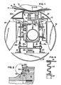
- the mechanism includes a press roll 10 which may be a solid roll or a roll having deflection control means such as provided by a hollow roll shell with a controllable support therein opposite the nip.
- the roll 10 forms a nip with a shoe 11.
- the shoe 11 is provided with a concave surface facing the roll and is mounted so that as it is urged toward the roll, a press nip N is formed therebetween which subjects a web of paper W passing through the nip to a pressing pressure over an extended length of time.
- a looped belt 12 passes through the nip between the shoe 11 and roll 10.
- a hydrodynamic wedge of fluid builds up between the belt and the shoe to transmit pressure to the web passing through the nip and press water from the web.
- the pressure profile to which the web is subjected in passing through the nip can be controlled.
- the pressure profile should provide for a gradual increase in pressure in the nip sufficient to build up to a desired nip pressure as rapidly as possible without causing crushing or dislocation of the fibers.
- this pressure is held for a period of time until near the end of the shoe at which a rapid pressure drop-off is permitted.
- the rapid drop-off aids in preventing rewetting of the web as it leaves the nip.
- This pressure profile is taught by the method disclosed in U.S. Patent 3,808,092, Busker.
- Means are provided for receiving water pressed from the web in the form of felts 13 and 14 which sandwich the web therebetween. It may also be desired to provide grooves in the surface of the roll 10 and in the surface of the belt 12 to aid in permitting the water to pass into the felts and to be retained thereby.
- the shoe is supported and is urged toward the nip to provide a pressing force.
- the shoe is tiltably or pivotally supported such as on a roll pin 16 seated in a downwardly facing groove in the shoe 11 and an upwardly facing groove in a piston 17.
- the piston is urged upwardly by fluid pressure beneath the piston in a chamber 18 which is in the form of an elongate slot or well slidably receiving the piston extending the full width of the machine beneath the shoe.
- the shoe may be supported in various ways such as to be tiltable and be self-positionable as it is urged up toward the backing roll 10.
- the wedge of lubricating fluid is permitted to be built up in the nip without breaking down which would cause consequent scuffing of the inner surface of the belt 12.
- Lubricating fluid preferably in the form of oil, is supplied to a relieved nose at the leading end of the piston through a lubricant supply 15.
- the cross-machine width of the nip depends upon the width of the machine desired by the papermaker and the roll 10, shoe 11 and its support mechanism will extend for the full width of the machine so as to continually press a wide web W passing through the nip.
- the belt is structured in the form of a continuous loop.
- the loop is permitting to travel in operation in its natural shape as shown and taught by U.S. Patent 4,287,021, Justus et al and its reissue Re31,923.
- guide means are provided for the belt which support it and guide it during start-up of the machine and which provide a support for the belt when the belt encounters instability during operation.
- the looped belt is of considerable weight and fluttering or instability can occur at high speeds so that guides are provided within the belt to again stabilize the belt if this instability should occur during normal operation.
- the belt should start fluttering such as due to the disturbances outside the belt or unexpected unequal distribution of oil within the belt, the fluttering will be dampened and corrected so that the belt can return to traveling in its natural free form unsupported shape where there is a very small space between the guide and belt.
- These guide means for the belt are shown in the form of curved side guides 19 and 20, and upper guides 22 and 22a and a lower guide 21. While guides are shown as being of some appreciable length, shorter guides, or guides with greater spacing therebetween or even axially extended guide bars with rounded ends may be used with the guides positioned so that they lie on a circle defining the natural free from running shape of the belt.
- the belt guides 19 and 20 are supported for adjustment so that they can be adjusted to provide a very small gap between the outer smooth surfaces of the guides and the belt during normal free form operation.
- the guides are carried on the central beam 38 and are mounted so as to be adjustable in position to maintain the very small gap between the inner surface of the belt and the outer smooth surface of the guides during the natural free form operation.
- the lower shoe 21 is supported on pins 27 and 28 carried on a crossbar 28a on the beam.
- the vertical pins extend through openings in the crossbar and have springs 27a and 28b urging the pins in an upwardly direction.
- An air inflatable bellows 28c is located between the beam and shoe and by controlling the inflation in the bellows through an air connection, not shown, the position of the shoe 21 relative to the inner surface of the belt can be adjusted.
- the side shoe 20 is mounted on brackets 20a and 20b on the beam 38.
- the side shoe 19 is mounted on brackets 19a and 19b on the beam 38.
- Brackets 19a, 19b, 20a and 20b permit adjustment to control the lateral position of the shoes 19 and 20 so that they can be positioned correctly. relative to the free form of the inner surface of the belt.
- the upper shoes 22 and 22a are adjustably supported on brackets with bolts 22b and 22c on the beam so that they can be accurately adjusted and located relative to the free form shape of the belt.
- the lower shoe 21, the side shoes 19 and 20, and the upper shoes 22 and 22a are all adjusted so as to provide a continual support for the belt.
- the shoes are adjusted so that a very small gap exists between their outer smooth surface and the belt as the belt runs in its free form during operation. Minor disturbances in operation can, of course, disturb the free form of the belt. Such disturbances as change in stock, change in stock temperature, wads passing through the nip, and unevenness in the thickness of the felts will disturb the perfection of the travel of the belt in its ideal free form.
- drive means not shown, is provided for the backup roll 10 and its frictional contact through the felts 13 and 14 drives the belt.
- the shoe is then loaded up against the belt and the lubricating oil delivered through the supplies 15 provides for the build-up of a wedge of oil between the shoe and the belt.
- oil which may be left within the belt is pumped out from within the belt by a line having an intake near the lower shoe 21. This line continues to remove extra oil from within the belt during operation.
- the belt starts up, it is guided by the smooth outer surfaces of the shoes 19, 20, 21, 22 and 22a and as it attains operating speed, centrifugal force causes it to attain its natural free form shape so that it runs unsupported by the guides.
- end walls 33 are provided at the ends of the looped annular belt.
- the beam 38 has end hubs 32 extending beyond the end walls, and the end walls are positioned to be supported coaxial on the circular end hubs 32 by having annular bearings 34 between the end walls and the hubs 32 of the beam.
- circular end walls have been connected to the annular ends of the belt and such walls have been the same diameter as the belt such that they cause the belt to retain a circular shape at the ends beyond the end of the nip.
- These end walls have taken the form of plates with clamping rings which are bolted to the circular belt.
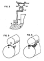
- the belt need to flex only in a single plane as shown in Fig. 6. Essentially no constraint is placed on the ends of the belt in a radial direction so that it may curve in a concave curve all the way to the end in the manner shown in Fig. 6 which may be referred to as single plane flexure. It will be apparent that this results in considerable less stress on the belt in the area at the ends of the nip.
- seals at the ends of the endless belt which permit the belt to freely flex in the plane of the roll beyond the ends of the shoe.
- the end walls which are provided offer substantially no resistance to the belt flexing in this roll plane while still maintaining the integrity of the closure at the end of the belt.
- annular end wall 33 is provided supported on bearings 34 mounted on the hub 32 of the beam.
- This end wall is of a diameter less than the belt and is connected to the ends of the belt by a flexible yieldable connection between the outer edge of the end wall and the outer end of the belt.
- the soft yieldable connector 35, Figs 2 and 3 maintains the oil mist integrity of the end wall and yet does not offer resistance to the belt following the arc of flexure in the nip.
- the seal or connector 35 has a double accordion wall with an outer wall shown at 35a and an inner wall at 35b. The inner edges of the wall are connected at 37 to the end wall 33 and at their outer edges 36 to the belt.
- Figure 4 illustrates another form of connector 45 which is an undulated shaped flexible wall which extends from the outer edge of the end wall 33 to the outer edge of the belt 12.
- the flexible annular connector 45 may be provided with an inwardly facing groove 46 so as to receive the end of the belt and may be clamped thereto such as being sewn to draw the sides of the groove 46 tightly against the belt 12.
- the inner radial edge of the connector 45 may be provided with a T-shaped base 47 for securing to the end wall. If desired, the connector 45 may be of substantial radial depth so that it connects directly to the bearing 34 which rides on the hub 32.
- annular connectors or seal may be employed which provide a soft flexible mist impervious connection.
- the radial depth of the connectors must be sufficient to permit flexing of the belt to follow the curvature of the nip as illustrated in Fig. 5.
- the radius of the outer edge of the circular end walls is at least as small as the radius from the center of the belt to the working face of the shoe and preferably smaller.
- the total radius of the end wall and connector is equal to the radius of the belt. It is contemplated that the entire end wall may be made flexible but in the preferred arrangement, a more rigid end wall is used with a flexible annular outer connector portion.
- mist formed within the looped belt will be retained therein by the end wall and the rotating belt seal. Yet, during rotation, the belt will be permitted to flex and follow the curvature of the nip, changing its arc of curvature from the natural shape to the nip shape while passing through the nip. At the entering end of the nip, the belt begins to follow the curvature of the nip and at the trailing end of the shoe, the belt again follows the natural shape. This occurs over the entire width of the belt beyond the nip end and the sole flexure which the belt must encounter is in the single plane. This permits design and construction for maximum strength in the expected single plane of flexure.
- the improved stable travel of the belt substantially enhances the operating life of the belt eliminating the need for frequent replacement
- the advantages of the shoe type extended nip press can be attained and the speed of operation, viscosity of oil, and press nip pressures can be chosen solely for optimum performance and without concern to the possible generation of an oil mist.
- This also permits elimination of mist preventing seals around the shoe and permits the use of a looped belt, and the diminished power requirement in permitting the belt to travel during operation at its natural free form shape, without concern as to the escape of oil mist.
Landscapes
- Paper (AREA)
Applications Claiming Priority (2)
| Application Number | Priority Date | Filing Date | Title |
|---|---|---|---|
| US801317 | 1985-11-25 | ||
| US06/801,317 US4673461A (en) | 1985-11-25 | 1985-11-25 | Enclosed shoe press with flexible end connections for its annular belt |
Publications (2)
| Publication Number | Publication Date |
|---|---|
| EP0224428A1 EP0224428A1 (en) | 1987-06-03 |
| EP0224428B1 true EP0224428B1 (en) | 1990-10-31 |
Family
ID=25180779
Family Applications (1)
| Application Number | Title | Priority Date | Filing Date |
|---|---|---|---|
| EP86630173A Expired - Lifetime EP0224428B1 (en) | 1985-11-25 | 1986-11-20 | Enclosed shoe press |
Country Status (13)
| Country | Link |
|---|---|
| US (1) | US4673461A (pl) |
| EP (1) | EP0224428B1 (pl) |
| JP (1) | JPS62125089A (pl) |
| KR (1) | KR900002103B1 (pl) |
| CN (1) | CN1017636B (pl) |
| AR (1) | AR245245A1 (pl) |
| BR (1) | BR8605706A (pl) |
| CA (1) | CA1271353A (pl) |
| DE (1) | DE3675344D1 (pl) |
| ES (1) | ES2018476B3 (pl) |
| MX (1) | MX162287A (pl) |
| PH (1) | PH22366A (pl) |
| PL (1) | PL157214B1 (pl) |
Cited By (1)
| Publication number | Priority date | Publication date | Assignee | Title |
|---|---|---|---|---|
| DE19645407A1 (de) * | 1996-11-04 | 1998-05-07 | Voith Sulzer Papiermasch Gmbh | Schuhpresse |
Families Citing this family (29)
| Publication number | Priority date | Publication date | Assignee | Title |
|---|---|---|---|---|
| DE3708189A1 (de) * | 1987-03-13 | 1988-09-22 | Voith Gmbh J M | Langspalt-walzenpresse |
| DE3708191A1 (de) * | 1987-03-13 | 1988-09-22 | Voith Gmbh J M | Nasspresse |
| US4741805A (en) * | 1987-07-23 | 1988-05-03 | Beloit Corporation | Guiding apparatus for guiding an extended nip press blanket |
| DE3808293C2 (de) * | 1988-03-12 | 1994-08-18 | Voith Gmbh J M | Langspalt-Preßwalze |
| US4861434A (en) * | 1988-10-21 | 1989-08-29 | Beloit Corporation | Extended nip press apparatus with tracks to slideably accommodate beaded blanket edges |
| US4877472A (en) * | 1988-10-31 | 1989-10-31 | Beloit Corporation | Method of making a bearing blanket |
| FI82092C (fi) * | 1989-03-22 | 1991-01-10 | Valmet Paper Machinery Inc | Laongnyppress. |
| US4975152A (en) * | 1989-07-06 | 1990-12-04 | Beloit Corporation | Enclosed extended nip press apparatus with inflatable seals and barbs |
| WO1992008003A1 (en) * | 1990-10-31 | 1992-05-14 | Beloit Corporation | Paper web heating on a press roll |
| DE4415645A1 (de) * | 1994-05-04 | 1995-11-09 | Voith Sulzer Papiermasch Gmbh | Walze für eine Papiermaschine |
| US5556514A (en) * | 1995-05-26 | 1996-09-17 | Beloit Technologies, Inc. | Extended nip press apparatus with geared blanket edge clamp |
| DE19615654A1 (de) * | 1996-04-19 | 1997-10-23 | Voith Sulzer Papiermasch Gmbh | Pressenanordnung |
| DE19642401A1 (de) * | 1996-10-14 | 1998-04-16 | Voith Sulzer Papiermasch Gmbh | Pressenanordnung |
| US5700357A (en) * | 1996-10-16 | 1997-12-23 | Beloit Technologies, Inc. | Mechanical blanket clamp in rotating head assembly |
| DE19703218A1 (de) * | 1997-01-29 | 1998-07-30 | Voith Sulzer Papiermasch Gmbh | Preßvorrichtung, insbesondere für eine Papiermaschine |
| US5897747A (en) * | 1997-08-08 | 1999-04-27 | Beloit Technologies, Inc. | Machine direction profiling of extended nip press shoe |
| US5882483A (en) * | 1998-06-10 | 1999-03-16 | Beloit Technologies, Inc. | Extended nip press apparatus |
| US6332953B1 (en) | 1998-10-02 | 2001-12-25 | International Paper Company | Paper product having enhanced printing properties and related method of manufacture |
| US6248210B1 (en) | 1998-11-13 | 2001-06-19 | Fort James Corporation | Method for maximizing water removal in a press nip |
| US6752908B2 (en) | 2001-06-01 | 2004-06-22 | Stowe Woodward, Llc | Shoe press belt with system for detecting operational parameters |
| JP2003213590A (ja) * | 2001-11-12 | 2003-07-30 | Mitsubishi Heavy Ind Ltd | 紙シートのカレンダ装置 |
| US7014733B2 (en) * | 2002-05-14 | 2006-03-21 | Stowe Woodward L.L.C. | Belt for shoe press and shoe calender and method for forming same |
| US6946186B2 (en) * | 2002-08-24 | 2005-09-20 | International Paper Co. | Uncoated facestock for adhesive-backed labels |
| US20040234716A1 (en) * | 2003-05-21 | 2004-11-25 | Madden Michael D. | Method for forming endless belt |
| DE102004025944A1 (de) * | 2004-05-27 | 2006-01-12 | Voith Paper Patent Gmbh | Mantel mit Balgrand für eine Pressvorrichtung |
| AT413709B (de) † | 2004-06-28 | 2006-05-15 | Andritz Ag Maschf | Vorrichtung zum kontinuierlichen trocknen einer faserstoffbahn |
| JP2006336128A (ja) * | 2005-05-31 | 2006-12-14 | Ichikawa Co Ltd | 抄紙機のシュープレス機構 |
| SE538098C2 (sv) * | 2013-11-14 | 2016-03-01 | Valmet Aktiebolag | En långnypsvals med ett stödelement för behandling av en fiberbana |
| CN110804894B (zh) * | 2019-11-14 | 2021-01-08 | 江苏理文造纸有限公司 | 一种纸浆脱水设备 |
Family Cites Families (11)
| Publication number | Priority date | Publication date | Assignee | Title |
|---|---|---|---|---|
| US3269893A (en) * | 1963-12-17 | 1966-08-30 | Black Clawson Co | Machine for making extensible paper |
| US3804707A (en) * | 1972-03-08 | 1974-04-16 | Beloit Corp | Papermaking press with inflatable rolls having thin deformable outer shells |
| US3839147A (en) * | 1973-03-22 | 1974-10-01 | Beloit Corp | Fibrous web press nip structure including nonporous belts backed by fluid pressure chambers having flexible sills |
| US4201624A (en) * | 1978-09-05 | 1980-05-06 | Beloit Corporation | Extended nip press |
| US4287021A (en) * | 1979-08-27 | 1981-09-01 | Beloit Corporation | Extended nip press |
| DE3239954C2 (de) * | 1982-10-28 | 1984-10-18 | J.M. Voith Gmbh, 7920 Heidenheim | Walzenpresse für Bahnen aus Papier, Textilien od.dgl. |
| DE3311998A1 (de) * | 1983-04-02 | 1984-10-04 | J.M. Voith Gmbh, 7920 Heidenheim | Bandpresseinheit, vorzugsweise als nasspresse einer papiermaschine |
| DE3317456C2 (de) * | 1983-04-02 | 1993-12-02 | Voith Gmbh J M | Bandpreßeinheit zum Entwässern von Faserstoffbahnen |
| DE3317457A1 (de) * | 1983-05-13 | 1984-11-15 | J.M. Voith Gmbh, 7920 Heidenheim | Presseinrichtung fuer bandfoermiges gut, insbesondere zum entwaessern einer papierbahn |
| DE3317455A1 (de) * | 1983-05-13 | 1984-11-15 | J.M. Voith Gmbh, 7920 Heidenheim | Presseinrichtung, insbesondere zum entwaessern einer papierbahn |
| DE3338487A1 (de) * | 1983-10-22 | 1985-05-02 | Sulzer-Escher Wyss GmbH, 7980 Ravensburg | Presswalze |
-
1985
- 1985-11-25 US US06/801,317 patent/US4673461A/en not_active Expired - Lifetime
-
1986
- 1986-10-01 CA CA000519520A patent/CA1271353A/en not_active Expired - Lifetime
- 1986-10-08 PH PH34338A patent/PH22366A/en unknown
- 1986-11-05 MX MX4267A patent/MX162287A/es unknown
- 1986-11-07 CN CN86107639A patent/CN1017636B/zh not_active Expired
- 1986-11-17 JP JP61272043A patent/JPS62125089A/ja active Pending
- 1986-11-18 PL PL1986262459A patent/PL157214B1/pl unknown
- 1986-11-19 BR BR8605706A patent/BR8605706A/pt not_active IP Right Cessation
- 1986-11-20 ES ES86630173T patent/ES2018476B3/es not_active Expired - Lifetime
- 1986-11-20 DE DE8686630173T patent/DE3675344D1/de not_active Expired - Lifetime
- 1986-11-20 EP EP86630173A patent/EP0224428B1/en not_active Expired - Lifetime
- 1986-11-21 AR AR86305978A patent/AR245245A1/es active
- 1986-11-25 KR KR1019860009939A patent/KR900002103B1/ko not_active Expired
Cited By (1)
| Publication number | Priority date | Publication date | Assignee | Title |
|---|---|---|---|---|
| DE19645407A1 (de) * | 1996-11-04 | 1998-05-07 | Voith Sulzer Papiermasch Gmbh | Schuhpresse |
Also Published As
| Publication number | Publication date |
|---|---|
| DE3675344D1 (de) | 1990-12-06 |
| CA1271353A (en) | 1990-07-10 |
| CN1017636B (zh) | 1992-07-29 |
| KR870005150A (ko) | 1987-06-05 |
| KR900002103B1 (ko) | 1990-04-02 |
| PL157214B1 (pl) | 1992-05-29 |
| CN86107639A (zh) | 1987-06-03 |
| PH22366A (en) | 1988-08-12 |
| AR245245A1 (es) | 1993-12-30 |
| PL262459A1 (en) | 1987-10-05 |
| EP0224428A1 (en) | 1987-06-03 |
| BR8605706A (pt) | 1987-08-18 |
| MX162287A (es) | 1991-04-22 |
| ES2018476B3 (es) | 1991-04-16 |
| US4673461A (en) | 1987-06-16 |
| JPS62125089A (ja) | 1987-06-06 |
Similar Documents
| Publication | Publication Date | Title |
|---|---|---|
| EP0224428B1 (en) | Enclosed shoe press | |
| EP0770727B1 (en) | Method and device for dewatering of a paper web by pressing | |
| US4576682A (en) | Long-nip press for a paper making machine | |
| FI82092C (fi) | Laongnyppress. | |
| FI70952C (fi) | Anordning med laong presszon vid pressbehandling av fiberbana | |
| FI72549B (fi) | Pappersmaskin. | |
| CA1136462A (en) | Extended nip press | |
| US5092962A (en) | Hot-pressing and drying device | |
| US5211814A (en) | Wire loading device in a paper machine | |
| FI91898C (fi) | Pitkittäisrako-puristustela | |
| EP1060307B1 (en) | An extended nip press and shoe therefor | |
| KR20060090670A (ko) | 지지체, 그를 위한 유지 디바이스, 웨브의 처리를 위해상기 지지체를 갖는 장치, 장치내의 연장된 닙을 형성하고닙의 부하를 제어하는 방법 | |
| US5639351A (en) | Press section of a paper machine, in particular for printing paper qualities | |
| US6126789A (en) | Shoe press | |
| US5252186A (en) | Wire or felt forming section with breast rollers supported by hydrostatic bearings | |
| JPH11323761A (ja) | プレス装置 | |
| SE465627B (sv) | Laangnypsvalspress foer avvattning av en materialbana, saerskilt en pappersbana | |
| EP0064933B1 (en) | Extended nip press | |
| US5935385A (en) | Press device with oil aspiration device | |
| EP1127187A1 (en) | A press for the dewatering of a fibre web | |
| USRE31923E (en) | Extended nip press | |
| FI65104B (fi) | Foerfarande och anordning vid pressbehandling av en fiberbana i synnerhet en pappers- eller kartongbana | |
| US6228221B1 (en) | Dewatering press and process | |
| EP0712959B1 (en) | Set of ribs in a dewatering device in a paper machine | |
| US4731163A (en) | Profile bar in a head box of paper machine |
Legal Events
| Date | Code | Title | Description |
|---|---|---|---|
| PUAI | Public reference made under article 153(3) epc to a published international application that has entered the european phase |
Free format text: ORIGINAL CODE: 0009012 |
|
| AK | Designated contracting states |
Kind code of ref document: A1 Designated state(s): DE ES FR GB IT SE |
|
| 17P | Request for examination filed |
Effective date: 19870928 |
|
| 17Q | First examination report despatched |
Effective date: 19881230 |
|
| GRAA | (expected) grant |
Free format text: ORIGINAL CODE: 0009210 |
|
| AK | Designated contracting states |
Kind code of ref document: B1 Designated state(s): DE ES FR GB IT SE |
|
| ET | Fr: translation filed | ||
| REF | Corresponds to: |
Ref document number: 3675344 Country of ref document: DE Date of ref document: 19901206 |
|
| ITF | It: translation for a ep patent filed | ||
| PLBI | Opposition filed |
Free format text: ORIGINAL CODE: 0009260 |
|
| 26 | Opposition filed |
Opponent name: VALMET PAPER MACHINERY INC. Effective date: 19910720 |
|
| ITTA | It: last paid annual fee | ||
| PLBN | Opposition rejected |
Free format text: ORIGINAL CODE: 0009273 |
|
| STAA | Information on the status of an ep patent application or granted ep patent |
Free format text: STATUS: OPPOSITION REJECTED |
|
| 27O | Opposition rejected |
Effective date: 19920911 |
|
| EAL | Se: european patent in force in sweden |
Ref document number: 86630173.2 |
|
| REG | Reference to a national code |
Ref country code: FR Ref legal event code: TP |
|
| REG | Reference to a national code |
Ref country code: GB Ref legal event code: 732E |
|
| REG | Reference to a national code |
Ref country code: ES Ref legal event code: PC2A |
|
| REG | Reference to a national code |
Ref country code: GB Ref legal event code: IF02 |
|
| PGFP | Annual fee paid to national office [announced via postgrant information from national office to epo] |
Ref country code: FR Payment date: 20051110 Year of fee payment: 20 Ref country code: DE Payment date: 20051110 Year of fee payment: 20 |
|
| PGFP | Annual fee paid to national office [announced via postgrant information from national office to epo] |
Ref country code: SE Payment date: 20051114 Year of fee payment: 20 |
|
| PGFP | Annual fee paid to national office [announced via postgrant information from national office to epo] |
Ref country code: GB Payment date: 20051121 Year of fee payment: 20 Ref country code: ES Payment date: 20051121 Year of fee payment: 20 |
|
| PGFP | Annual fee paid to national office [announced via postgrant information from national office to epo] |
Ref country code: IT Payment date: 20051122 Year of fee payment: 20 |
|
| PG25 | Lapsed in a contracting state [announced via postgrant information from national office to epo] |
Ref country code: GB Free format text: LAPSE BECAUSE OF EXPIRATION OF PROTECTION Effective date: 20061119 |
|
| PG25 | Lapsed in a contracting state [announced via postgrant information from national office to epo] |
Ref country code: ES Free format text: LAPSE BECAUSE OF EXPIRATION OF PROTECTION Effective date: 20061121 |
|
| REG | Reference to a national code |
Ref country code: GB Ref legal event code: PE20 |
|
| EUG | Se: european patent has lapsed | ||
| REG | Reference to a national code |
Ref country code: ES Ref legal event code: FD2A Effective date: 20061121 |