EP0224352B1 - Augenbehandlung - Google Patents
Augenbehandlung Download PDFInfo
- Publication number
- EP0224352B1 EP0224352B1 EP86308677A EP86308677A EP0224352B1 EP 0224352 B1 EP0224352 B1 EP 0224352B1 EP 86308677 A EP86308677 A EP 86308677A EP 86308677 A EP86308677 A EP 86308677A EP 0224352 B1 EP0224352 B1 EP 0224352B1
- Authority
- EP
- European Patent Office
- Prior art keywords
- formulation
- nozzle
- spray nozzle
- body member
- spray
- Prior art date
- Legal status (The legal status is an assumption and is not a legal conclusion. Google has not performed a legal analysis and makes no representation as to the accuracy of the status listed.)
- Expired - Lifetime
Links
Images


Classifications
-
- B—PERFORMING OPERATIONS; TRANSPORTING
- B05—SPRAYING OR ATOMISING IN GENERAL; APPLYING FLUENT MATERIALS TO SURFACES, IN GENERAL
- B05B—SPRAYING APPARATUS; ATOMISING APPARATUS; NOZZLES
- B05B5/00—Electrostatic spraying apparatus; Spraying apparatus with means for charging the spray electrically; Apparatus for spraying liquids or other fluent materials by other electric means
- B05B5/025—Discharge apparatus, e.g. electrostatic spray guns
-
- A—HUMAN NECESSITIES
- A61—MEDICAL OR VETERINARY SCIENCE; HYGIENE
- A61F—FILTERS IMPLANTABLE INTO BLOOD VESSELS; PROSTHESES; DEVICES PROVIDING PATENCY TO, OR PREVENTING COLLAPSING OF, TUBULAR STRUCTURES OF THE BODY, e.g. STENTS; ORTHOPAEDIC, NURSING OR CONTRACEPTIVE DEVICES; FOMENTATION; TREATMENT OR PROTECTION OF EYES OR EARS; BANDAGES, DRESSINGS OR ABSORBENT PADS; FIRST-AID KITS
- A61F9/00—Methods or devices for treatment of the eyes; Devices for putting in contact-lenses; Devices to correct squinting; Apparatus to guide the blind; Protective devices for the eyes, carried on the body or in the hand
- A61F9/0008—Introducing ophthalmic products into the ocular cavity or retaining products therein
-
- B—PERFORMING OPERATIONS; TRANSPORTING
- B05—SPRAYING OR ATOMISING IN GENERAL; APPLYING FLUENT MATERIALS TO SURFACES, IN GENERAL
- B05B—SPRAYING APPARATUS; ATOMISING APPARATUS; NOZZLES
- B05B5/00—Electrostatic spraying apparatus; Spraying apparatus with means for charging the spray electrically; Apparatus for spraying liquids or other fluent materials by other electric means
- B05B5/16—Arrangements for supplying liquids or other fluent material
- B05B5/1691—Apparatus to be carried on or by a person or with a container fixed to the discharge device
Definitions
- the present invention relates to a process of generating a spray for subsequent ocular treatment, to formulations useful in such a process and to apparatus suitable for applying such formulations.
- Electrostatic spraying apparatus for continuous spraying are described in GB-A-1 569 707, for the continuous spraying of pesticides, and in EP-A-0 150 571 for the continuous spraying of paint.
- a conventional method of ocular administration of a pharmacologically active substance comprises the use of eye drops. This is generally known to have low patient acceptability, especially in the young.
- the administration of a large drop of liquid to the eye initiates a blink reflex which can cause substantial wastage of an applied active substance by drainage either through the tear ducts or on the skin surface. Indeed it has been reported that if a 30-50 u1 drop is applied to the eye the actual volume that reaches the target is 5-7 pl. Therefore, in addition to the low patient acceptability, there is a 4-10 fold wastage. This leads to an inefficiency in the use of expensive ingredients and, in addition, the administrator has little control, and is uncertain, over the amount of ingredient applied to the target.
- Another conventional method of ocular administration of an active ingredient comprises the use of an ointment. This similarly has been found to have low patient acceptability and substantial wastage of active ingredient can result.
- the present invention provides a solution to these problems of the art by providing accurate dispensing of a low volume of a pharmacologically active substance to the eye.
- This is achieved by a process which involves electrodynamic spraying of a suitable formulation by raising the formulation to a high potential in the spray nozzle to cause the formulation to atomise as a spray of electrically charged droplets.
- electrically charged droplets seek the closest earthed object to discharge their electric charge, and this can be arranged to be the target area of the eyeball, more particularly the cornea. This process provides a particularly even, accurately targetted, coating of the eye with the formulation.
- the present invention provides a method of generating a spray of electrically charged droplets of a formulation comprising an opththalmically active substance and an ophthalmically acceptable diluent for subsequent administration to the eye, the formulation having a viscosity in the range 10- 3 to 1.0 Pa.s (at 25°C) and a resistivity in the range 10° to 10" ohm cm (at 25°C), and the formulation being supplied to a spray nozzle wherein a sufficiently large electrical potential, relative to earth, is applied to the formulation from a high voltage generator, that a sufficient electrical gradient is provided at the nozzle to atomise the formulation as a spray of electrically charged droplets.
- the method of the invention may be carried out in a unit dose mode, by charging the nozzle with a unit dose from an external source each time it is used, or in a multi-dose mode, in which case a reservoir of the formulation supplies a unit dose automatically to the spray nozzle each time the method is carried out.
- the present invention provides a liquid solution formulation comprising an ophthalmically active substance and an ophthalmically acceptable diluent which comprises 50% to 100% by weight of an ophthalmically acceptable organic diluent, and from 0% to 50% by weight of water, and has a viscosity in the range 10 -3 to 1.0 Pa.s at 25°C and a resistivity in the range 10 4 to 10 12 ohm cm at 25°C.
- a suitable such diluent may be a mixture of two or more liquid components.
- the ophthalmically active substances encompassed by this invention are any compounds having a pharmacological effect on and/or in the eye. Typical of such compounds are chemotherapeutic agents, compounds to aid ocular examination and compounds to aid surgery: for example
- the present invention enables accurate targetting of a fine spray of electrically charged particles of the formulation to dose the required amount, thereby substantially eliminating unwanted side-effects.
- the formulation may not be predominantly aqueous as it has been found that aqueous formulations do not undergo electrodynamic spraying satisfactorily due to their high conductivity.
- the amount of water, if any is present comprises not more than about 20% by weight of the total diluent, and preferably less than 10% by weight.
- Certain diluents have viscosity and resistivity properties such that they may be used alone as the sole solvent component in the formulation.
- solvents are, for example, dimethylisosorbide, glycerol, propylene glycol, polyethylene glycol of average molecular weight up to about 600, maize oil and arachis oil.
- Certain other solvents or diluents are appropriate for use in the formulation as one of two or more diluent components.
- Formulations containing high proportions, more than 50%, of water, are as previously stated, generally unsuitable for electrodynamic spraying due to their high conductivity.
- solvents for example surfactants such as polyethoxyethylated castor oils (“Cremophors”), polyoxyethylene-polyoxypropylene block copolymers (Pluronics", “Synperonics”), polyoxyethylene sorbitan derivatives (“Tweens”), polyoxyethylene oleyl ethers (“Brijs”), castor oil and olive oil, may be irritant to the eye when used alone, but can be used satisfactorily in admixture with, for example, dimethylisosorbide, to give a formulation of suitable resistivity.
- surfactants such as polyethoxyethylated castor oils (“Cremophors”), polyoxyethylene-polyoxypropylene block copolymers (Pluronics", “Synperonics”), polyoxyethylene sorbitan derivatives (“Tweens”), polyoxyethylene oleyl ethers (“Brijs”), castor oil and olive oil
- Viscosity can be adjusted to within the required range by the addition of viscolysers, for example hydroxypropylcellulose, hydroxypropylmethylcellulose, methylcellulose, polyvinyl alcohol or polyvinylpyrrolidone.
- viscolysers for example hydroxypropylcellulose, hydroxypropylmethylcellulose, methylcellulose, polyvinyl alcohol or polyvinylpyrrolidone.
- the formulation also preferably contains a preservative, such as benzalkonium chloride, benzyl alcohol, chlorbutol, disodium edetate, p-hydroxybenzoates or thiomersal, since certain of the diluents used are good substrates for bacterial growth.
- a preservative such as benzalkonium chloride, benzyl alcohol, chlorbutol, disodium edetate, p-hydroxybenzoates or thiomersal, since certain of the diluents used are good substrates for bacterial growth.
- a resistivity modifier may be present.
- This is generally a charged species such as a salt, for example sodium chloride or a salt conventionally used in pharmacologically acceptable buffers, for example sodium acetate, disodium hydrogen phosphate or sodium dihydrogen phosphate.
- a salt for example sodium chloride or a salt conventionally used in pharmacologically acceptable buffers, for example sodium acetate, disodium hydrogen phosphate or sodium dihydrogen phosphate.
- the formulation may optionally contain a small amount of one or the above-mentioned surfactants to aid the flow characteristics.
- the active ingredient is in the formulation in a concentration range of 0.1 to 20%, and preferably 5 to 10%, but the required concentration depends, naturally, upon the potency of the particular drug being used.
- the formulation is generally provided as a liquid for direct use, but it is possible that it is constituted shortly before use.
- the present invention provides two-part package comprising active ingredient in the first part, generally as a concentrated solution, and a suitable diluent or co-solvent in the second part. In use, the two parts are fed into a mixing chamber in the spraying apparatus, before being fed to the nozzle or spray head.
- British specification 1569707 discloses an electro-static spraying apparatus which comprises a spray nozzle charge to a potential of 1-20 KV from a high voltage generator, a reservoir for supplying liquid to the nozzle and an earthed field intensifying electrode disposed around the nozzle.
- the high potential produced between the spray nozzle and the electrode is sufficient to draw the liquid away from the nozzle towards the electrode as one or more ligaments of electrically charged liquid.
- the ligament or ligaments break up to form a divergent spray of electrically charged droplets.
- the ligament length depends on the applied field strength and the characteristics of the liquid.
- the apparatus described in the above mentioned specification includes hand-held devices as well as tractor and aircraft mounted devices.
- the apparatus is described as being readily used for many purposes wherein atomisation and deposition, or atomisation alone, are required.
- apparatus that sprays a metered dose of low volume for example 20 pl or below, more suitably 10 ui or below and preferably about 5 ul.
- the present invention provides electrodynamic spraying apparatus, for dispensing a liquid solution formulation as defined in Claim 1, which comprises at least one spray nozzle, means for applying a potential difference between said spray nozzle and an electrode spaced from said spray nozzle so that an electrical field of sufficient strength is provided at the outlet of the spray nozzle to draw the formulation away from said outlet as one or more ligaments, characterised in that the apparatus comprises:
- the electrode is at earth potential and references hereinafter to "earth" refer to the potential of the electrode and a voltage refers to a potential relative to that of the electrode. It will be appreciated that the electrode need not in fact be at a positive or negative potential relative to true earth.
- the voltage at the dispensing member may be negative or, preferably, positive relative to the electrode.
- the electrode is a field intensifying electrode.
- Field intensifying electrodes and their use are described in British Specification 1569707.
- the field intensifying electrode acts as a "dummy' target and, as it can be in a fixed position relative to the position or positions from which ligaments of liquid are capable of being formed, the field around the ligament forming positions is constant for a given voltage giving rise to results of greater uniformity.
- the "dummy' target is nearer the dispensing member element than the article being sprayed a higher field strength is created than would otherwise be the case, enabling a lower voltage to be used. This obviates the need for generating voltages of the order of 60-100 KV as in other forms of electrostatic spraying.
- the field intensifying electrode is generally situated as close as possible to the position or positions from which ligaments are formed on the dispensing member element. Either one field intensifying electrode or a plurality of field of intensifying electrodes can be provided depending on the configuration of the dispensing member and where it is desired to create the electrical field of sufficient magnitude to form the ligaments.
- The, or each, field intensifying electrode is suitably positioned in front of, or level with, the part of the dispensing member element from which ligament formation occurs.
- The, or each, field intensifying electrode is optionally sheathed with an insulating material, thereby allowing the electrode to be positioned nearer to the spray nozzle resulting in a stronger field effect in the region of the dispensing member element.
- the, or each, field intensifying electrode is adjustably mounted to enable a variation of distance between said electrode and the dispensing member element thereby altering the spray characteristics as desired.
- the apparatus is provided with a metered valve or a syringe-pump, such as those used for multi-dose administration of insulin, to control the passage of the liquid formulation from a reservoir to the spray nozzle.
- a metered valve or a syringe-pump such as those used for multi-dose administration of insulin
- accurately measured low volumes can be supplied to the apparatus by placing the spray nozzle in the liquid formulation and drawing in the required amount by means of pipette action, for example using a piston in a syringe. Pipette action can also be used to urge the formulation from the apparatus when in use.
- the apparatus is provided with means to keep the flow rate sufficiently low so that atomisation of the small volume of formulation has time to take effect.
- the means for supplying the formulation to be sprayed to the nozzle tip will generally comprise a piston which, in use, will drive a column of air through a tube to the nozzle thus causing the formulation therein to flow, and as a potential is applied, to atomise.
- damping means in the tube to aid control of the flow rate of the column of air, for example, a viscous liquid slug.
- the flow rate of the air column can be controlled by means of a metered pump or valve.
- the means for supplying liquid to the spray nozzle tip for example a metered pump or valve or a piston, is manually or electrically operated by a push-button or trigger which simultaneously activates the high voltage generator that supplies high voltage to atomise the formulation.
- a suitable metered pump is one of the type used for administering successive doses of insulin from a multi-dose device, as supplied by Muirhead Vactric Components Ltd. of Beckenham, Kent.
- the apparatus useful in this invention is hand-held and comprises one or two spray nozzles depending on whether it is desired to treat eyes separately or concurrently.
- the high voltage required to effect atomisation of the formulation is provided by a battery-powered high voltage generator contained in hand held apparatus.
- the voltage may be provided by a piezoelectric generator.
- the battery or batteries for.such a generator is/are also conveniently located in the apparatus which is suitably dimensioned for hand-held usage.
- the high voltage can be generated in a remote pack and supplied by high tension lines to a hand-held spraying apparatus.
- the nozzle configuration is determined by the requirement that the formulation does not flow or drip therefrom in the absence of an applied high potential and in the absence of a contacting surface.
- the configuration is not critical and may, for example, have edges defining an orifice of rectangular, elliptical or circular cross-section.
- the nozzle configuration can effect the volumetric flow of liquid through, and from, said nozzle as the potential is applied and hence the volumetric spraying rate.
- the nozzle may be mountable and demountable from the spraying apparatus so that the flow rate can be varied by using nozzles of various configurations.
- the electrical field of sufficient strength to atomise the formulation as a spray is provided by a means for electrically charging the spray nozzle to a potential of the order of 1-20 kV and having a field adjusting electrode, at earth potential, mounted adjacent to the spray nozzle.
- Field adjusting electrodes are described in USP 4476515.
- the field adjusting electrode can be separated from the nozzle by means of an air-gap, for example of about 2 cm, or preferably by means of an insulating material. If the field adjusting electrode is adjustably mounted then the distance between said electrode and the nozzle can be varied thus affecting the electrical field on the liquid and altering the spray droplet size and angle of spray.
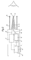
- Figure 1 is a schematic view illustrating the principal components of one form of the apparatus.
- FIG. 1 there is a body member 1 sized so as to be capable of being hand held.
- a conical receiving member 2 that tapers to an end 3.
- a tube 4 Centrally positioned in the end 3 of the member 2 is the outlet of a tube 4, circular in cross-section, that extends centrally through the conical member 2, through the body member 1 and has an inlet 5 in another wall of said member 1.
- the tube 4 is of substantially uniform cross-section and has a 90° bend therein at region 6.
- a piston 7 sized so as to form a friction fit.
- the piston 7 operates against a spring 8.
- damping means 9 in the form of a viscous liquid slug.
- a field adjusting electrode Disposed about 2 cm distance from the end 3 of the conical member 2 is a field adjusting electrode in the form of a ring 10. This ring 10 is spaced from the body member 1 by means of a cylindrical collar 11.
- the body member 1 contains therein a battery powered high voltage generator 12 that is connected by electrical switching means (not shown) to the piston 7. From the generator 12 extends a lead 13 that is embedded in the conical receiving member 2 and exits therefrom in the region of the end 3, to provide a protruding portion 14.
- a demountable hollow spray nozzle 15 of generally conical shape.
- the nozzle 15 is sufficiently resilient to be able to form a friction-fit on to the extended surface of the conical receiving member 2.
- an annular flange 16 is provided on said nozzle.
- the hollow centre of the nozzle is of conical configuration and there is a small aperture 17 at the tip of said nozzle.
- the aperture 17 is sufficiently sized so that formulation is held within the nozzle by surface tension and other effects.
- a metered dose of a formulation 18 is provided within the demountable nozzle 15.
- the piston 7 In use the piston 7 is depressed against the spring 8. This causes a current of air to move through the tube 4, the slug 9 acting as a damping control on the passage of air. The current of air passes into the hollow spray nozzle 15 and urges the formulation 18 through the aperture 17 of the tip of said nozzle in the direction of a target eye. At the same time the piston 7 activates the high voltage generator (by means not shown) which in turn causes a high voltage of the order of 16 kV to pass through lead 13 which in portion 14 thereof is in contact with the formulation 18. Thus the formulation 18 is raised to a high potential.
- the ring field adjusting electrode 10 is at earth potential.
- a body member 30 sized so as to be capable of being hand held.
- a conical nozzle 31 that tapers to an end 32.
- a tube 33 Centrally positioned in the end 32 of the nozzle 31 is the outlet of a tube 33, of uniform, circular cross section, that extends centrally through the conical nozzle 31 to a syringe, 34 forming part of a syringe pump 40 accommodated within the body member 30.
- a field adjusting electrode Disposed about 2 cm distant from the end 32 of the conical nozzle 31 is a field adjusting electrode in the form of a ring 35, spaced from the body member 30 by a cylindrical collar 36.
- the body member 30 additionally accommodates a battery powdered high voltage generator 37, from which extends a lead 38 that is embedded in the conical nozzle 31, and exits therefrom into the tube 33 near its end 32 to provide a protruding portion 39.
- the lead 38 can be adapted to make contact with the liquid being dispensed at any point of the syringe 34 or the tube 33.
- the syringe-pump 40 of the type supplied by Muirhead Vactric Components Ltd. of Beckenham, Kent, for adminstering successive doses of insulin from a reservoir syringe, comprises a mini-pump 41 which drives the plunger 42 of a replaceable syring 34, to dispense an accurately metered amount of the syringe contents through the outlet 32 of the conical nozzle 31 whenever the syringe pump 40 is activated, by activating means, shown here as a press button, 43.
- the syringe 34 contains a formulation of an ophthalmically active substance according to the invention.
- Operation of the activating means 43 causes an accurately metered quantity of the formulation, of the order of 5 ⁇ l, to pass out through the end 32 of the conical nozzle 31.
- the operation of the actuating means 43 switches on the high voltage generator 37 to supply a high voltage via the lead 38 to the protruding portion thereof 39, thus applying a high electrical potential to the formulation being discharged from the end 39 of the conical nozzle 31.
- Ephedrine (350 pg) was formulated as a 10% solution (3.5 pl) in a mixture of dimethyl isosorbide:water (9:1) which also contained hydroxypropyl cellulose (4% wt/wt).
- This formulation was sprayed, from the apparatus described hereinbefore in the specific embodiment, on to one eye of each of six male New Zealand white rabbits. The other eye remained untreated to act as a control allowing compensation for changing environmental factors to be included in the calculation of the results.
- Mydriasis resulting from the topical application of the formulation to the eye was recorded on photographic film using a camera and optical system as depicted in Figure 2.
- the pupil diameters were measured from the projected images of the processed film using engineer's calipers.
- the mydriatic response of the treated eye to ephedrine was calculated as follows: increase in pupil diameter at time(t).
- Example 2 The experimental procedure described in Example 1 was repeated, but administering to the eye 3.5 ⁇ l of a 4% w/w solution of pilocarpine in dimethylisosorbide:water (95:5 w/w) containing 3% of hydroxypropyl cellulose as a viscolizer, and measuring the miotic effect produced.
- the miotic response of the treated eye to pilocarpine at each time point was calculated as follows:- % decrease in pupil diameter at time where To and C o are the pretreatment pupil diameters of the test and control eyes respectively, and T, and C, are the pupil diameters of the test and control eyes respectively at time t.
Landscapes
- Health & Medical Sciences (AREA)
- Veterinary Medicine (AREA)
- Biomedical Technology (AREA)
- Heart & Thoracic Surgery (AREA)
- Vascular Medicine (AREA)
- Life Sciences & Earth Sciences (AREA)
- Animal Behavior & Ethology (AREA)
- General Health & Medical Sciences (AREA)
- Public Health (AREA)
- Ophthalmology & Optometry (AREA)
- Engineering & Computer Science (AREA)
- Medicinal Preparation (AREA)
- Pharmaceuticals Containing Other Organic And Inorganic Compounds (AREA)
- Medical Preparation Storing Or Oral Administration Devices (AREA)
- Materials For Medical Uses (AREA)
- Acyclic And Carbocyclic Compounds In Medicinal Compositions (AREA)
- Laser Surgery Devices (AREA)
- Electrostatic Spraying Apparatus (AREA)
- Devices For Medical Bathing And Washing (AREA)
- Media Introduction/Drainage Providing Device (AREA)
- Bidet-Like Cleaning Device And Other Flush Toilet Accessories (AREA)
- Agricultural Chemicals And Associated Chemicals (AREA)
Claims (18)
Priority Applications (1)
| Application Number | Priority Date | Filing Date | Title |
|---|---|---|---|
| AT86308677T ATE55890T1 (de) | 1985-11-13 | 1986-11-06 | Augenbehandlung. |
Applications Claiming Priority (2)
| Application Number | Priority Date | Filing Date | Title |
|---|---|---|---|
| GB858528032A GB8528032D0 (en) | 1985-11-13 | 1985-11-13 | Ocular treatment |
| GB8528032 | 1985-11-13 |
Publications (2)
| Publication Number | Publication Date |
|---|---|
| EP0224352A1 EP0224352A1 (de) | 1987-06-03 |
| EP0224352B1 true EP0224352B1 (de) | 1990-08-29 |
Family
ID=10588186
Family Applications (1)
| Application Number | Title | Priority Date | Filing Date |
|---|---|---|---|
| EP86308677A Expired - Lifetime EP0224352B1 (de) | 1985-11-13 | 1986-11-06 | Augenbehandlung |
Country Status (13)
| Country | Link |
|---|---|
| US (1) | US4952212A (de) |
| EP (1) | EP0224352B1 (de) |
| JP (1) | JP2541527B2 (de) |
| AT (1) | ATE55890T1 (de) |
| AU (1) | AU600684B2 (de) |
| CA (1) | CA1296629C (de) |
| DE (1) | DE3673769D1 (de) |
| DK (1) | DK165161C (de) |
| FI (1) | FI85558C (de) |
| GB (1) | GB8528032D0 (de) |
| NO (1) | NO172476C (de) |
| NZ (1) | NZ218269A (de) |
| ZA (1) | ZA868222B (de) |
Cited By (7)
| Publication number | Priority date | Publication date | Assignee | Title |
|---|---|---|---|---|
| US7297211B2 (en) | 2003-05-09 | 2007-11-20 | Mystic Tan, Inc. | Single-dose spray system for application of liquids onto the human body |
| US7462242B2 (en) | 2004-06-21 | 2008-12-09 | Mystic Tan, Inc. | Misting apparatus for electrostatic application of coating materials to body surfaces |
| US7913938B2 (en) | 2004-11-12 | 2011-03-29 | Mystic Tan, Inc. | Electrostatic spray nozzle with adjustable fluid tip and interchangeable components |
| US7992517B2 (en) | 2003-05-09 | 2011-08-09 | Mt Industries, Inc. | Gantry tower spraying system with cartridge/receptacle assembly |
| US11839487B2 (en) | 2010-07-15 | 2023-12-12 | Eyenovia, Inc. | Ophthalmic drug delivery |
| US11938056B2 (en) | 2017-06-10 | 2024-03-26 | Eyenovia, Inc. | Methods and devices for handling a fluid and delivering the fluid to the eye |
| US12161585B2 (en) | 2019-12-11 | 2024-12-10 | Eyenovia, Inc. | Systems and devices for delivering fluids to the eye and methods of use |
Families Citing this family (66)
| Publication number | Priority date | Publication date | Assignee | Title |
|---|---|---|---|---|
| KR920003601B1 (ko) * | 1987-09-03 | 1992-05-04 | 유니버시티 어브 죠지아 리서취 화운데이션 인코포레이티드 | 점안 싸이클로스포린(cyclosporin)의 조성물 |
| US5115971A (en) * | 1988-09-23 | 1992-05-26 | Battelle Memorial Institute | Nebulizer device |
| US5139491A (en) * | 1990-12-06 | 1992-08-18 | Allergan, Inc. | 2-decarboxyl-2-alkoxyalkyl prostaglandins as ocular hypotensives |
| GB9115275D0 (en) * | 1991-07-15 | 1991-08-28 | Unilever Plc | Colour cosmetic spray system |
| GB9115279D0 (en) * | 1991-07-15 | 1991-08-28 | Unilever Plc | Hair and scalp treatment system |
| GB9115277D0 (en) * | 1991-07-15 | 1991-08-28 | Unilever Plc | Spraying system |
| GB9115276D0 (en) * | 1991-07-15 | 1991-08-28 | Unilever Plc | Skin treatment system |
| GB9115278D0 (en) * | 1991-07-15 | 1991-08-28 | Unilever Plc | Liquid spraying apparatus and method |
| US5368582A (en) * | 1992-08-10 | 1994-11-29 | The Schepens Eye Research Institute | Method and apparatus for introducing fluid material into an eye |
| GB9224191D0 (en) * | 1992-11-18 | 1993-01-06 | Unilever Plc | Cosmetic delivery system |
| GB9405952D0 (en) * | 1994-03-25 | 1994-05-11 | Zeneca Ltd | Aqueous ophthalmic sprays |
| WO1996000050A1 (en) * | 1994-06-23 | 1996-01-04 | R.P. Scherer Corporation | Ocular treatment device |
| GB9417399D0 (en) | 1994-08-30 | 1994-10-19 | Scherer Corp R P | Ocular treatment device |
| GB9511514D0 (en) * | 1995-06-07 | 1995-08-02 | Ici Plc | Electrostatic spraying |
| CA2218879A1 (en) * | 1995-05-12 | 1996-11-14 | Genentech, Inc. | Coarse spray delivery of functional biologic materials |
| AU1201297A (en) * | 1995-12-21 | 1997-07-17 | Pharmacia & Upjohn Ab | Ophthalmic treatment |
| US6079634A (en) * | 1996-05-30 | 2000-06-27 | The Procter & Gamble Company | Electrostatic spraying |
| GB9622623D0 (en) | 1996-10-30 | 1997-01-08 | Ici Plc | Dispensing devices |
| US5807357A (en) * | 1997-08-19 | 1998-09-15 | Kang; Meng-Che | Compact nebulizer for treating the eyes |
| GB2334461B (en) | 1998-02-20 | 2002-01-23 | Bespak Plc | Inhalation apparatus |
| US6730066B1 (en) * | 1999-08-03 | 2004-05-04 | Pharmacia Ab | Liquid delivery container |
| US6739518B1 (en) * | 1999-12-21 | 2004-05-25 | E. I. Du Pont De Nemours And Company | Spray applicator |
| US6758837B2 (en) | 2001-02-08 | 2004-07-06 | Pharmacia Ab | Liquid delivery device and method of use thereof |
| BR0208303A (pt) * | 2001-03-22 | 2004-03-09 | Battelle Memorial Institute | Formações liquidas para pulverização eletroidrodin mica contendo polìmero e partìculas suspensas |
| US20040131673A1 (en) * | 2001-03-22 | 2004-07-08 | Coffee Ronald Alan | Manufacturing dissolvable dosage forms |
| GB0111721D0 (en) * | 2001-05-14 | 2001-07-04 | Electrosols Ltd | Compositions |
| US6620405B2 (en) * | 2001-11-01 | 2003-09-16 | 3M Innovative Properties Company | Delivery of hydrogel compositions as a fine mist |
| MXPA05002669A (es) * | 2002-09-13 | 2005-08-19 | Ocular Sciences Inc | Dispositivos y metodos para mejorar la vision. |
| US20050261641A1 (en) * | 2002-09-26 | 2005-11-24 | Warchol Mark P | Method for ophthalmic administration of medicament |
| US20070211212A1 (en) * | 2002-09-26 | 2007-09-13 | Percy Bennwik | Eye state sensor |
| US20100222752A1 (en) * | 2003-05-20 | 2010-09-02 | Collins Jr James F | Ophthalmic fluid delivery system |
| US8545463B2 (en) | 2003-05-20 | 2013-10-01 | Optimyst Systems Inc. | Ophthalmic fluid reservoir assembly for use with an ophthalmic fluid delivery device |
| ATE501766T1 (de) * | 2003-05-20 | 2011-04-15 | James F Collins | Ophthalmisches arzneimittelabgabesystem |
| CA2563365A1 (en) * | 2004-04-23 | 2005-11-03 | Mystic Pharmaceuticals, Inc. | Multiple unit dose drug delivery system |
| EP1771131A2 (de) | 2004-05-20 | 2007-04-11 | CooperVision Inc. | Hornhaut-onlays und wellenfrontaberrationskorrektion zur verbesserung des visus |
| US20070048338A1 (en) * | 2005-08-26 | 2007-03-01 | Ladd Byron S | Compositions and methods for surface treatment in medical and surgical procedures |
| WO2007083164A2 (en) * | 2006-01-17 | 2007-07-26 | Aerstream Technology Limited | Liquid electrostatic spray composition |
| US7883520B2 (en) | 2006-04-10 | 2011-02-08 | Forsight Labs, Llc | Corneal epithelial pocket formation systems, components and methods |
| WO2008086413A2 (en) | 2007-01-09 | 2008-07-17 | Mystic Pharmaceuticals, Inc. | Intranasal cartridge devices |
| WO2008129866A1 (ja) * | 2007-04-12 | 2008-10-30 | Daikin Industries, Ltd. | 噴霧装置 |
| JP2008279243A (ja) * | 2007-04-12 | 2008-11-20 | Daikin Ind Ltd | 噴霧装置 |
| JP2008264728A (ja) * | 2007-04-24 | 2008-11-06 | Daikin Ind Ltd | 静電噴霧装置 |
| US8683995B2 (en) | 2007-05-16 | 2014-04-01 | Mystic Pharmaceuticals, Inc. | Dose dispensing containers |
| EP2164799B1 (de) * | 2007-05-16 | 2018-12-26 | Mystic Pharmaceuticals, Inc. | Kombinationsdosiereinheitabgabebehälter |
| US9248076B2 (en) | 2007-05-16 | 2016-02-02 | Mystic Pharmaceuticals, Inc. | Dose dispensing containers |
| CA2699634C (en) | 2007-09-14 | 2015-06-09 | Mystic Pharmaceuticals, Inc. | Deep draw container forming method |
| US20110014294A1 (en) * | 2008-03-03 | 2011-01-20 | Pharmalight Inc. | Stimulation of ocular retrobulbar blood flow using ocular irritants |
| JP5178309B2 (ja) * | 2008-05-09 | 2013-04-10 | オリンパス株式会社 | 薬液投与装置 |
| JP5470890B2 (ja) * | 2009-02-13 | 2014-04-16 | ダイキン工業株式会社 | 設置式の静電噴霧装置 |
| US8299079B2 (en) | 2009-05-22 | 2012-10-30 | Kaufman Herbert E | Preparations and methods for ameliorating or reducing presbyopia |
| WO2010135731A1 (en) * | 2009-05-22 | 2010-11-25 | Kaufman Herbert E | Preparations and methods for ameliorating or reducing presbyopia |
| US9039666B2 (en) | 2009-10-21 | 2015-05-26 | Johnson & Johnson Vision Care, Inc. | Method and apparatus for liquid dispensing |
| US20110106025A1 (en) * | 2009-10-29 | 2011-05-05 | Hall Gary S | Ophthalmic fluid pump |
| US20110189356A1 (en) * | 2010-01-29 | 2011-08-04 | Shy Brothers Farm | Methods of Storing Cheese |
| EP2593056B1 (de) | 2010-07-15 | 2020-10-21 | Eyenovia, Inc. | Vorrichtung zur tropfenerzeugung |
| WO2012009696A2 (en) | 2010-07-15 | 2012-01-19 | Corinthian Ophthalmic, Inc. | Ophthalmic drug delivery |
| JP2013531548A (ja) | 2010-07-15 | 2013-08-08 | コリンシアン オフサルミック,インコーポレイティド | 遠隔治療及び遠隔モニタリングを実施する方法及びシステム |
| JP5876246B2 (ja) | 2010-08-06 | 2016-03-02 | 住友化学株式会社 | 活性成分を空気中に送達するための組成物およびその利用 |
| AU2011265562A1 (en) | 2011-01-12 | 2012-07-26 | Sumitomo Chemical Company, Limited | Method of controlling harmful arthropod, composition, and electrostatic spray device |
| US20130172830A1 (en) | 2011-12-12 | 2013-07-04 | Corinthian Ophthalmic, Inc. | Ejector mechanism, ejector device, and methods of use |
| JP6329130B2 (ja) | 2012-04-10 | 2018-05-30 | アイノビア,インコーポレイティド | 噴霧エジェクタ機構、電荷分離及び制御可能な液滴電荷を提供する装置、並びに低投与量の点眼 |
| EP2838669B1 (de) | 2012-04-20 | 2018-01-03 | Eyenovia, Inc. | Sprühausstossvorrichtung und verwendungsmethode |
| EA201492094A1 (ru) | 2012-05-15 | 2015-04-30 | Айновиа, Инк. | Эжекторные устройства, способы, возбудители и схемы для них |
| US10413359B2 (en) * | 2013-07-18 | 2019-09-17 | International Business Machines Corporation | Laser-assisted transdermal delivery of nanoparticulates and hydrogels |
| CN111150637B (zh) * | 2020-01-03 | 2022-05-20 | 王莹 | 一种便携式洗眼喷雾器 |
| NL2025366B1 (en) * | 2020-04-17 | 2021-10-26 | Gilbert Tech Bv | Electronic inhaler and method for adjusting the same |
Family Cites Families (7)
| Publication number | Priority date | Publication date | Assignee | Title |
|---|---|---|---|---|
| US3934585A (en) * | 1970-08-13 | 1976-01-27 | Maurice David M | Method and apparatus for application of eye drops |
| US4067499A (en) * | 1976-02-17 | 1978-01-10 | Cohen Milton J | Non-aerosol continuous spray dispenser |
| IE45426B1 (en) * | 1976-07-15 | 1982-08-25 | Ici Ltd | Atomisation of liquids |
| GB1569707A (en) * | 1976-07-15 | 1980-06-18 | Ici Ltd | Atomisation of liquids |
| US4390542A (en) * | 1980-12-02 | 1983-06-28 | Schachar Ronald A | Method for inhibiting contraction of opthalmic wounds or incisions |
| US4564016A (en) * | 1982-05-24 | 1986-01-14 | The Board Of Trustees Of The Leland Stanford Junior University | Apparatus for introducing ionized drugs into the posterior segment of the eye and method |
| US4544570A (en) * | 1984-01-26 | 1985-10-01 | Nordson Corporation | Electrostatic high voltage isolation system with internal charge generation |
-
1985
- 1985-11-13 GB GB858528032A patent/GB8528032D0/en active Pending
-
1986
- 1986-10-28 ZA ZA868222A patent/ZA868222B/xx unknown
- 1986-10-30 AU AU64534/86A patent/AU600684B2/en not_active Expired
- 1986-10-30 NO NO864339A patent/NO172476C/no unknown
- 1986-11-06 DE DE8686308677T patent/DE3673769D1/de not_active Expired - Lifetime
- 1986-11-06 EP EP86308677A patent/EP0224352B1/de not_active Expired - Lifetime
- 1986-11-06 AT AT86308677T patent/ATE55890T1/de not_active IP Right Cessation
- 1986-11-11 DK DK538786A patent/DK165161C/da not_active IP Right Cessation
- 1986-11-12 NZ NZ218269A patent/NZ218269A/xx unknown
- 1986-11-12 CA CA000522660A patent/CA1296629C/en not_active Expired - Lifetime
- 1986-11-13 FI FI864621A patent/FI85558C/fi not_active IP Right Cessation
- 1986-11-13 JP JP61268791A patent/JP2541527B2/ja not_active Expired - Lifetime
-
1989
- 1989-01-23 US US07/299,689 patent/US4952212A/en not_active Expired - Lifetime
Cited By (10)
| Publication number | Priority date | Publication date | Assignee | Title |
|---|---|---|---|---|
| US7297211B2 (en) | 2003-05-09 | 2007-11-20 | Mystic Tan, Inc. | Single-dose spray system for application of liquids onto the human body |
| US7387684B2 (en) | 2003-05-09 | 2008-06-17 | Mystic Tan, Inc. | Single-dose spray system for application of liquids onto the human body |
| US7992517B2 (en) | 2003-05-09 | 2011-08-09 | Mt Industries, Inc. | Gantry tower spraying system with cartridge/receptacle assembly |
| US7462242B2 (en) | 2004-06-21 | 2008-12-09 | Mystic Tan, Inc. | Misting apparatus for electrostatic application of coating materials to body surfaces |
| US7913938B2 (en) | 2004-11-12 | 2011-03-29 | Mystic Tan, Inc. | Electrostatic spray nozzle with adjustable fluid tip and interchangeable components |
| US11839487B2 (en) | 2010-07-15 | 2023-12-12 | Eyenovia, Inc. | Ophthalmic drug delivery |
| US12490932B2 (en) | 2010-07-15 | 2025-12-09 | Eyenovia, Inc. | Ophthalmic drug delivery |
| US11938056B2 (en) | 2017-06-10 | 2024-03-26 | Eyenovia, Inc. | Methods and devices for handling a fluid and delivering the fluid to the eye |
| US12213912B2 (en) | 2017-06-10 | 2025-02-04 | Eyenovia, Inc. | Methods and devices for handling a fluid and delivering the fluid to the eye |
| US12161585B2 (en) | 2019-12-11 | 2024-12-10 | Eyenovia, Inc. | Systems and devices for delivering fluids to the eye and methods of use |
Also Published As
| Publication number | Publication date |
|---|---|
| FI85558B (fi) | 1992-01-31 |
| DK165161C (da) | 1993-03-01 |
| NZ218269A (en) | 1989-11-28 |
| US4952212A (en) | 1990-08-28 |
| FI864621A7 (fi) | 1987-05-14 |
| NO172476B (no) | 1993-04-19 |
| JPS62142110A (ja) | 1987-06-25 |
| ZA868222B (en) | 1987-07-29 |
| DK538786A (da) | 1987-05-14 |
| CA1296629C (en) | 1992-03-03 |
| NO864339D0 (no) | 1986-10-30 |
| DK165161B (da) | 1992-10-19 |
| FI85558C (fi) | 1992-05-11 |
| JP2541527B2 (ja) | 1996-10-09 |
| NO864339L (no) | 1987-05-14 |
| EP0224352A1 (de) | 1987-06-03 |
| FI864621A0 (fi) | 1986-11-13 |
| GB8528032D0 (en) | 1985-12-18 |
| AU600684B2 (en) | 1990-08-23 |
| AU6453486A (en) | 1987-05-21 |
| ATE55890T1 (de) | 1990-09-15 |
| DK538786D0 (da) | 1986-11-11 |
| DE3673769D1 (de) | 1990-10-04 |
| NO172476C (no) | 1993-07-28 |
Similar Documents
| Publication | Publication Date | Title |
|---|---|---|
| EP0224352B1 (de) | Augenbehandlung | |
| US5053000A (en) | Ocular treatment | |
| EP0678337B1 (de) | Vorrichtung | |
| AU594429B2 (en) | Apparatus for producing a spray of droplets of a liquid | |
| HK1044126A1 (zh) | 鼻吸器 | |
| JP2004533304A (ja) | 液体を目に塗布する噴霧器 | |
| US7931020B2 (en) | Dissociated discharge EHD sprayer with electric field shield | |
| US20110174304A1 (en) | Electrohydrodynamic aerosolization device having a time varying voltage | |
| AU3269699A (en) | Nasal spray device with improved spray geometry | |
| US20150031543A1 (en) | Compositions for aerosolization of highly conductive solutions | |
| US7891578B2 (en) | Liquid formations for electrohydrodymanic spraying containing polymer and suspended particles | |
| CA2182694C (en) | Aqueous ophthalmic sprays | |
| NO301524B1 (no) | Fremgangsmåte ved dannelse av en elektrisk ladet spray omfattende en oftalmisk aktiv substans og et apparat for utförelse av fremgangsmåten | |
| US20030185762A1 (en) | Highly aqueous liquid carrier formulations |
Legal Events
| Date | Code | Title | Description |
|---|---|---|---|
| PUAI | Public reference made under article 153(3) epc to a published international application that has entered the european phase |
Free format text: ORIGINAL CODE: 0009012 |
|
| AK | Designated contracting states |
Kind code of ref document: A1 Designated state(s): AT BE CH DE FR GB IT LI LU NL SE |
|
| 17P | Request for examination filed |
Effective date: 19870928 |
|
| 17Q | First examination report despatched |
Effective date: 19890522 |
|
| GRAA | (expected) grant |
Free format text: ORIGINAL CODE: 0009210 |
|
| AK | Designated contracting states |
Kind code of ref document: B1 Designated state(s): AT BE CH DE FR GB IT LI LU NL SE |
|
| ITF | It: translation for a ep patent filed | ||
| REF | Corresponds to: |
Ref document number: 55890 Country of ref document: AT Date of ref document: 19900915 Kind code of ref document: T |
|
| REF | Corresponds to: |
Ref document number: 3673769 Country of ref document: DE Date of ref document: 19901004 |
|
| ET | Fr: translation filed | ||
| PLBE | No opposition filed within time limit |
Free format text: ORIGINAL CODE: 0009261 |
|
| STAA | Information on the status of an ep patent application or granted ep patent |
Free format text: STATUS: NO OPPOSITION FILED WITHIN TIME LIMIT |
|
| 26N | No opposition filed | ||
| ITTA | It: last paid annual fee | ||
| REG | Reference to a national code |
Ref country code: GB Ref legal event code: 732E |
|
| EPTA | Lu: last paid annual fee | ||
| EAL | Se: european patent in force in sweden |
Ref document number: 86308677.3 |
|
| REG | Reference to a national code |
Ref country code: GB Ref legal event code: 732E |
|
| REG | Reference to a national code |
Ref country code: GB Ref legal event code: IF02 |
|
| PGFP | Annual fee paid to national office [announced via postgrant information from national office to epo] |
Ref country code: LU Payment date: 20050926 Year of fee payment: 20 |
|
| PGFP | Annual fee paid to national office [announced via postgrant information from national office to epo] |
Ref country code: AT Payment date: 20051004 Year of fee payment: 20 Ref country code: GB Payment date: 20051004 Year of fee payment: 20 |
|
| PGFP | Annual fee paid to national office [announced via postgrant information from national office to epo] |
Ref country code: NL Payment date: 20051005 Year of fee payment: 20 |
|
| PGFP | Annual fee paid to national office [announced via postgrant information from national office to epo] |
Ref country code: FR Payment date: 20051104 Year of fee payment: 20 |
|
| PGFP | Annual fee paid to national office [announced via postgrant information from national office to epo] |
Ref country code: SE Payment date: 20051107 Year of fee payment: 20 |
|
| PGFP | Annual fee paid to national office [announced via postgrant information from national office to epo] |
Ref country code: IT Payment date: 20051116 Year of fee payment: 20 |
|
| PGFP | Annual fee paid to national office [announced via postgrant information from national office to epo] |
Ref country code: DE Payment date: 20051130 Year of fee payment: 20 |
|
| PGFP | Annual fee paid to national office [announced via postgrant information from national office to epo] |
Ref country code: BE Payment date: 20051207 Year of fee payment: 20 |
|
| PGFP | Annual fee paid to national office [announced via postgrant information from national office to epo] |
Ref country code: CH Payment date: 20051216 Year of fee payment: 20 |
|
| PG25 | Lapsed in a contracting state [announced via postgrant information from national office to epo] |
Ref country code: GB Free format text: LAPSE BECAUSE OF EXPIRATION OF PROTECTION Effective date: 20061105 |
|
| PG25 | Lapsed in a contracting state [announced via postgrant information from national office to epo] |
Ref country code: NL Free format text: LAPSE BECAUSE OF EXPIRATION OF PROTECTION Effective date: 20061106 |
|
| REG | Reference to a national code |
Ref country code: GB Ref legal event code: PE20 |
|
| REG | Reference to a national code |
Ref country code: CH Ref legal event code: PL |
|
| NLV7 | Nl: ceased due to reaching the maximum lifetime of a patent |
Effective date: 20061106 |
|
| EUG | Se: european patent has lapsed | ||
| BE20 | Be: patent expired |
Owner name: *IMPERIAL CHEMICAL INDUSTRIES P.L.C. Effective date: 20061106 |