EP0223384A1 - Fahrzeuglastüberwachungssystem - Google Patents
Fahrzeuglastüberwachungssystem Download PDFInfo
- Publication number
- EP0223384A1 EP0223384A1 EP86307712A EP86307712A EP0223384A1 EP 0223384 A1 EP0223384 A1 EP 0223384A1 EP 86307712 A EP86307712 A EP 86307712A EP 86307712 A EP86307712 A EP 86307712A EP 0223384 A1 EP0223384 A1 EP 0223384A1
- Authority
- EP
- European Patent Office
- Prior art keywords
- load
- vehicle
- inclination
- carrier
- tipping
- Prior art date
- Legal status (The legal status is an assumption and is not a legal conclusion. Google has not performed a legal analysis and makes no representation as to the accuracy of the status listed.)
- Granted
Links
- 238000012544 monitoring process Methods 0.000 title claims abstract description 15
- 230000005484 gravity Effects 0.000 claims abstract description 25
- 238000000034 method Methods 0.000 claims description 14
- 230000008569 process Effects 0.000 claims description 9
- 230000000007 visual effect Effects 0.000 claims description 9
- 230000004044 response Effects 0.000 claims description 3
- 230000000712 assembly Effects 0.000 claims description 2
- 238000000429 assembly Methods 0.000 claims description 2
- 230000002401 inhibitory effect Effects 0.000 claims 1
- 239000000306 component Substances 0.000 description 26
- 239000000446 fuel Substances 0.000 description 14
- 238000009826 distribution Methods 0.000 description 9
- 230000006870 function Effects 0.000 description 9
- 238000005259 measurement Methods 0.000 description 7
- 230000000694 effects Effects 0.000 description 6
- 230000008859 change Effects 0.000 description 5
- 239000002828 fuel tank Substances 0.000 description 5
- 230000009471 action Effects 0.000 description 4
- 230000007246 mechanism Effects 0.000 description 3
- 238000001514 detection method Methods 0.000 description 2
- 238000010586 diagram Methods 0.000 description 2
- 239000012530 fluid Substances 0.000 description 2
- 239000000463 material Substances 0.000 description 2
- 230000002265 prevention Effects 0.000 description 2
- 238000012545 processing Methods 0.000 description 2
- 230000003321 amplification Effects 0.000 description 1
- 230000001419 dependent effect Effects 0.000 description 1
- 238000013461 design Methods 0.000 description 1
- 238000003199 nucleic acid amplification method Methods 0.000 description 1
- 238000005303 weighing Methods 0.000 description 1
- 238000003466 welding Methods 0.000 description 1
Images


Classifications
-
- G—PHYSICS
- G01—MEASURING; TESTING
- G01G—WEIGHING
- G01G19/00—Weighing apparatus or methods adapted for special purposes not provided for in the preceding groups
- G01G19/08—Weighing apparatus or methods adapted for special purposes not provided for in the preceding groups for incorporation in vehicles
- G01G19/12—Weighing apparatus or methods adapted for special purposes not provided for in the preceding groups for incorporation in vehicles having electrical weight-sensitive devices
-
- B—PERFORMING OPERATIONS; TRANSPORTING
- B60—VEHICLES IN GENERAL
- B60P—VEHICLES ADAPTED FOR LOAD TRANSPORTATION OR TO TRANSPORT, TO CARRY, OR TO COMPRISE SPECIAL LOADS OR OBJECTS
- B60P1/00—Vehicles predominantly for transporting loads and modified to facilitate loading, consolidating the load, or unloading
- B60P1/04—Vehicles predominantly for transporting loads and modified to facilitate loading, consolidating the load, or unloading with a tipping movement of load-transporting element
- B60P1/045—Levelling or stabilising systems for tippers
Definitions
- This invention relates to a vehicle load monitoring system for a road vehicle having a tipping load carrier.
- the present invention seeks to reduce the susceptibility of load measurement using an on-board system in a load tipping vehicle to variation in the vehicle's inclination during measurement.
- the present invention provides a load monitoring system for a road vehicle with a tipping load carrier, comprising load sensor means for mounting on the vehicle for sensing a plurality of weight components of the load carrier at longitudinally spaced positions thereof, inclination sensing means for mounting on the vehicle for providing a sensor output indicative of the inclination of the load carrier to a datum, e.g. the horizontal, a computing apparatus which is operable to process the sensor outputs from said load and inclination sensor means to provide at least one computer output indicative of the value of a required load parameter, resolved to the datum position of the vehicle, and visual display means for producing a visual representation of the computer output.
- load sensor means for mounting on the vehicle for sensing a plurality of weight components of the load carrier at longitudinally spaced positions thereof
- inclination sensing means for mounting on the vehicle for providing a sensor output indicative of the inclination of the load carrier to a datum, e.g. the horizontal
- a computing apparatus which is operable to process the sensor outputs from said load and
- the load sensor means preferably comprises a forward sensor for sensing the hydraulic pressure in a forward carrier-lifting ram mounted on the mid-line of the vehicle chassis and a pair of rear load sensors mounted at opposite sides of the carrier of parts of the vehicle chassis affected in a predetermined manner by the load applied to the chassis by the weight of the carrier.
- These rear load sensors are preferably shear pins in two pivot assemblies by which the rear end of the carrier is pivoted to the chassis.
- the computing apparatus is preferably programmed to calculate from the resolved outputs of the load sensor means the magnitude of a load on the carrier and the position of its centre of gravity, and to further calculate, in accordance with predetermined vehicle parameters, those components of axle weights of the loaded vehicle which are due to said load.
- the system may be operable to execute a load measuring operation after a predetermined degree of tipping of the carrier; only then is the hydraulic pressure in the ram representative of the respective weight component.
- the inclination sensing means may be mounted on the vehicle chassis or on the load carrier.
- the inclination of the carrier will be known as the measurement operation is carried out at a known angle of tip of the carrier relative to the chassis.
- the carrier inclination is given directly by the sensor output.
- the present invention seeks to avoid the occurence of situations of load and/or vehicle instability during unloading.
- the present invention provides a load monitoring system for a road vehicle with a tipping load carrier, comprising load sensor means for mounting on the vehicle for sensing a plurality of weight components of the carrier at spaced positions thereon, inclination sensor means for mounting on the vehicle, computing apparatus which is operable to process the sensor outputs from the load and inclination sensor means before and/or during tipping of the carrier for unloading, so as to determine or predict the occurrence during the unloading of a condition of vehicle instability.
- the load sensor arrangement is prefereably as in the previous aspect.
- a potential problem of instability can be determined, for example, using an inclinometer mounted so as to detect lateral inclination and a sensor arrangement which detects the magnitude of the load and lateral position of its centre of gravity before tipping commences.
- the computer can be programmed to predict from this data the liklihood of instability occurring and can energise a visual and/or audible warning device and optionally activate a tipping prevention device.
- Another potential problem can be determined using additionally an inclinometer on the load carrier for detecting the tipping angel.
- a sudden lateral shift of the load's centre of gravity for example due to the sudden downward movement of load material on one side of the carrier but not the other, can present a serious danger where the vehicle has significant lateral inclination.
- the computing apparatus may be programmed to detect such a situation and preferably to control a tipping mechanism immediately and quickly to reduce the tipping angle.
- these two functions are combined with a function of continuous monitoring during tipping, this being performed using outputs from three inclinometers, namely longitudinal inclinometers on the chassis and the tipping body and a lateral inclinometer on the chassis.
- the computing apparatus is operable continuously during unloading to predict the locus of the load's centre of gravity and to determine if such locus is acceptable.
- the provision of two longitudinal inclinometers permits detection of the carrier inclination with respect both to the chassis and to the horizontal. Thus even when the vehicle is parked on an incline, the exact stage of tipping is always known without the need to memorize inclination data before the commencement of tipping.
- the computing apparatus is preferably operable also to receive a fuel sensor output representing the current fuel level within the vehicle's fuel tank or tanks. During unloading this information can be used to determine the destabilising affect on the vehicle's resultant center of gravity of the current weight of fuel carried in the off-centre fuel tank(s).
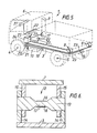
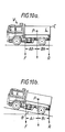
- a commercial road vehicle 1 to which a system 2 according to the present invention is applicable comprises a tipping lorry having a chassis 3 supported by front and rear wheeled axles 4 and 5 respectively, a driver's cab 6 and a load carrier 7 mounted on the chassis 3 by a pair of rear hinges 8 axially aligned transverse the longitudinal axis of the vehicle at the rear end of the chassis, a hydraulic ram 9 at the front end of the body 7, and a fuel tank 10.
- the ram 9 is actuable to lift the front end of the body 7 so as to cause it to turn about the hinges 8 for disposing of a load 11 carried by the carrier 7, as shown in fig. 9.
- the base of the carrier 7 rests on the chassis 3 between the ram 9 and the rear hinges 8, but for the performance of a weighing operation, to be described later, the ram can be actuated to lift the load carrier 7 slightly (e.g. by 1° - 2°) relative to the chassis so that the total weight of the carrier 7 and the load 11 is borne by the hydraulic ram 9 and the rear hinges 8.
- each of the rear hinges 8 includes a shear pin sensor, for example as illustrated in fig. 6. with reference to figure 6, the shear pin 12 comprises a waisted hinge pin 13 fixed in a hinge aperture of a carrier support member 14 in turn fixed to the chassis 3, pivot member 15 which is fixed to the carrier 7 being pivotally mounted on this hinge pin 13.
- the load applied to the shear pin 12 due to the weight of the load carrier 7 creates a shear strain in the hinge pin 13, and this strain is detected by at least one strain gauge 16 mounted on the top and/or bottom of the central portion 13' of the pin 13.
- a fluid pressure sensor 17 is mounted to the ram 9 to sense the hydraulic pressure therein, this pressure being indicative of that component of the weight of the carrier which is supported by the ram 9 whenever the carrier 7 is lifted from the chassis.
- a first inclinometer 18 is mounted on the chassis for detecting longitudinal (i.e. front-to-back) inclination thereof the chassis.
- a second inclinometer 19 is mounted on the chassis for detecting lateral (i.e. side-to-side) inclination there, and a third inclinometer 20 is mounted on the load carrier 7 for detecting longitudinal inclination thereof the carrier.
- An inclinometer is an instrument which can provide a sensor output indicative of the inclination of a body to which it is attached, normally with respect to the horizontal.
- a typical commercially available form of inclinometer has a casing, a pendulum member suspended within the casing, and means which provides a signal which varies in accordance with the angular relationship between the casing and the pendulum.
- a fuel sensor 21 is mounted on or in the fuel tank 10 for detecting the amount of fuel in the tank.
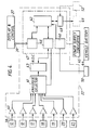
- the outputs from the shear pin sensors 12, the hydraulic sensor 17, the inclinometers 18, 19 and 20 and the fuel sensor 21 are coupled to a microprocessor control unit 22 located in the drivers cab 6, by way of individual leads 23, a junction box 24 and a common cable 25.
- the control unit 22 has an electronics board 26 carrying a microprocessor and is coupled to a display and control console 27 positioned suitably within the drivers cab for operation and viewing by the driver.
- the console 27 has a tube-shaped outercasting with apertures for a four-digit numerical display panel 28, a mode indicator 29 and four operating buttons 30, 31, 32 and 33, the functions for which will be discussed later.
- load sensor outputs indicative of the rear component of the load carrier weight could alternatively be derived from strain links 51 attached to opposite sides of the rear of the chassis at positions where the load applied through the rear hinges has a predetermined strain effect. A suitable position is between the hinges and the rear spring rear hanging brackets 34 (see fig 8).
- such a strain link comprises a pair of conventional strain gauges 16 fixed on opposite surfaces of a strain link 35 which is secured to a longitudinal load-bearing side component 36 of the chassis at a rear position mentioned above.
- the opposite ends of the strain link are securely bolted to respective ones of a pair of support feet 37, and these feet are welded at 35'to the component 36.
- feet 37 In the absence of feet 37 or where welding to a chassis component 36 is undesirable it is possible to securely bolt the link 35 directly to the chassis component.
- each gauge will be connected, in a conventional manner, in one arm of a respective bridge network.
- An adjustable component in another arm of the bridge is used for calibration.
- the provision in each embodiment of the pair of gauges is to permit compensation for the affect of temperature change etc.
- the signals from the various sensors are routed via the junction box (not shown in this figure) to the control unit 22 which has a plurality of input line 38 for receiving these sensor signals.
- a cable 39 between the control unit and the console 27 comprises a number of lines which carry control signals generated in response to the operation of the buttons 30 to 33, to the microprocessor, and a plurality of output lines from the microprocessor for controlling the display panel 28 and mode indicator 29.
- the sensor signals input to the control unit 22 are amplified in respective amplifiers 40, selected by an analogue selector 41 controlled by the microprocessor 42, and digitalised into a form suitable for use in the central processing unit of the microprocessor by an analogue-two-digital converter 43.
- the memory of the microprocessor contains instructions defining an operating program, and can temporarily store values produced by the calculating operations performed by the CPU during operation of the system.
- the microprocessor is arranged to be powered from the battery 44 of the vehicle via a suitable voltage converter 45.
- I-O units 46 receive inputs to and supply outputs from the microprocessor assembly 47.
- a serial input/output unit 48 can output information provided by the microprocessor 42 from the control unit 22, for example to a log recording device 49.
- the microprocessor 42 is programmed to process the signals from the shear pins, inclinometers and fuel gauge, and to drive the digital display 28 to indicate the value of a required load parameter to indicate to the driver the distribution of the loading during loading so as to advise him of compliance with limits for axle and gross vehicle weights.
- the processing of the sensor outputs is such as to detect or predict the occurrence of dangerous situations of vehicle instability.
- the required function of the controlled unit 22 is selected by operation of the buttons 30 to 33.
- Button 31 is labelled "weight” and can be operated to cause the calculated load parameters to be displayed during loading.
- Button 32 is a calibration button which can be operated when certain calibration functions, to be described later, are required.
- Button 33 is a "time-set” button which is operated to set the time indicated by the digital display in a clock mode of the system. It should be mentioned that the microprocessor also includes a continually running clock, and the display is so controlled that it will show time, unless the reset, weight or calibration modes are selected.
- the control system also includes a detector 50 for detecting engagement of the drive mechanism for the hydraulic ram when the driver instructs tipping for example, the sensor 50 can sense energisation of an indicating circuit which includes a lamp in the cab for displaying selection of tipping.
- the mode indicator 29 is controlled to display a character indicating the present mode of the system.
- the system When placed into the "weight" indicating mode during loading, the system automatically and repetitively runs through a cycle of load parameter display.
- this sequence is; front weight component (sensed by the sensor 17); rear weight component (sensed by the shear pins 12); total load, each parameter being identified by a given digit display by the mode indicator.
- the microprocessor 42 is preprogrammed with the threshold values for the calculated load parameters corresponding to the legal requirements applicable to the particular vehicle concerned, and responds to any given load parameter exceeding the relevant threshold by interrupting the sequence and providing a visual warning of the overload conditions.
- the warning comprises the repeated flashing of the mode display digit for the offending load parameter. When this occurs, the sequence may be resumed by a further opperation of the weight button 31.
- the "reset" button 30 allows for the resetting of the system after it has responded to the detection before or during unloading of a potentially dangerous situation of instability. The monitoring procedures for unloading will be discussed in greater detail later.
- the system provides two calibration functions which can be selected by operation of the "calibration" button 32, followed by another one of the funtion buttons.
- the first of these functions is an initialisation operation which is carried out when the system is first installed in the vehicle for the purposes of calibration of the various different sensors.
- the program in the microprocessor assumes that the outputs of the sensors will have certain predetermined values under given load and vehicle conditions, and this initialisation procedure is necessary to establish this calibration of the sensors.
- the "weight" button 25 is operated to select the different sensors in a predetermined sequence, the selected sensor being identified by the display of the mode indicator 29. For each selected sensor, a zero condition corresponding to a predetermined load or vehicle condition is established.
- Adjustments are made to set both the sensor output, and the amplified sensor output to zero in this predetermined condition.
- a predetermined non-zero condition is then applied, e.g. by placing a known load at a given position on the carrier 7, and the relevant amplification factor is adjusted to provide the require predetermined output. This procedure is repeated for each sensor in turn.
- the system can be made to perform a self-checking routine.
- the vehicle is placed under standard conditions, e.g. on level ground with no load, and the calibration button 32 is operated, followed by a predtermined sequence of the other buttons.
- the system reads the sensor outputs in a predetermined sequence and compares them with predetermined reference values stored in the microprocessor memory. If any of the measured values is beyond a predetermined tolerance with respect to the respective reference value, the sensor reading is repeatedly flashed on the numerical display 28 to give a visual warning.
- the mode indicator 29 identifies the particular sensor concerned, and the relevant sensor and/or amplifier adjustment can then be made to bring the system back into calibration.
- the microprocessor may be arranged to operate in conjunction with the distance measuring element of a tachograph 52 which is a time-distance measurement and recording device.
- the system can be operated to provide the driver with information as to his ability to continue to drive or need to take a break and the period of time in which the action must be carried out in compliance with the legal requirements of maximum driving hours in a predetermined period. This information can be retrieved in combination with the fuel and load measurements to provide a record for management purposes of time, distance, fuel, weight and unauthorised activity.
- the microprocessor is adapted to compensate both during loading and unloading for fuel weight.
- the microprocessor adds to the sum of the calculated applied load and the vehicle unladen weight a factor corresponding to the maximum weight of fuel which the vehicle can carry, when determining the value for gross vehicle weight.
- the affect of this maximum fuel weight on both (or all) axles which is known from the vehicle geometry, is added to the known effect of the unladen vehicle weight and the calculated effect of the measured load acting at the calculated position of its centre of gravity.
- the displaying load parameters will correspond to the full-tank condition of the vehicle.
- the affects on the vehicle's centre of gravity of reduced fuel contents can also be calculated and appropriate compensation made.
- the output of the shear pin and hydraulic pressure sensors for a given vehicle loading is affected significantly by the inclination of the vehicle to the horizontal.
- the legal limits for the load parameters are set for a horizontal disposition of the vehicle, but it frequently happens that loading-up of the vehicle takes place on an incline.
- the microprocessor in the embodiment of the present invention is programmed to compensate for any inclination of the vehicle to the horizontal so that the readings provided on the numerical display correspond to the values which the load parameters would assume in the horizontal position of the vehicle.
- the microprocessor is programmed in accordance with the known geometrical configuration of the vehicle and the predeterminable functions relating the vehicle inclination to the change in the effect of the load on the sensors.
- front and rear load weight components and payload could be adapted to display other combinations of critical parameters, e.g. front and rear axle weights and either payload or gross vehicle weight.
- the vehicle is placed at the loading position, which may be on horizontal or sloping ground. If the driver decides that he must monitor the loading, he will press the "weight" button, and this will initiate a preliminary operation of the hydraulic ram to lift slightly the front end of the carrier 7 of the chassis. In this condition, the whole of the weight of the carrier 7 acts on the rear shear pin sensors and, through the operating fluid of the hydraulic ram, the pressure sensor 17. The load material is then loaded progressively on to the carrier 7, and the control unit operates intermittently to sample the load outputs and calculate and display the required parameters. The front components of the combined weight of the carrier and load is given by the output of the sensor 17, and the rear weight component is given by the combined outputs of the two shear pins 12.
- the proportion of each measured component due to the load can be calculated, given that the weight and geometry of the carrier 7 are known parameters.
- the longitudinal distribution of the load is represented by the relative magnitudes of the front and rear load components, and the lateral distribution is represented by the relative magnitudes of the left and right rear weight components. Accordingly, both the magnitude of the load and the position of its center of gravity can be calculated, and the affects of the load upon the front and rear axle weights determined.
- the load measurements will automatically be corrected for any longitudinal inclination of the vehicle, as sensed by either inclinometer 18 or 20. By observing the numerical and monitor displays 28 and 29, the driver can keep a check on payload and load distribution during the loading operation, and make any required adjustments.
- the display displays cyclically front weight component, rear weight component and payload
- he will compare the displayed figures with known predetermined limits so as to ensure proper load distribution and prevention of overloading.
- the system will itself indicate when any threshold is exceeded.
- the output of a single inclinometer for longitudinal inclination sensing is sufficient.
- the vehicle is driven to the site for unloading, which may be on level ground or on an incline having one or both of longitudinal and lateral incline components.
- Operation by the driver of the tipping switch in the cab initiates a compulsory tipping safety check procedure, the first step of which involves operation of the hydraulic ram to lift the carrier 7 slightly from the chassis.
- the system computes from the load sensor outputs the magnitude of the load and the position of its center of gravity and then determines whether or not the combination of these parameters with measured values for longitudinal and/or lateral inclination, as indicated by the outputs of the inclinometers 18 and 19, is acceptable for tipping to proceed, or it it could lead to a dangerous situation at some stage during tipping. If the combination is acceptable, tipping proceeds automatically.
- the drive for the hydraulic ram is disabled and the carrier 7 is returned to the "down" position on the chassis. Also, a visual and/or audible alarm is given to the driver, advising him of the current unsafe conditions. Before re-attempting tipping at another location of the vehicle, the driver must operate the reset button so as to reset the measuring system.
- the microprocessor continually monitors the sensor outputs to detect the predict the occurrence of unsafe conditions.
- the microprocessor is preprogrammed to continually caculate from the sensor outputs the current position of the centre of gravity both of the load and of the vehicle. It can also extrapalate from the current situation up to the maximum tipping angle, and determine whether or not, if tipping continues at the current longitudinal and lateral vehicle inclinations and if the load distribution remains unchanged, a dangerous situation will occur. This determination will depend very much upon the lateral inclination of the chassis, as indicated by the output of the inclinometer 19.
- the microprocessor does determines that a dangerous situation may arise upon further tipping, the hydraulic drive is immediately disabled and the hydraulic cylinder is rapidly emptied to lower the carrier 7 to the "down" position. Again, an alarm is provided, and the system must be reset by operation of the reset button 30 before tipping is re-attempted.
- the microprocessor is also programmed to sense a sudden lateral shift of the centre of gravity of the load at a tipping angle above a predetermined threshold. At high tipping angles, such a sudden shift could,depending upon the vehicle's lateral inclination could pose a very serious hazzard, and accordingly the microprocessor is adapted to respond to a sudden change in the relative magnitudes of the outputs of the two rear shear pin sensors at high tipping angles, and in a manner dependent upon lateral inclination, to disable the drive for the hydraulic ram and return the load carrier 7 very quickly to the "down" position.
- the invention provides significant operation of advantageous both in loading and unloading of a vehicle having a tipping mechanism, both for the purposes of ensuring compliance with legal loading limits and for avoiding accidental tipping of the vehicle during unloading.
Landscapes
- Engineering & Computer Science (AREA)
- Transportation (AREA)
- Mechanical Engineering (AREA)
- Physics & Mathematics (AREA)
- General Physics & Mathematics (AREA)
- Vehicle Body Suspensions (AREA)
- Transition And Organic Metals Composition Catalysts For Addition Polymerization (AREA)
- Forklifts And Lifting Vehicles (AREA)
- Devices For Checking Fares Or Tickets At Control Points (AREA)
- Cold Air Circulating Systems And Constructional Details In Refrigerators (AREA)
- Selective Calling Equipment (AREA)
Priority Applications (1)
| Application Number | Priority Date | Filing Date | Title |
|---|---|---|---|
| AT86307712T ATE64992T1 (de) | 1985-10-05 | 1986-10-06 | Fahrzeuglastueberwachungssystem. |
Applications Claiming Priority (2)
| Application Number | Priority Date | Filing Date | Title |
|---|---|---|---|
| GB8524610 | 1985-10-05 | ||
| GB858524610A GB8524610D0 (en) | 1985-10-05 | 1985-10-05 | Commercial vehicle load indicating device |
Publications (2)
| Publication Number | Publication Date |
|---|---|
| EP0223384A1 true EP0223384A1 (de) | 1987-05-27 |
| EP0223384B1 EP0223384B1 (de) | 1991-07-03 |
Family
ID=10586246
Family Applications (2)
| Application Number | Title | Priority Date | Filing Date |
|---|---|---|---|
| EP86307712A Expired - Lifetime EP0223384B1 (de) | 1985-10-05 | 1986-10-06 | Fahrzeuglastüberwachungssystem |
| EP86905904A Withdrawn EP0238610A1 (de) | 1985-10-05 | 1986-10-06 | Fahrzeuglustüberwachungssystem |
Family Applications After (1)
| Application Number | Title | Priority Date | Filing Date |
|---|---|---|---|
| EP86905904A Withdrawn EP0238610A1 (de) | 1985-10-05 | 1986-10-06 | Fahrzeuglustüberwachungssystem |
Country Status (7)
| Country | Link |
|---|---|
| EP (2) | EP0223384B1 (de) |
| AT (1) | ATE64992T1 (de) |
| AU (1) | AU6475686A (de) |
| CA (1) | CA1266869A (de) |
| DE (1) | DE3680074D1 (de) |
| GB (1) | GB8524610D0 (de) |
| WO (1) | WO1987002128A1 (de) |
Cited By (8)
| Publication number | Priority date | Publication date | Assignee | Title |
|---|---|---|---|---|
| GB2191867A (en) * | 1986-05-22 | 1987-12-23 | Arcubos Systems Limited | Weight measuring device for vehicles |
| EP0430393A1 (de) * | 1989-11-24 | 1991-06-05 | Tamtron Oy | Anordnung zum Wägen einer Last |
| WO1991019172A1 (en) * | 1990-05-30 | 1991-12-12 | Vesa Koivisto | Procedure and apparatus for the weighing of a load |
| EP0485680A1 (de) * | 1990-11-14 | 1992-05-20 | Investigacion Y Tratamiento, S.A. | Fahrzeuglastüberwachungssystem |
| NL9401962A (nl) * | 1994-11-23 | 1996-07-01 | Terberg Techniek Baarlo B V | Weeginrichting voor een voertuig. |
| EP1522830A1 (de) * | 2003-10-07 | 2005-04-13 | EMILCAMION S.r.l. | Lastüberwachungssystem für Kippfahrzeug |
| GB2424961A (en) * | 2005-04-04 | 2006-10-11 | Pm Group Plc | Methods of load and axle measurement |
| WO2013154471A1 (en) * | 2012-04-11 | 2013-10-17 | Volvo Construction Equipment Ab | A method for tipping a load and a tipping device |
Families Citing this family (19)
| Publication number | Priority date | Publication date | Assignee | Title |
|---|---|---|---|---|
| AT385538B (de) * | 1986-04-04 | 1988-04-11 | Voest Alpine Ag | Einrichtung zur sicherung von verfahrbaren ladegeraeten |
| US5994650A (en) * | 1996-03-28 | 1999-11-30 | Bt Industries Ab | Safety system for lift trucks |
| SE535036C2 (sv) * | 2009-08-26 | 2012-03-20 | Scania Cv Ab | System för att förbättra hållbarheten hos ett motorfordon med en tippenhet och ett motorfordon innefattande systemet |
| US9452702B2 (en) * | 2013-02-07 | 2016-09-27 | Deere & Company | System and method for preventing power head rollover during a dump operation by monitoring front struts |
| DE102013102791A1 (de) * | 2013-03-19 | 2014-09-25 | Schmitz Cargobull Gotha GmbH | Vorrichtung und Verfahren zur Überwachung der Entladung eines Kippfahrzeuges |
| DE102013102790A1 (de) * | 2013-03-19 | 2014-09-25 | Schmitz Cargobull Gotha GmbH | Vorrichtung zur Überwachung der Standsicherheit eines Kippsattelaufliegers |
| GB201503874D0 (en) * | 2015-03-06 | 2015-04-22 | Hyva Holding Bv | Method and system for operating a tipper vehicle |
| GB201503872D0 (en) | 2015-03-06 | 2015-04-22 | Hyva Holding Bv | Method and system for operating a tipper |
| GB201503865D0 (en) * | 2015-03-06 | 2015-04-22 | Hyva Holding Bv | Method and system for determining the load mass in a tipper body |
| GB2536066A (en) * | 2015-03-06 | 2016-09-07 | Hyva Holding Bv | Method and system for operating a tipper |
| WO2017168661A1 (ja) * | 2016-03-30 | 2017-10-05 | 日立建機株式会社 | 運搬用車両 |
| IT201600082105A1 (it) * | 2016-08-04 | 2018-02-04 | Binotto S R L | Apparecchiatura di sicurezza e controllo delle operazioni di ribaltamento per mezzi di trasporto con cassone ribaltabile e mezzo di trasporto con cassone ribaltabile dotato di tale apparecchiatura |
| GB2553377A (en) * | 2016-09-06 | 2018-03-07 | Hyva Holding Bv | Method and system for operating a tipper |
| IT201700038216A1 (it) * | 2017-04-06 | 2018-10-06 | Interpump Hydraulics Spa | Sistema e metodo di gestione lavoro e sicurezza di un veicolo provvisto di cassone ribaltabile |
| WO2020207599A1 (en) * | 2019-04-12 | 2020-10-15 | Volvo Truck Corporation | A method for controlling a lifting and lowering sequence of a vehicle and a vehicle comprising a chassis structure and a load carrying body |
| EP4190633B1 (de) * | 2021-12-02 | 2024-07-17 | Ford Global Technologies, LLC | Regalsystem für ein nutzfahrzeug sowie nutzfahrzeug |
| EP4190632B1 (de) * | 2021-12-02 | 2024-07-17 | Ford Global Technologies, LLC | Regalsystem für ein nutzfahrzeug und verfahren zum seitlichen ausgleichen und beladen eines nutzfahrzeugs |
| CN115839756B (zh) * | 2023-02-27 | 2023-06-23 | 锐马(福建)电气制造有限公司 | 一种车体倾斜自适应车载称重方法 |
| CN120970781A (zh) * | 2025-10-20 | 2025-11-18 | 江西江铃汽车集团改装车股份有限公司 | 一种后装车辆载重安全监测方法、系统及车辆 |
Citations (3)
| Publication number | Priority date | Publication date | Assignee | Title |
|---|---|---|---|---|
| US3857452A (en) * | 1974-02-14 | 1974-12-31 | Tri Coastal Ind Inc | Dump truck load-sensing assembly |
| GB2053495A (en) * | 1979-07-09 | 1981-02-04 | Axholme Enterprises Ltd | Weighing indicator |
| EP0154728A1 (de) * | 1984-03-13 | 1985-09-18 | Yotaro Hatamura | Lastdetektor |
-
1985
- 1985-10-05 GB GB858524610A patent/GB8524610D0/en active Pending
-
1986
- 1986-10-06 AT AT86307712T patent/ATE64992T1/de not_active IP Right Cessation
- 1986-10-06 CA CA000519886A patent/CA1266869A/en not_active Expired - Fee Related
- 1986-10-06 AU AU64756/86A patent/AU6475686A/en not_active Abandoned
- 1986-10-06 WO PCT/GB1986/000604 patent/WO1987002128A1/en not_active Ceased
- 1986-10-06 EP EP86307712A patent/EP0223384B1/de not_active Expired - Lifetime
- 1986-10-06 EP EP86905904A patent/EP0238610A1/de not_active Withdrawn
- 1986-10-06 DE DE8686307712T patent/DE3680074D1/de not_active Expired - Fee Related
Patent Citations (3)
| Publication number | Priority date | Publication date | Assignee | Title |
|---|---|---|---|---|
| US3857452A (en) * | 1974-02-14 | 1974-12-31 | Tri Coastal Ind Inc | Dump truck load-sensing assembly |
| GB2053495A (en) * | 1979-07-09 | 1981-02-04 | Axholme Enterprises Ltd | Weighing indicator |
| EP0154728A1 (de) * | 1984-03-13 | 1985-09-18 | Yotaro Hatamura | Lastdetektor |
Cited By (10)
| Publication number | Priority date | Publication date | Assignee | Title |
|---|---|---|---|---|
| GB2191867A (en) * | 1986-05-22 | 1987-12-23 | Arcubos Systems Limited | Weight measuring device for vehicles |
| EP0430393A1 (de) * | 1989-11-24 | 1991-06-05 | Tamtron Oy | Anordnung zum Wägen einer Last |
| WO1991019172A1 (en) * | 1990-05-30 | 1991-12-12 | Vesa Koivisto | Procedure and apparatus for the weighing of a load |
| US5366033A (en) * | 1990-05-30 | 1994-11-22 | Vesa Koivisto | Procedure and apparatus for the weighing of a load |
| EP0485680A1 (de) * | 1990-11-14 | 1992-05-20 | Investigacion Y Tratamiento, S.A. | Fahrzeuglastüberwachungssystem |
| NL9401962A (nl) * | 1994-11-23 | 1996-07-01 | Terberg Techniek Baarlo B V | Weeginrichting voor een voertuig. |
| EP1522830A1 (de) * | 2003-10-07 | 2005-04-13 | EMILCAMION S.r.l. | Lastüberwachungssystem für Kippfahrzeug |
| GB2424961A (en) * | 2005-04-04 | 2006-10-11 | Pm Group Plc | Methods of load and axle measurement |
| WO2013154471A1 (en) * | 2012-04-11 | 2013-10-17 | Volvo Construction Equipment Ab | A method for tipping a load and a tipping device |
| US9937844B2 (en) | 2012-04-11 | 2018-04-10 | Volvo Construction Equipment Ab | Method for tipping a load and a tipping device |
Also Published As
| Publication number | Publication date |
|---|---|
| GB8524610D0 (en) | 1985-11-06 |
| EP0238610A1 (de) | 1987-09-30 |
| CA1266869A (en) | 1990-03-20 |
| WO1987002128A1 (en) | 1987-04-09 |
| DE3680074D1 (de) | 1991-08-08 |
| EP0223384B1 (de) | 1991-07-03 |
| ATE64992T1 (de) | 1991-07-15 |
| AU6475686A (en) | 1987-04-24 |
Similar Documents
| Publication | Publication Date | Title |
|---|---|---|
| EP0223384B1 (de) | Fahrzeuglastüberwachungssystem | |
| AU574976B2 (en) | Vehicle payload monitor | |
| US4516116A (en) | Apparatus for visually displaying the load-moment, axle-load, or payload of a vehicle | |
| US5182712A (en) | Dynamic payload monitor | |
| EP0942839B1 (de) | System und verfahren zur detektion von fahrzeugüberrollzuständen | |
| JP2659444B2 (ja) | 動的ペイロード・モニタ | |
| EP0625697B1 (de) | Fahrzeuginstalliertes Wägesystem | |
| US20130253814A1 (en) | System and Method for Gauging Safe Towing Parameters | |
| US20040079557A1 (en) | Intelligent load distribution system | |
| CA2082930A1 (en) | Dynamic payload monitor | |
| EP0540741B1 (de) | System zur messung des transportgewichts eines fahrzeugs | |
| JPH04246097A (ja) | 荷重状態に対する監視装置を有する床上搬送装置 | |
| US5994650A (en) | Safety system for lift trucks | |
| US5677498A (en) | Vehicle axle load weighing system | |
| GB2043921A (en) | Vehicle Load Monitor | |
| EP0218466B1 (de) | Fahrzeuglastüberwachungssystem | |
| EP2910912A1 (de) | Verbessertes Überwachungssystem | |
| US10322922B2 (en) | Lifting vehicle incorporating a load monitor | |
| CN112270828A (zh) | 车辆的预警方法及装置和电子设备、车辆 | |
| GB2191868A (en) | Vehicle load display | |
| JPH06135691A (ja) | 重量バランス検出装置 | |
| AU1240088A (en) | Method for displaying load distribution by monitoring a work vehicle suspension | |
| JP3371348B2 (ja) | 積載重量算出装置 | |
| JP3129176B2 (ja) | 車両荷重測定用センサの較正指示方法及びその装置 | |
| JP3009098B2 (ja) | 車両の積載重量計測装置 |
Legal Events
| Date | Code | Title | Description |
|---|---|---|---|
| PUAI | Public reference made under article 153(3) epc to a published international application that has entered the european phase |
Free format text: ORIGINAL CODE: 0009012 |
|
| AK | Designated contracting states |
Kind code of ref document: A1 Designated state(s): AT BE CH DE ES FR GB GR IT LI LU NL SE |
|
| RAP1 | Party data changed (applicant data changed or rights of an application transferred) |
Owner name: MANTERFIELD, KENNETH CHARLES |
|
| 17P | Request for examination filed |
Effective date: 19890502 |
|
| 17Q | First examination report despatched |
Effective date: 19890928 |
|
| GRAA | (expected) grant |
Free format text: ORIGINAL CODE: 0009210 |
|
| AK | Designated contracting states |
Kind code of ref document: B1 Designated state(s): AT BE CH DE ES FR GB GR IT LI LU NL SE |
|
| PG25 | Lapsed in a contracting state [announced via postgrant information from national office to epo] |
Ref country code: IT Free format text: LAPSE BECAUSE OF FAILURE TO SUBMIT A TRANSLATION OF THE DESCRIPTION OR TO PAY THE FEE WITHIN THE PRE;WARNING: LAPSES OF ITALIAN PATENTS WITH EFFECTIVE DATE BEFORE 2007 MAY HAVE OCCURRED AT ANY TIME BEFORE 2007. THE CORRECT EFFECTIVE DATE MAY BE DIFFERENT FROM THE ONE RECORDED.SCRIBED TIME-LIMIT Effective date: 19910703 Ref country code: LI Effective date: 19910703 Ref country code: NL Effective date: 19910703 Ref country code: SE Effective date: 19910703 Ref country code: CH Effective date: 19910703 Ref country code: GR Free format text: LAPSE BECAUSE OF FAILURE TO SUBMIT A TRANSLATION OF THE DESCRIPTION OR TO PAY THE FEE WITHIN THE PRESCRIBED TIME-LIMIT Effective date: 19910703 Ref country code: AT Effective date: 19910703 |
|
| REF | Corresponds to: |
Ref document number: 64992 Country of ref document: AT Date of ref document: 19910715 Kind code of ref document: T |
|
| REF | Corresponds to: |
Ref document number: 3680074 Country of ref document: DE Date of ref document: 19910808 |
|
| PG25 | Lapsed in a contracting state [announced via postgrant information from national office to epo] |
Ref country code: ES Free format text: LAPSE BECAUSE OF FAILURE TO SUBMIT A TRANSLATION OF THE DESCRIPTION OR TO PAY THE FEE WITHIN THE PRESCRIBED TIME-LIMIT Effective date: 19911014 |
|
| REG | Reference to a national code |
Ref country code: CH Ref legal event code: PL |
|
| ET | Fr: translation filed | ||
| NLV1 | Nl: lapsed or annulled due to failure to fulfill the requirements of art. 29p and 29m of the patents act | ||
| PLBE | No opposition filed within time limit |
Free format text: ORIGINAL CODE: 0009261 |
|
| STAA | Information on the status of an ep patent application or granted ep patent |
Free format text: STATUS: NO OPPOSITION FILED WITHIN TIME LIMIT |
|
| 26N | No opposition filed | ||
| PGFP | Annual fee paid to national office [announced via postgrant information from national office to epo] |
Ref country code: LU Payment date: 19921103 Year of fee payment: 7 |
|
| EPTA | Lu: last paid annual fee | ||
| PG25 | Lapsed in a contracting state [announced via postgrant information from national office to epo] |
Ref country code: LU Free format text: LAPSE BECAUSE OF NON-PAYMENT OF DUE FEES Effective date: 19931006 |
|
| PGFP | Annual fee paid to national office [announced via postgrant information from national office to epo] |
Ref country code: FR Payment date: 19941011 Year of fee payment: 9 Ref country code: GB Payment date: 19941011 Year of fee payment: 9 |
|
| PGFP | Annual fee paid to national office [announced via postgrant information from national office to epo] |
Ref country code: DE Payment date: 19941021 Year of fee payment: 9 |
|
| PGFP | Annual fee paid to national office [announced via postgrant information from national office to epo] |
Ref country code: BE Payment date: 19941208 Year of fee payment: 9 |
|
| PG25 | Lapsed in a contracting state [announced via postgrant information from national office to epo] |
Ref country code: GB Effective date: 19951006 |
|
| PG25 | Lapsed in a contracting state [announced via postgrant information from national office to epo] |
Ref country code: BE Effective date: 19951031 |
|
| BERE | Be: lapsed |
Owner name: MANTERFIELD KENNETH CHARLES Effective date: 19951031 |
|
| GBPC | Gb: european patent ceased through non-payment of renewal fee |
Effective date: 19951006 |
|
| PG25 | Lapsed in a contracting state [announced via postgrant information from national office to epo] |
Ref country code: FR Effective date: 19960628 |
|
| PG25 | Lapsed in a contracting state [announced via postgrant information from national office to epo] |
Ref country code: DE Effective date: 19960702 |
|
| REG | Reference to a national code |
Ref country code: FR Ref legal event code: ST |