EP0223312B1 - Method for covering objects, means therefor and products obtained - Google Patents
Method for covering objects, means therefor and products obtained Download PDFInfo
- Publication number
- EP0223312B1 EP0223312B1 EP86202035A EP86202035A EP0223312B1 EP 0223312 B1 EP0223312 B1 EP 0223312B1 EP 86202035 A EP86202035 A EP 86202035A EP 86202035 A EP86202035 A EP 86202035A EP 0223312 B1 EP0223312 B1 EP 0223312B1
- Authority
- EP
- European Patent Office
- Prior art keywords
- cord
- tensioning cord
- border
- tensioning
- piece
- Prior art date
- Legal status (The legal status is an assumption and is not a legal conclusion. Google has not performed a legal analysis and makes no representation as to the accuracy of the status listed.)
- Expired - Lifetime
Links
Images


Classifications
-
- A—HUMAN NECESSITIES
- A47—FURNITURE; DOMESTIC ARTICLES OR APPLIANCES; COFFEE MILLS; SPICE MILLS; SUCTION CLEANERS IN GENERAL
- A47C—CHAIRS; SOFAS; BEDS
- A47C31/00—Details or accessories for chairs, beds, or the like, not provided for in other groups of this subclass, e.g. upholstery fasteners, mattress protectors, stretching devices for mattress nets
- A47C31/02—Upholstery attaching means
- A47C31/023—Upholstery attaching means connecting upholstery to frames, e.g. by hooks, clips, snap fasteners, clamping means or the like
-
- B—PERFORMING OPERATIONS; TRANSPORTING
- B68—SADDLERY; UPHOLSTERY
- B68G—METHODS, EQUIPMENT, OR MACHINES FOR USE IN UPHOLSTERING; UPHOLSTERY NOT OTHERWISE PROVIDED FOR
- B68G7/00—Making upholstery
- B68G7/05—Covering or enveloping cores of pads
-
- D—TEXTILES; PAPER
- D05—SEWING; EMBROIDERING; TUFTING
- D05B—SEWING
- D05B1/00—General types of sewing apparatus or machines without mechanism for lateral movement of the needle or the work or both
- D05B1/08—General types of sewing apparatus or machines without mechanism for lateral movement of the needle or the work or both for making multi-thread seams
- D05B1/18—Seams for protecting or securing edges
- D05B1/20—Overedge seams
-
- D—TEXTILES; PAPER
- D05—SEWING; EMBROIDERING; TUFTING
- D05B—SEWING
- D05B29/00—Pressers; Presser feet
- D05B29/06—Presser feet
-
- D—TEXTILES; PAPER
- D05—SEWING; EMBROIDERING; TUFTING
- D05D—INDEXING SCHEME ASSOCIATED WITH SUBCLASSES D05B AND D05C, RELATING TO SEWING, EMBROIDERING AND TUFTING
- D05D2303/00—Applied objects or articles
- D05D2303/08—Cordage
-
- Y—GENERAL TAGGING OF NEW TECHNOLOGICAL DEVELOPMENTS; GENERAL TAGGING OF CROSS-SECTIONAL TECHNOLOGIES SPANNING OVER SEVERAL SECTIONS OF THE IPC; TECHNICAL SUBJECTS COVERED BY FORMER USPC CROSS-REFERENCE ART COLLECTIONS [XRACs] AND DIGESTS
- Y10—TECHNICAL SUBJECTS COVERED BY FORMER USPC
- Y10T—TECHNICAL SUBJECTS COVERED BY FORMER US CLASSIFICATION
- Y10T29/00—Metal working
- Y10T29/48—Upholstered article making
- Y10T29/486—Cover stretching
Definitions
- the invention relates to a method of pleating a piece of flexible material, such as a textile piece, and its application to the covering of objects by means of flexible covers, in particular seat upholstery called upon to constitute the backrest, the seat or the armrests of a seat. It extends to the products obtained by implementing said process, as well as to means specially designed or modified to allow this implementation: modified sewing machine, self-dressing press, manual instrument to facilitate implementation of the process.
- the seat covers are generally composed of a rigid support of appropriate shape and an elastic layer, in particular of foam, held on the front face of this support by a cover.
- the rigid support is generally made of wood or plastic (or similar material) but can also be metallic. (See BE-A-569937)
- the covers are currently made from pieces of fabric which are cut to the shape of the fillings, with a very wide margin around the edge.
- This margin makes it possible to grasp each cover by its edges, to crease it around the periphery of the lining and to exert a traction ensuring the positioning of said cover around its lining; said margin is then fixed on the rigid support, either on the back thereof, or on its periphery.
- this fixing is usually ensured by stapling the fabric to the support.
- this fixing is provided by a batten which is attached to the edge of the lining to pinch the margin of the fabric.
- This dressing process has serious flaws. Firstly, it requires a large workforce to perform the manual operation of fitting the cover by successive pulls, and the operation of fixing the latter by stapling or using battens. In the case of a metal support, these operations are not only long, but also delicate and require great skill. In addition, the large width of the margins required around the periphery of each piece of fabric results in significant losses of material compared to that strictly necessary for dressing the linings; very often these margins must be overcut to remove the floating strip of fabric, and this operation increases the labor costs, while it entails risks of fraying of the edges of fabric, detrimental to the finished appearance of the product. . In addition, the folds of the cover around the edge of the lining are often distributed irregularly and it is impossible after fixing to modify them to improve the presentation of the finished product.
- the cover is fixed inside a groove formed on the periphery of the rigid support.
- the fixing is ensured by stapling by means of a fine-pointed pistol and this operation is long and costly in terms of labor.
- An object of the present invention is to alleviate the above-mentioned drawbacks and to provide a method of covering objects allowing considerable savings in labor.
- Another objective is to allow significant savings in raw materials.
- Another objective is to make it possible to make a finished product benefiting from improved appearance qualities.
- the invention proposes to indicate an improved method of pleating a piece of flexible material, in particular textile, a method applicable in the above-mentioned context of the dressing of objects or in any other area.
- This process is applicable, as well in the case of a cover whose border must be positioned on the back of the object opposite its rear face, as in a cover whose border must be inserted in a groove made on the periphery of the object.
- the margin provided with the tension thread is folded back towards the rear face of the object, then the thread is tightened in the vicinity of said rear face during the pulling operation.
- the tension thread is positioned so as to come opposite the groove after folding the margin and is tightened to fit into said groove.
- the margin can be provided at the width strictly necessary since it no longer has to be grasped to pull on the fabric and since it no longer serves to fix the fabric on the object.
- it is the ends of the tension thread that are pulled and the fabric is held by the tightening of it behind or around the object. It is thus possible to save material by cutting more strict parts.
- no excess is no longer necessary and the edge of the fabric provided with the overlock has a perfect appearance which contributes to giving the finished product a quality appearance.
- the cover is not blocked along the perimeter of the object as it is when it is stapled, fixed by strip, glued or welded. After blocking the ends of the tension thread, the operator can, if necessary, distribute the folds by sliding the margin along the tension thread in the circumferential direction.
- This dressing process according to the invention can be applied in a particularly profitable manner to the manufacture of seat upholstery composed of a rigid support and an elastic layer (foam or other). It conditions considerable savings in labor. It should also be noted in this case that the cutting of the piece of fabric can be very easily adapted as a function of the contour of the lining to obtain, after tensioning, a desired final shape.
- the ends of the tension wire can be blocked by any means and in particular by a knot joining them.
- these ends can be stapled to the back of the trim or in the groove around its periphery.
- the invention extends to a modified sewing machine to allow the implementation of the previously defined process.
- This machine is of the well known type, comprising a crowbar, at least one needle, at least one hook, means for driving these members and means for supplying auxiliary threads, with a view to making stitches. overlock; according to the present invention, it is equipped with means for supplying tension thread, means for guiding said thread towards the presser foot and a guide tunnel formed longitudinally in the presser foot and opening under it. ci, said tunnel being transversely positioned relative to the presser foot, needle and hooks, so as to guide the tension thread at an intermediate level between the stitching line and the overlock hooking line.
- the tension thread is thus brought to unwind continuously, and is guided towards the presser foot to align it at the edge of the piece, the overlock being produced above and on either side of it.
- the invention extends to an instrument intended to facilitate the execution of the pulling operation on the ends of the tension thread.
- This instrument is characterized in that it comprises a support, two rotary studs mounted on said support, means for wedging wire on each stud, a manual rotary drive member and a transmission mechanism interposed between said member. drive and said rotary studs and adapted to ensure rotation in the opposite direction thereof from a rotation of said manual member.
- the invention also extends, as such, to a ribbon capable of constituting an auxiliary for the implementation of the pleating method defined above, this ribbon being characterized in that it comprises a tension wire running along of the latter, this tension wire being retained by auxiliary threads stitched onto said strip so as to allow longitudinal sliding of said tension thread.
- the rigid lining support is preferably manufactured by providing on its rear face at least one lug in the vicinity of each angle: the tension wire is tightened so as to come to bear against these lugs in order to better distribute the tightening effect and limit it at the corners.
- the lining covering process defined above can in particular be implemented on a press of the type comprising a plate, a movable compression plate located opposite said plate, means of displacement of said plate making it possible to separate it or to bring it closer to the plate, and a form of holding the lining, carried by the plate and having raised edges.
- said press is equipped, on two sides of the plate and in the vicinity thereof, with two grippers for gripping the ends of the tension wire, said grippers being located opposite one of the other and mounted on jacks capable of bringing them closer or apart in a plane substantially parallel to that of the plate, in order to exert traction on said ends of the tension wire.
- Such a press makes it possible to dress the seat upholstery in remarkable conditions of economy on labor costs.
- the present invention extends, as such, to the seat upholstery produced, comprising a rigid support, an elastic layer, a flexible cover covering one side of the upholstery and having a margin folded over the periphery of this face or towards the opposite face, and characterized in that said cover is held by a tension thread held by auxiliary threads stitched along the aforementioned margin, said tension thread being stretched and blocked so as to crease said margin and tighten it on the around the trim or towards the back.
- the machine is provided with a coil for supplying an additional wire, known as tension wire 5, of larger diameter than the auxiliary wires 4 (in particular the coil for supplying itself of the conventional type. , which was not shown).
- tension wire 5 an additional wire, known as tension wire 5, of larger diameter than the auxiliary wires 4 (in particular the coil for supplying itself of the conventional type. , which was not shown).
- a rigid descending tube 6 is fixed to the front of the machine by a tab 7. This tube is arranged to guide the tension wire coming from the supply reel to the vicinity of presser foot 1, opposite from the upstream part of it.
- a flexible tube 8 of smaller diameter than the previous one is secured to the presser foot 1 by a holding part 9, so that one of its ends penetrates into the rigid tube 6.
- this flexible tube 8 is located opposite a tunnel 10 which is formed longitudinally in the presser foot so as to open below it.
- the flexible tube 8 thus forms a continuous passage between the rigid tube 6 and the tunnel 10, and its flexibility allows it to lend itself to the movements of the crowbar.
- the tunnel 10 is formed by a notch formed under the crowbar at the edge thereof; this notch is laterally closed by a square-shaped piece 11 fixed to the presser foot using a screw 12.
- the tunnel is thus transversely positioned relative to the presser foot, needle and hooks, so as to guide the tension thread 5 at an intermediate level between the stitching line Pq and the hooking line Pa of the overlock.
- the tension thread 5 unwinds continuously and is guided to align itself at the edge of the piece of fabric (referenced 25 in these figures), so that the overlock is made above the thread 5 and traps it in the longitudinal passage -P- preserved between the stitching line Lp and hooking line La. In this passage, the tension thread 5 remains free to slide longitudinally. It should be noted that no difficulty is encountered at the angles: it suffices to turn the piece of fabric in the usual way with respect to the machine.
- the piece of fabric can then be pleated by pulling in opposite directions over these lengths, in order to shorten the length engaged in the aforementioned passage.
- the piece of fabric is directly equipped with the tensioning thread 5, by stitching the auxiliary threads directly into the material thereof, with said tensioning thread being placed simultaneously.
- auxiliary ribbon 13 as shown in FIG. 7.
- This ribbon comprises, at the edge, a tension wire running along it; this tension wire is retained as previously by auxiliary threads stitched by means of the machine described above.
- ribbons such as 13 can be made available to users in order to avoid them having to equip themselves with a modified overlock machine: a simple traditional sewing machine is then enough to stitch the ribbon at the edge of the affected piece of fabric.
- Said press comprises a frame 14 which carries a horizontal plate 15, in the circular example.
- This plate is mounted on pivoting means such as a ball stop 16, allowing its rotation about a central axis perpendicular to its plane (in the example vertical axis).
- a mobile compression plate 17 which is carried by a jack 18 so that it can be moved vertically opposite the plate; in the same way as the plate, pivoting means such as ball stop 27 are inserted to allow the plate to rotate around the same vertical axis as the plate.
- each claw 19 is, in the example, of the known type comprising a blocking plate 19a to front toothed edge, articulated in a frame 19b: it is thus able to block one end of wire which has been engaged in said claw as shown in the detail in FIG. 8.
- the two claws 19 are located opposite one another and mounted on double-acting cylinders 20 capable of bringing them closer or apart in a plane substantially parallel to that of the plate.
- These jacks are preferably fixed on supports 21 making it possible to adjust the position as a function of the type of lining to be dressed.
- the cylinders 20, in the example of a pneumatic nature, are controlled synchronously by means of a pedal 22.
- FIGS 9a to 9e illustrate the process implemented by means of said covering press.
- a holding form 23 is placed in the center of the plate 15; it has raised edges 23a and its shape is adapted to that of the lining 24 to be dressed.
- This lining 24 is composed of a rigid support 24a and an elastic layer of foam 24b. Its cover referenced 25 is formed by a piece of fabric of the type of that of FIG. 5. Said piece previously cut to the shape of the lining with an additional margin 25a is therefore provided with the tension thread 5 at the edge of this margin.
- the piece of fabric 25, the layer of foam 24b and the rigid support 24a are superimposed in the shape 23 as illustrated in FIG. 9a, the margin 25a of the piece being raised by the edges 23a of the shape.
- the operator turns the plate 15 to place the two ends of the tension wire on the side of the claws 19.
- the plate 17 is then lowered by the action of the jack 18, until the elastic layer 24b is compressed (FIG. 9b).
- the claws 19 are then brought closer to each other by the action of their pneumatic cylinder 20 (FIG. 9c).
- the operator crosses the ends of the tension thread to hang each of them on the opposite claw.
- the claws 19 are then moved apart by the action of the jacks 20 (FIG. 9d). During their movement, they exert on the ends 5a, 5b of the pulls which tighten and fold the margin 25a, which comes to fall back against the rear face of the rigid support. Excellent regularity of the folds is obtained by subjecting the plate 15 to small rotational movements in one direction and the other (arrow R in FIG. 5d: the ball thrusts 16 and 27 allow this rotation in the compression position).
- the ends of the tension wire are then blocked, for example by stapling by means of a staple 26, on the back of the rigid support when this support is made of wood or the like (FIG. 9e). These ends can then be cut in the vicinity of the clip 26.
- the method described above allows savings in labor which can be estimated at around 50% compared to the conventional method of pulling the cover manually behind the rigid support, then stapling it over the whole around.
- a packing is obtained as shown from the back in Figure 10, which has remarkable finishing qualities.
- the process of the invention makes it possible to leave only a very narrow margin M behind the lining, in order to reduce the consumption of fabric.
- the serged edge of the fabric benefits from perfect clarity without any risk of fraying. It is possible, if necessary, to move the peripheral folds of the cover subsequently to further improve their distribution. None prevents then fixing a few staples around the cover to freeze it in its best configuration.
- the tension thread 5 can be of any type: thread, synthetic, natural or, if appropriate, metallic thread. In the latter case, a protruding length can be left waiting to be fixed later on a metal part of the seat such as its foot: the invention thus provides a simple means to avoid the accumulation of electrostatic charges on the seat.
- Figure 11 shows in section a lining similar to the previous one, but in which the rigid support 28 is provided on edge with a groove 29.
- the cover is made so that its tension wire comes to be positioned opposite this groove after folding of the margin. During the pulls on its ends, this tension wire is inserted into said groove and comes to tighten therein.
- End blocking can be provided by any means and in particular by a staple if the support is made of wood or the like.
- FIG. 12 represents, in partial perspective, another variant of the lining, in which the rigid support is previously provided, during its manufacture, with a lug 30, projecting on its rear face, in the vicinity of each angle. .
- This pin can be added by nailing, screwing ... in the case of a wooden support or come from a stamped cutout in the case of a metal support.
- the tension wire comes to bear against these lugs 30 (on the external side) so that the tightening effect is limited at the angles. This avoids too much tension on the piece of fabric in areas of very strong curvatures.
- FIG. 13 shows a possible method of blocking the ends of the tension wire in the case of a rigid metal support (where stapling is not possible).
- This support is previously provided during its manufacture with one (or more) lug 31 protruding at the location of the ends of the tension wire (stamped cut). At the point where the ends cross, the margin of the fabric is caused to pass under this lug and the latter is closed towards the support (arrow F) to wedge said ends after pulling.
- the method of the invention is particularly well suited for producing seat backs or seat covers coated on their two faces, as shown in FIGS. 14 and 15.
- a lining 32 of the preceding type is produced with a rigid support provided on its periphery with nesting means, in particular of a peripheral nesting molding 33; this lining is dressed by the method of the invention, in particular by tightening the tension thread of its cover in the molding 33.
- a plate 34 provided on its periphery with interlocking means combined with those of the lining (in the example interlocking collar 35 of suitable shape and elasticity), is dressed in a similar manner by means of a cover.
- the tension wire can be tightened on the rear face of the interlocking collar.
- the lining 32 and the plate 34 are then presented back to back so that their dressed faces are in opposition, and are fitted and crimped by causing their fitting means to cooperate.
- the pulling operation on the ends of the tensioning thread can be carried out in certain applications (dressing carried out without using a press, or any other pleating of fabric) by means of an instrument of the type shown in Figures 16, 17 and 18.
- This small accessory to be able to be held in hand comprises a support 36 which may be constituted by a flat-shaped casing. On this, are mounted two rotary studs 37, 38 arranged opposite one another. Each stud is provided with means for wedging one end of the wire.
- each pad is made of a slightly elastic material and these wedging means consist of a simple diametrical slot 39 formed in each pad.
- the two slots of the pads are initially arranged in parallel (or even slightly divergent) planes as illustrated in FIG. 16, with a cutaway on the facing halves, so as to be able to guide and perfectly block the ends of the wire in positions crossed.
- a manual member such as handle 40 makes it possible to drive these studs by means of a transmission mechanism housed in the support 36; this mechanism consists in the example of a pinion 41 secured to the handle, a pinion 42 secured to the pad 37 and arranged in direct engagement with the pinion 41, and a pinion 43 secured to the other pad 38 and arranged in engagement with an intermediate pinion 44.
- the two studs 37 and 38 thus rotate in opposite directions when the handle is rotated.
- the pinions are dimensioned so that these opposite rotations are performed at equal speed.
- a non-return member such as ratchet wheel 45 and ratchet 46, allows the rotation of the mechanism only in one direction in order to avoid a return after pulling on the ends of the wire.
Abstract
Description
L'invention concerne un procédé de plissage d'une pièce en matière souple, telle que pièce textile, et son application à l'habillage d'objets au moyen de housses souples, en particulier garnitures de siège appelées à constituer le dossier, l'assise ou les accoudoirs d'un siège. Elle s'étend aux produits obtenus par mise en oeuvre dudit procédé, ainsi qu'à des moyens spécialement conçus ou modifiés pour permettre cette mise en oeuvre: machine à coudre modifiée, presse d'habillage automstisée, instrument manuel pour faciliter la mise en oeuvre du procédé.The invention relates to a method of pleating a piece of flexible material, such as a textile piece, and its application to the covering of objects by means of flexible covers, in particular seat upholstery called upon to constitute the backrest, the seat or the armrests of a seat. It extends to the products obtained by implementing said process, as well as to means specially designed or modified to allow this implementation: modified sewing machine, self-dressing press, manual instrument to facilitate implementation of the process.
Les garnitures de siège sont généralement composées d'un support rigide de forme appropriée et d'une couche élastique, notamment de mousse, maintenue sur la face antérieure de ce support par une housse. Le support rigide est généralement en bois ou plastique (ou matériau analogue) mais peut également être métallique. (Voir BE-A-569937)The seat covers are generally composed of a rigid support of appropriate shape and an elastic layer, in particular of foam, held on the front face of this support by a cover. The rigid support is generally made of wood or plastic (or similar material) but can also be metallic. (See BE-A-569937)
Les housses sont à l'heure actuelle réalisées à partir de pièces de tissu qui sont découpées à la forme des garnitures, avec une très large marge sur le pourtour. Cette marge permet de saisir chaque housse par ses bords, de la plisser sur le pourtour de la garniture et d'exercer une traction assurant la mise en place de ladite housse autour de sa garniture; ladite marge est ensuite fixée sur le support rigide, soit au dos de celui-ci, soit sur son pourtour. Dans le cas d'un support en bois, cette fixation est habituellement assurée par agrafage du tissu sur le support. Dans le cas d'un support métallique, cette fixation est assurée par un liteau qui est rapporté en bordure de la garniture pour pincer la marge du tissu.The covers are currently made from pieces of fabric which are cut to the shape of the fillings, with a very wide margin around the edge. This margin makes it possible to grasp each cover by its edges, to crease it around the periphery of the lining and to exert a traction ensuring the positioning of said cover around its lining; said margin is then fixed on the rigid support, either on the back thereof, or on its periphery. In the case of a wooden support, this fixing is usually ensured by stapling the fabric to the support. In the case of a metal support, this fixing is provided by a batten which is attached to the edge of the lining to pinch the margin of the fabric.
Ce procédé d'habillage présente de graves défauts. En premier lieu, il requiert une main d'oeuvre importante pour accomplir l'opération manuelle de mise en place de la housse par tractions successives, et l'opération de fixation de celle-ci par agrafage ou à l'aide de liteaux. Dans le cas d'un support métallique, ces opérations sont non seulement longues, mais encore délicates et exigent une grande habileté. De plus, l'importante largeur des marges nécessaires sur le pourtour de chaque pièce de tissu entraîne des pertes de matière notables par rapport à celle strictement nécessaire pour habiller les garnitures; très souvent ces marges doivent être surtaillées pour supprimer la bande flottante de tissu, et cette opération accroît les coûts de main d'oeuvre, cependant qu'elle entraîne des risques d'effilochage des bords de tissu, préjudiciables à l'aspect fini du produit. En outre, les plis de la housse sur le pourtour de la garniture sont souvent répartis de façon irrégulière et il est impossible après fixation de les modifier pour améliorer la présentation du produit fini.This dressing process has serious flaws. Firstly, it requires a large workforce to perform the manual operation of fitting the cover by successive pulls, and the operation of fixing the latter by stapling or using battens. In the case of a metal support, these operations are not only long, but also delicate and require great skill. In addition, the large width of the margins required around the periphery of each piece of fabric results in significant losses of material compared to that strictly necessary for dressing the linings; very often these margins must be overcut to remove the floating strip of fabric, and this operation increases the labor costs, while it entails risks of fraying of the edges of fabric, detrimental to the finished appearance of the product. . In addition, the folds of the cover around the edge of the lining are often distributed irregularly and it is impossible after fixing to modify them to improve the presentation of the finished product.
Au surplus, pour certaines garnitures, la fixation de la housse est opérée à l'intérieur d'une saignée ménagée sur le pourtour du support rigide. Dans le cas d'une garniture en bois, la fixation est assurée par agrafage au moyen d'un pistolet à bec fin et cette opération est de mise en oeuvre longue et coûteuse en main d'oeuvre.In addition, for certain fittings, the cover is fixed inside a groove formed on the periphery of the rigid support. In the case of a wooden trim, the fixing is ensured by stapling by means of a fine-pointed pistol and this operation is long and costly in terms of labor.
Un objet de la présente invention est de pallier les inconvénients sus-évoqués et de fournir un procédé d'habillage d'objets permettant des économies considérables de main d'oeuvre.An object of the present invention is to alleviate the above-mentioned drawbacks and to provide a method of covering objects allowing considerable savings in labor.
Un autre objectif est d'autoriser des économies notables de matière première.Another objective is to allow significant savings in raw materials.
Un autre objectif est de permettre de confectionner un produit fini bénéficiant de qualités d'aspect améliorées.Another objective is to make it possible to make a finished product benefiting from improved appearance qualities.
D'une façon plus générale, l'invention se propose d'indiquer un procédé perfectionné de plissage d'une pièce en matière souple, notamment textile, procédé applicable dans le cadre ci-dessus évoqué de l'habillage d'objets ou dans tout autre domaine.More generally, the invention proposes to indicate an improved method of pleating a piece of flexible material, in particular textile, a method applicable in the above-mentioned context of the dressing of objects or in any other area.
Le procédé de l'invention peut être appliqué pour munir un objet d'une housse afin de l'habiller sur sa face antérieure. Le procédé d'habillage conforme à cette application est caractérisé en ce qu'il consiste en combinaison:
- à découper une pièce en matière souple de forme correspondant à celle de la face antérieure de l'objet avec une marge supplémentaire sur le contour,
- à piquer sur cette marge en bordure de la pièce, au moins un fil auxiliaire agencé pour préserver un passage s'étendant le long de ladite marge et à mettre en place un fil de tension dans ledit passage de façon que ce fil puisse coulisser à l'intérieur et le long de ce passage avec des longueurs de dépassement à ses deux extrémités,
- à recouvrir la face antérieure de l'objet au moyen de la pièce de façon que la marge munie du fil de tension dépasse du contour de celui-ci,
- à replier ladite marge en bordure de l'objet et à exercer sur les deux extrémités du fil de tension des tractions en sens opposés tendant à raccourcir la longueur du fil engagée dans le passage précité et à resserrer et plisser ladite marge,
- et à bloquer les extrémités du fil de tension après tractions.
- to cut a piece of flexible material of shape corresponding to that of the front face of the object with an additional margin on the contour,
- to stitch on this margin at the edge of the workpiece, at least one auxiliary thread arranged to preserve a passage extending along said margin and to place a tension thread in said passage so that this thread can slide at the inside and along this passage with protruding lengths at its two ends,
- to cover the front face of the object by means of the part so that the margin provided with the tension thread protrudes from the outline thereof,
- folding up said margin at the edge of the object and exerting pulls in opposite directions at the two ends of the tensioning wire, tending to shorten the length of the thread engaged in the aforementioned passage and tightening and pleating said margin,
- and to block the ends of the tension thread after pulling.
Ce procédé est applicable, aussi bien au cas d'une housse dont la bordure doit être positionnée au dos de l'objet en regard de sa face postérieure, qu'à une housse dont la bordure doit être insérée dans une saignée pratiquée sur le pourtour de l'objet. Dans le premier cas, la marge munie du fil de tension est repliée vers la face postérieure de l'objet, puis le fil est resserré au voisinage de ladite face postérieure lors de l'opération de tractions. Dans le second cas, le fil de tension est positionné de façon à venir en regard de la saignée après repliage de la marge et est resserré pour s'insérer dans ladite saignée.This process is applicable, as well in the case of a cover whose border must be positioned on the back of the object opposite its rear face, as in a cover whose border must be inserted in a groove made on the periphery of the object. In the first case, the margin provided with the tension thread is folded back towards the rear face of the object, then the thread is tightened in the vicinity of said rear face during the pulling operation. In the second case, the tension thread is positioned so as to come opposite the groove after folding the margin and is tightened to fit into said groove.
Dans le procédé de l'invention, la marge peut être prévue à la largeur strictement nécessaire puisqu'elle n'a plus à être saisie pour tirer sur le tissu et qu'elle ne sert plus à fixer le tissu sur l'objet. Au contraire, ce sont les extrémités du fil de tension qui sont tirées et le tissu est maintenu par le resserrement de celui-ci derrière l'objet ou autour de celui-ci. Il est ainsi possible de réaliser des économies de matière par une découpe plus stricte des pièces. En outre, aucune surtaille n'est plus nécessaire et la bordure du tissu munie du surjet présente un aspect parfait qui contribue à donner au produit fini une apparence de qualité. De plus, la housse n'est pas bloquée le long du périmètre de l'objet comme c'est le cas lorsqu'elle est agrafée, fixée par liteau, collée ou soudée. Après blocage des extrémités du fil de tension, l'opérateur peut, le cas échéant, répartir les plis en faisant glisser la marge le long du fil de tension dans le sens circonférentiel.In the process of the invention, the margin can be provided at the width strictly necessary since it no longer has to be grasped to pull on the fabric and since it no longer serves to fix the fabric on the object. On the contrary, it is the ends of the tension thread that are pulled and the fabric is held by the tightening of it behind or around the object. It is thus possible to save material by cutting more strict parts. In addition, no excess is no longer necessary and the edge of the fabric provided with the overlock has a perfect appearance which contributes to giving the finished product a quality appearance. In addition, the cover is not blocked along the perimeter of the object as it is when it is stapled, fixed by strip, glued or welded. After blocking the ends of the tension thread, the operator can, if necessary, distribute the folds by sliding the margin along the tension thread in the circumferential direction.
Ce procédé d'habillage conforme à l'invention peut être appliqué de façon particulièrement profitable à la fabrication de garnitures de siège composées d'un support rigide et d'une couche élastique (mousse ou autre). Il conditionne de considérables économies de main d'oeuvre. Il est à noter en outre dans ce cas que la découpe de la pièce de tissu peut être très facilement adaptée en fonction du contour de la garniture pour obtenir après tension une forme finale désirée.This dressing process according to the invention can be applied in a particularly profitable manner to the manufacture of seat upholstery composed of a rigid support and an elastic layer (foam or other). It conditions considerable savings in labor. It should also be noted in this case that the cutting of the piece of fabric can be very easily adapted as a function of the contour of the lining to obtain, after tensioning, a desired final shape.
Les extrémités du fil de tension peuvent être bloquées par tout moyen et notamment par un noeud les solidarisant. Pour des supports en bois ou analogue, ces extrémités peuvent être agrafées au dos de la garniture ou dans la saignée de son pourtour. Pour des supports métalliques, il est avantageux de munir le support d'au moins un ergot destiné à venir en saillie à l'emplacement des extrémités du fil de tension; le blocage des extrémités de ce fil est alors assuré en refermant ce ou ces ergots vers le support pour coincer celles-ci.The ends of the tension wire can be blocked by any means and in particular by a knot joining them. For wooden or similar supports, these ends can be stapled to the back of the trim or in the groove around its periphery. For metal supports, it is advantageous to provide the support with at least one lug intended to protrude at the location of the ends of the tension wire; the blocking of the ends of this wire is then ensured by closing this or these lugs towards the support to wedge them.
Par ailleurs, l'invention s'etend à une machine à coudre modifiée pour permettre la mise en oeuvre du procédé précédemment défini. Cette machine est du type bien connu, comprenant un pied de biche, au moins une aiguille, au moins un crochet, des moyens d'entraînement de ces organes et des moyens d'alimentation en fils auxiliaires, en vue de la confection de points de surjets; selon la présente invention, elle est équipée de moyens d'alimentation en fil de tension, de moyen de guidage dudit fil vers le pied de biche et d'un tunnel de guidage ménagé longitudinalement dans le pied de biche et s'ouvrant sous celui-ci, ledit tunnel étant transversalement positionné par rapport aux pied de biche, aiguille et crochets, de façon à guider le fil de tension à un niveau intermédiaire entre la ligne de piqûre et la ligne d'accrochage du surjet.Furthermore, the invention extends to a modified sewing machine to allow the implementation of the previously defined process. This machine is of the well known type, comprising a crowbar, at least one needle, at least one hook, means for driving these members and means for supplying auxiliary threads, with a view to making stitches. overlock; according to the present invention, it is equipped with means for supplying tension thread, means for guiding said thread towards the presser foot and a guide tunnel formed longitudinally in the presser foot and opening under it. ci, said tunnel being transversely positioned relative to the presser foot, needle and hooks, so as to guide the tension thread at an intermediate level between the stitching line and the overlock hooking line.
Le fil de tension est ainsi amené à se dérouler en continu, et est guidé vers le pied de biche pour l'aligner en bordure de la pièce, le surjet se réalisant au dessus et de part et d'autre de celui-ci.The tension thread is thus brought to unwind continuously, and is guided towards the presser foot to align it at the edge of the piece, the overlock being produced above and on either side of it.
Une telle modification peu onéreuse de la machine à surjeter permet de mettre en place de façon automatisée le fil de tension en bordure des pièces de tissu (ou des rubans si l'on passe par un ruban auxiliaire).Such an inexpensive modification of the overlocking machine makes it possible to automatically place the tension thread on the edge of the pieces of fabric (or ribbons if an auxiliary ribbon is used).
De plus, l'invention s'étend à un instrument destiné à faciliter l'exécution de l'opération de tractions sur les extrémités du fil de tension. Cet instrument se caractérise en ce qu'il comprend un support, deux plots rotatifs montés sur ledit support, des moyens de coincement de fil sur chaque plot, un organe manuel d'entraînement en rotation et un mécanisme de transmission intercalé entre ledit organe d'entraînement et lesdits plots rotatifs et apte à assurer une rotation en sens opposé de ceux-ci à partir d'une rotation dudit organe manuel.In addition, the invention extends to an instrument intended to facilitate the execution of the pulling operation on the ends of the tension thread. This instrument is characterized in that it comprises a support, two rotary studs mounted on said support, means for wedging wire on each stud, a manual rotary drive member and a transmission mechanism interposed between said member. drive and said rotary studs and adapted to ensure rotation in the opposite direction thereof from a rotation of said manual member.
L'invention s'étend également, en tant que tel, à un ruban susceptible de constituer un auxiliaire pour la mise en oeuvre du procédé de plissage défini précédemment, ce ruban se caractérisant en ce qu'il comprend un fil de tension courant le long de celui-ci, ce fil de tension étant retenu par des fils auxiliaires piqués sur ledit ruban de façon à autoriser un coulissement longitudinal dudit fil de tension.The invention also extends, as such, to a ribbon capable of constituting an auxiliary for the implementation of the pleating method defined above, this ribbon being characterized in that it comprises a tension wire running along of the latter, this tension wire being retained by auxiliary threads stitched onto said strip so as to allow longitudinal sliding of said tension thread.
Pour faciliter l'habillage d'une garniture possédant des angles, le support rigide de garniture est de préférence fabriqué en prévoyant sur sa face postérieure au moins un ergot au voisinage de chaque angle: le fil de tension est resserré de façon à venir en appui contre ces ergots en vue de mieux répartir l'effet de resserrement et de le limiter au niveau des angles.To facilitate the dressing of a lining having angles, the rigid lining support is preferably manufactured by providing on its rear face at least one lug in the vicinity of each angle: the tension wire is tightened so as to come to bear against these lugs in order to better distribute the tightening effect and limit it at the corners.
Le procédé d'habillage de garniture défini plus haut peut en particulier être mis en oeuvre sur une presse du type comprenant un plateau, une plaque mobile de compression située en regard dudit plateau, des moyens de déplacement de ladite plaque permettant de l'écarter ou de la rapprocher du plateau, et une forme de maintien de la garniture, portée par le plateau et présentant des bords relevés. Selon une caractéristique de la présente invention, ladite presse est équipée, sur deux côtés du plateau et au voisinage de celui-ci, de deux griffes de préhension des extrémités du fil de tension, lesdites griffes étant situées en face l'une de l'autre et montées sur des vérins aptes à les rapprocher ou à les écarter dans un plan sensiblement parallèle à celui du plateau, en vue d'exercer une traction sur lesdites extrémités du fil de tension.The lining covering process defined above can in particular be implemented on a press of the type comprising a plate, a movable compression plate located opposite said plate, means of displacement of said plate making it possible to separate it or to bring it closer to the plate, and a form of holding the lining, carried by the plate and having raised edges. According to a characteristic of the present invention, said press is equipped, on two sides of the plate and in the vicinity thereof, with two grippers for gripping the ends of the tension wire, said grippers being located opposite one of the other and mounted on jacks capable of bringing them closer or apart in a plane substantially parallel to that of the plate, in order to exert traction on said ends of the tension wire.
Une telle presse permet d'habiller les garnitures de siège dans de remarquables conditions d'économie sur les coûts de main-d'oeuvre.Such a press makes it possible to dress the seat upholstery in remarkable conditions of economy on labor costs.
La présente invention s'étend, en tant que telles, aux garnitures de siège réalisées, comprenant un support rigide, une couche élastique, une housse souple couvrant une face de la garniture et comportant une marge rabattue sur le pourtour de cette face ou vers la face opposée, et caractérisées en ce que ladite housse est maintenue par un fil de tension retenu par des fils auxiliaires piqués le long de la marge précitée, ledit fil de tension étant tendu et bloqué de façon à plisser ladite marge et à la resserrer sur le pourtour de la garniture ou vers la face postérieure.The present invention extends, as such, to the seat upholstery produced, comprising a rigid support, an elastic layer, a flexible cover covering one side of the upholstery and having a margin folded over the periphery of this face or towards the opposite face, and characterized in that said cover is held by a tension thread held by auxiliary threads stitched along the aforementioned margin, said tension thread being stretched and blocked so as to crease said margin and tighten it on the around the trim or towards the back.
D'autres caractéristiques, buts et avantages de l'invention ressortiront de la description qui suit en regard des dessins annexés, lesquels en présentent des exemples non limitatifs de réalisation; sur ces dessins qui font partie intégrante de la présente description:
- la figure 1 est une vue schématique en perspective d'une machine à coudre modifiée conformément à l'invention,
- la figure 2 en est une coupe de détail du pied de biche par un plan transversal,
- la figure 3 en est une coupe schématique,
- la figure 4 est une vue de détail, illustrant le fonctionnement de ladite machine,
- la figure 5 est un schéma d'une housse préparée au moyen de ladite machine, en vue de l'habillage d'une garniture de siège, cependant que la figure 6 illustre en coupe de détail la texture du bord de ladite housse,
- la figure 7 est une vue schématique en perspective d'un ruban auxiliaire réalisé conformément à l'invention à l'aide de ladite machine,
- la figure 8 est une vue schématique en perspective d'une presse d'habillage conforme à l'invention,
- les figures 9a, 9b, 9c, 9d et 9e sont des vues schématiques illustrant le procédé d'habillage conforme à l'invention,
- la figure 10 est une vue en perspective d'une garniture de siège obtenue par mise en oeuvre dudit procédé,
- la figure 11 est une vue en coupe d'une variante de garniture, obtenue par le procédé de l'invention,
- la figure 12 est une vue de détail en perspective d'une autre variante,
- la figure 13 est une vue de détail en perspective d'un autre mode de réalisation en cours d'habillage,
- les figures 14 et 15 sont des vues en coupe d'un dossier ou assise de siège habillé conformément à l'invention sur ses deux faces, respectivement, avant assemblage et après,
- enfin, les figures 16, 17 et 18 sont des vues d'un instrument accessoire conforme à l'invention, respectivement en perspective et en coupes par deux plans perpendiculaires.
- Figure 1 is a schematic perspective view tive of a sewing machine modified in accordance with the invention,
- FIG. 2 is a detail section thereof of the crowbar by a transverse plane,
- FIG. 3 is a diagrammatic section thereof,
- FIG. 4 is a detail view, illustrating the operation of said machine,
- FIG. 5 is a diagram of a cover prepared by means of said machine, for the dressing of a seat upholstery, while FIG. 6 illustrates in detail the texture of the edge of said cover,
- FIG. 7 is a schematic perspective view of an auxiliary ribbon produced in accordance with the invention using said machine,
- FIG. 8 is a schematic perspective view of a covering press according to the invention,
- FIGS. 9a, 9b, 9c, 9d and 9e are schematic views illustrating the dressing process according to the invention,
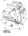
- FIG. 10 is a perspective view of a seat upholstery obtained by implementing said method,
- FIG. 11 is a sectional view of a variant of packing, obtained by the method of the invention,
- FIG. 12 is a detailed perspective view of another variant,
- FIG. 13 is a detailed perspective view of another embodiment during dressing,
- FIGS. 14 and 15 are sectional views of a seat back or seat dressed in accordance with the invention on its two faces, respectively, before assembly and after,
- finally, FIGS. 16, 17 and 18 are views of an accessory instrument according to the invention, respectively in perspective and in sections through two perpendicular planes.
La machine à coudre représentée à titre d'exemple aux figures 1, 2 et 3 est une machine à surjeter de type traditionnel comprenant un pied de biche 1, une aiguille 2 (ou éventuellement plusieurs) et des crochets (en l'exemple au nombre de deux) dont l'un est visible en 3 à la figure 1. Ces moyens sont associés à des moyens d'alimentation en fils auxiliaires 4 et à des moyens d'entraînement classiques, aptes à les mouvoir de façon appropriée pour confectionner des points de surjets. A la figure 1, on a supposé que la machine était alimentée au moyen de trois fils auxiliaires 4 en vue de réaliser un surjet à trois fils:
- deux de ces fils sont travaillés par les deux crochets 3 afin de serpenter sur une face et sur l'autre, en s'accrochant ensemble le long d'une ligne d'accrochage -La- proche du bord de la pièce de tissu,
- l'autre fil est travaillé
par l'aigui 1le 2 afin de réaliser à travers la matière une ligne de piqure -Lp- maintenant les deux autres fils.
- two of these threads are worked by the two
hooks 3 in order to meander on one side and on the other, by hanging together along a hanging line -La- close to the edge of the piece of fabric, - the other wire is worked by the
needle 1 the 2 in order to achieve through the material a line of sting -Lp- holding the two other wires.
Ces moyens et leur fonctionnement sont en eux-mêmes bien connus et ne seront pas décrits plus en détail.These means and their operation are in themselves well known and will not be described in more detail.
Selon la présente invention, la machine est dotée d'une bobine d'alimentation en un fil supplémentaire, dit fil de tension 5, de diamètre plus important que les fils auxiliaires 4 (en particulier bobine d'alimentation en elle-même de type classique, qui n'a pas été représentée).According to the present invention, the machine is provided with a coil for supplying an additional wire, known as
En outre, un tube rigide descendant 6 est fixé sur le front de la machine par une patte 7. Ce tube est agencé pour guider le fil de tension issu de la bobine d'alimentation jusqu'au voisinage du pied de biche 1, en regard de la partie amont de celui-ci.In addition, a
Un tube souple 8 de diamètre plus faible que le précédent est solidarisé au pied de biche 1 par une pièce de maintien 9, de façon qu'une de ses extrémités pénètre dans le tube rigide 6.A
L'autre extrémité de ce tube souple 8 vient se situer en regard d'un tunnel 10 qui est ménagé longitudinalement dans le pied de biche de façon à s'ouvrir sous celui-ci. Le tube souple 8 forme ainsi un passage continu entre le tube rigide 6 et le tunnel 10, et sa souplesse lui permet de se prêter aux mouvements du pied de biche.The other end of this
Le tunnel 10 est formé par une échancrure ménagée sous le pied de biche en bordure de celui-ci; cette échancrure est latéralement obturée par une pièce en forme d'équerre 11 fixée sur le pied de biche à l'aide d'une vis 12. Le tunnel est ainsi transversalement positionné par rapport aux pied de biche, aiguille et crochets, de façon à guider le fil de tension 5 à un niveau intermédiaire entre la ligne de piqûre Pq et la ligne d'accrochage Pa du surjet.The
Ainsi, comme l'illustrent les figures 4, 5 et 6, le fil de tension 5 se déroule en continu et est guidé pour s'aligner en bordure de la pièce de tissu (référencée en 25 sur ces figures), de sorte que le surjet se confectionne au-dessus du fil 5 et l'emprisonne dans le passage longitudinal -P- préservé entre les ligne de piqûre Lp et ligne d'accrochage La. Dans ce passage, le fil de tension 5 reste libre de coulisser longitudinalement. Il est à noter qu'aucune difficulté n'est rencontrée aux angles: il suffit de tourner la pièce de tissu de la façon habituelle par rapport à la machine.Thus, as illustrated in FIGS. 4, 5 and 6, the
Lorsque le surjet a été réalisé sur toute la bordure de la pièce de tissu, le fil de tension est coupé en laissant des longueurs de dépassement 5a, 5b à ses deux extrémités (figure 5).When the overlock has been made on the entire edge of the piece of fabric, the tension thread is cut, leaving protruding
La pièce de tissu peut alors être plissée en exerçant des tractions en sens opposés sur ces longueurs, afin de raccourcir la longueur engagée dans le passage précité.The piece of fabric can then be pleated by pulling in opposite directions over these lengths, in order to shorten the length engaged in the aforementioned passage.
Dans l'exemple de la figure 5, la pièce de tissu est directement équipée du fil de tension 5, en piquant les fils auxiliaires directement dans la matière de celle-ci, avec mise en place simultanée dudit fil de tension.In the example of FIG. 5, the piece of fabric is directly equipped with the
Il est également possible d'utiliser un ruban auxiliaire 13 tel que représenté à la figure 7. Ce ruban comprend en bordure un fil de tension courant le long de celui-ci; ce fil de tension est retenu comme précédemment par des fils auxiliaires piqués au moyen de la machine ci-dessus décrite.It is also possible to use an
Ainsi, des rubans tels que 13 pourront être mis à la disposition des utilisateurs afin de leur éviter d'avoir à s'équiper d'une machine à surjeter modifiée: une simple machine à coudre traditionnelle suffit alors pour piquer le ruban en bordure de la pièce de tissu concernée.Thus, ribbons such as 13 can be made available to users in order to avoid them having to equip themselves with a modified overlock machine: a simple traditional sewing machine is then enough to stitch the ribbon at the edge of the affected piece of fabric.
Par ailleurs, le plissage d'une pièce de tissu 25 munie d'un fil de tension comme expliqué plus haut est décrit ci-après dans le cadre de l'application du procédé à l'habillage d'une garniture de siège.Furthermore, the pleating of a piece of
Ce plissage et cet habillage sont réalisés au moyen d'une presse telle que représentée à la figure 8.This pleating and this covering are carried out by means of a press as shown in FIG. 8.
Ladite presse comprend un bâti 14 qui porte un plateau horizontal 15, en l'exemple circulaire. Ce plateau est monté sur des moyens de pivotement tels que butée à bille 16, autorisant sa rotation autour d'un axe central perpendiculaire à son plan (en l'exemple axe vertical).Said press comprises a
Au-dessus du plateau 15, est disposée une plaque mobile de compression 17 qui est portée par un vérin 18 pour pouvoir être déplacée verticalement en regard du plateau; de la même façon que le plateau, des moyens de pivotement tels que butée à bille 27 sont intercalés pour permettre de faire tourner la plaque autour du même axe vertical que le plateau.Above the
De plus, la presse est équipée sur deux côtés du plateau et au-dessus de celui-ci, de deux griffes de préhension telles que 19. Chaque griffe 19 est, en l'exemple, du type connu comprenant une plaquette de blocage 19a à arête avant dentée, articulée dans un cadre 19b: elle est ainsi apte à bloquer une extrémité de fil qui a été engagée dans ladite griffe comme le montre le détail de la figure 8.In addition, the press is equipped on two sides of the plate and above it, with two gripping claws such as 19. Each
Les deux griffes 19 sont situées en face l'une de l'autre et montées sur des vérins à double effet 20 aptes à les rapprocher ou à les écarter dans un plan sensiblement parallèle à celui du plateau. Ces vérins sont de préférence fixés sur des supports 21 permettant d'en régler la position en fonction du type de garniture à habiller.The two
Les vérins 20, en l'exemple de nature pneumatique, sont commandés de façon synchronisée au moyen d'une pédale 22.The
Les figures 9a à 9e illustrent le procédé mis en oeuvre au moyen de ladite presse d'habillage.Figures 9a to 9e illustrate the process implemented by means of said covering press.
Une forme de maintien 23 est posée au centre du plateau 15; elle possède des bords relevés 23a et sa forme est adaptée à celle de la garniture 24 à habiller.A holding
Cette garniture 24 est composée d'un support rigide 24a et d'une couche élastique de mousse 24b. Sa housse référencée en 25 est formée par une pièce de tissu du type de celle de la figure 5. Ladite pièce préalablement découpée à la forme de la garniture avec une marge supplémentaire 25a est donc munie du fil de tension 5 en bordure de cette marge.This lining 24 is composed of a
La pièce de tissu 25, la couche de mousse 24b et le support rigide 24a sont superposés dans la forme 23 comme l'illustre la figure 9a, la marge 25a de la pièce se trouvant relevée par les bords 23a de la forme. L'opérateur tourne le plateau 15 pour disposer les deux extrémités du fil de tension du côté des griffes 19.The piece of
La plaque 17 est ensuite abaissée par action du vérin 18, jusqu'à comprimer la couche élastique 24b (figure 9b).The
Les griffes 19 sont alors rapprochées l'une de l'autre par action de leur vérin pneumatique 20 (figure 9c). L'opérateur croise les extrémités du fil de tension pour accrocher chacune d'elles sur la griffe opposée.The
Les griffes 19 sont ensuite écartées par action des vérins 20 (figure 9d). Au cours de leur mouvement, elles exercent sur les extrémités 5a, 5b des tractions qui resserrent et plissent la marge 25a, laquelle vient se rabattre contre la face postérieure du support rigide. Une excellente régularité des plis est obtenue en soumettant le plateau 15 à de petits mouvements de rotation dans un sens et dans l'autre (flèche R de la figure 5d: les butées à bille 16 et 27 autorisent cette rotation en position de compression).The
Les extrémités du fil de tension sont alors bloquées, par exemple par agrafage au moyen d'une agrafe 26, au dos du support rigide lorsque ce support est en bois ou analogue (figure 9e). Ces extrémités peuvent alors être coupées au voisinage de l'agrafe 26.The ends of the tension wire are then blocked, for example by stapling by means of a staple 26, on the back of the rigid support when this support is made of wood or the like (FIG. 9e). These ends can then be cut in the vicinity of the
Le procédé ci-dessus décrit autorise des économies de main d'oeuvre qui peuvent être évaluées à environ 50 % par rapport au procédé classique consistant à tirer la housse manuellement à l'arrière du support rigide, puis à agrafer celle-ci sur tout le pourtour.The method described above allows savings in labor which can be estimated at around 50% compared to the conventional method of pulling the cover manually behind the rigid support, then stapling it over the whole around.
On obtient une garniture telle que représentée de dos à la figure 10, qui possède de remarquables qualités de finition. Le procédé de l'invention permet de ne laisser qu'une marge M très étroite à l'arrière de la garniture, afin de réduire les consommations de tissu. De plus, le bord surjeté du tissu bénéficie d'une netteté parfaite sans aucun risque d'effilochage. Il est possible, le cas échéant, de déplacer ultérieurement les plis périphériques de la housse pour améliorer encore leur répartition. Rien n'empêche ensuite de fixer quelques agrafes autour de la housse pour figer celle-ci dans sa meilleure configuration.A packing is obtained as shown from the back in Figure 10, which has remarkable finishing qualities. The process of the invention makes it possible to leave only a very narrow margin M behind the lining, in order to reduce the consumption of fabric. In addition, the serged edge of the fabric benefits from perfect clarity without any risk of fraying. It is possible, if necessary, to move the peripheral folds of the cover subsequently to further improve their distribution. Nothing prevents then fixing a few staples around the cover to freeze it in its best configuration.
Le fil de tension 5 peut être de tout type: fil, synthétique, naturel ou le cas échéant fil métallique. Dans ce dernier cas, une longueur de dépassement peut être laissée en attente pour être fixée ultérieurement sur une partie métallique du siège telle que son pied: l'invention fournit ainsi un moyen simple pour éviter les accumulations de charges électrostatiques sur le siège.The
La figure 11 représente en coupe une garniture similaire à la précédente, mais dans laquelle le support rigide 28 est muni sur chant d'une saignée 29. La housse est réalisée de sorte que son fil de tension vienne se positionner en regard de cette saignée après repliage de la marge. Lors des tractions sur ses extrémités, ce fil de tension s'insère dans ladite saignée et vient se resserrer dans celle-ci. Le blocage des extrémités peut être assuré par tout moyen et notamment par une agrafe si le support est en bois ou analogue.Figure 11 shows in section a lining similar to the previous one, but in which the
Par ailleurs, la figure 12 représente, en perspective partielle, une autre variante de garniture, dans laquelle le support rigide est préalablement muni, lors de sa fabrication, d'un ergot 30, en saillie sur sa face postérieure, au voisinage de chaque angle. Cet ergot peut être rapporté par clouage, vissage... dans le cas d'un support en bois ou provenir d'une découpe emboutie dans le cas d'un support métallique. Lorsqu'il est resserré, le fil de tension vient en appui contre ces ergots 30 (du côté externe) de sorte que l'effet de resserrement se trouve limité au niveau des angles. On évite ainsi une tension trop accrue sur la pièce de tissu dans les zones de très fortes courbures.Furthermore, FIG. 12 represents, in partial perspective, another variant of the lining, in which the rigid support is previously provided, during its manufacture, with a
La figure 13 montre un mode possible de blocage des extrémités du fil de tension dans le cas d'un support rigide métallique (où un agrafage n'est pas possible). Ce support est préalablement muni lors de sa fabrication d'un (ou plusieurs) ergot 31 en saillie à l'emplacement des extrémités du fil de tension (découpe emboutie). A l'endroit où les extrémités se croisent, la marge du tissu est amenée à passer sous cet ergot et celui-ci est refermé vers le support (flèche F) pour coincer lesdites extrémités après tractions.FIG. 13 shows a possible method of blocking the ends of the tension wire in the case of a rigid metal support (where stapling is not possible). This support is previously provided during its manufacture with one (or more) lug 31 protruding at the location of the ends of the tension wire (stamped cut). At the point where the ends cross, the margin of the fabric is caused to pass under this lug and the latter is closed towards the support (arrow F) to wedge said ends after pulling.
Le procédé de l'invention est particulièrement bien adapté pour réaliser des dossiers ou assises de siège revêtus sur leurs deux faces, comme le schématisent les figures 14 et 15. Une garniture 32 du type précédent est réalisée avec un support rigide doté sur son pourtour de moyens d'emboîtement, en particulier d'une moulure périphérique d'emboîtement 33; cette garniture est habillée par le procédé de l'invention, notamment en resserrant le fil de tension de sa housse dans la moulure 33.The method of the invention is particularly well suited for producing seat backs or seat covers coated on their two faces, as shown in FIGS. 14 and 15. A lining 32 of the preceding type is produced with a rigid support provided on its periphery with nesting means, in particular of a
Une plaque 34, dotée sur son pourtour de moyens d'emboîtement conjugués de ceux de la garniture (en l'exemple collerette d'emboîtement 35 de forme et d'élasticité adaptées), est habillée de façon analogue au moyen d'une housse. Le fil de tension peut être resserré sur la face postérieure de la collerette d'emboîtement.A
La garniture 32 et la plaque 34 sont ensuite présentées dos à dos de façon que leurs faces habillées soient en opposition, et sont emboîtées et serties en amenant leurs moyens d'emboîtement à coopérer.The lining 32 and the
Par ailleurs, l'opération de tractions sur les extrémités du fil de tension peut être exécutée dans certaines applications (habillage effectuée sans l'aide d'une presse, ou tout autre plissage de tissu) au moyen d'un instrument du type représenté aux figures 16, 17 et 18.Furthermore, the pulling operation on the ends of the tensioning thread can be carried out in certain applications (dressing carried out without using a press, or any other pleating of fabric) by means of an instrument of the type shown in Figures 16, 17 and 18.
Cet accessoire de faible taille pour pouvoir être tenu en main comprend un support 36 qui peut être constitué par un carter de forme plate. Sur celui-ci, sont montés deux plots rotatifs 37, 38 disposés en face l'un de l'autre. Chaque plot est doté de moyens de coincement d'une extrémité de fil.This small accessory to be able to be held in hand comprises a
En l'exemple, chaque plot est réalisé en un matériau légèrement élastique et ces moyens de coincement sont constitués par une simple fente diamétrale 39 ménagée dans chaque plot. Les deux fentes des plots sont initialement disposées dans des plans parallèles (ou même légèrement divergent) comme l'illustre la figure 16, avec un pan coupé sur les moitiés en regard, de façon à pouvoir guider et bloquer parfaitement les extrémités de fil en positions croisées.In the example, each pad is made of a slightly elastic material and these wedging means consist of a simple
Un organe manuel tel que poignée 40 permet d'entraîner ces plots par l'intermédiaire d'un mécanisme de transmission logé dans le support 36; ce mécanisme se compose en l'exemple d'un pignon 41 solidaire de la poignée, d'un pignon 42 solidaire du plot 37 et agencé en prise directe avec le pignon 41, et d'un pignon 43 solidaire de l'autre plot 38 et agencé en prise avec un pignon intermédiaire 44. Les deux plots 37 et 38 tournent ainsi en sens opposés lorsque la poignée est entraînée en rotation. Les pignons sont dimensionnés pour que ces rotations opposées s'effectuent à vitesse égale.A manual member such as
En outre, un organe anti-retour, tel que roue à rochet 45 et cliquet 46, n'autorise la rotation du mécanisme que dans un sens afin d'éviter un retour après tractions sur les extrémités de fil.In addition, a non-return member, such as
L'instrument ci-dessus décrit permet d'exercer, de façon pratique et sans effort, des tractions bien définies sur les extrémités du fil de tension lorsque celui-ci doit être resserré pour engendrer le plissage.The above-described instrument makes it possible to exert, in a practical and effortless manner, well-defined pulls on the ends of the tension thread when the latter must be tightened to cause wrinkling.
Claims (23)
Priority Applications (1)
| Application Number | Priority Date | Filing Date | Title |
|---|---|---|---|
| AT86202035T ATE56760T1 (en) | 1985-11-20 | 1986-11-17 | METHOD OF WRAPPING ARTICLES, MEANS OF ITS PERFORMANCE AND PRODUCT. |
Applications Claiming Priority (2)
| Application Number | Priority Date | Filing Date | Title |
|---|---|---|---|
| FR8517743A FR2590284B1 (en) | 1985-11-20 | 1985-11-20 | PROCESS FOR PLEATING A FLEXIBLE PART, APPLICATION TO THE DRESSING OF OBJECTS, MEANS OF PROCESSING AND PRODUCTS OBTAINED |
| FR8517743 | 1985-11-20 |
Publications (3)
| Publication Number | Publication Date |
|---|---|
| EP0223312A2 EP0223312A2 (en) | 1987-05-27 |
| EP0223312A3 EP0223312A3 (en) | 1989-08-23 |
| EP0223312B1 true EP0223312B1 (en) | 1990-09-19 |
Family
ID=9325308
Family Applications (1)
| Application Number | Title | Priority Date | Filing Date |
|---|---|---|---|
| EP86202035A Expired - Lifetime EP0223312B1 (en) | 1985-11-20 | 1986-11-17 | Method for covering objects, means therefor and products obtained |
Country Status (7)
| Country | Link |
|---|---|
| US (1) | US4732097A (en) |
| EP (1) | EP0223312B1 (en) |
| AT (1) | ATE56760T1 (en) |
| DE (1) | DE3674343D1 (en) |
| ES (1) | ES2017629B3 (en) |
| FR (1) | FR2590284B1 (en) |
| GR (1) | GR3002537T3 (en) |
Cited By (6)
| Publication number | Priority date | Publication date | Assignee | Title |
|---|---|---|---|---|
| EP0350979A1 (en) * | 1988-07-13 | 1990-01-17 | Christian Guilhem | Method and apparatus for covering an object with a fabric by means of at least one flexible cover piece |
| FR2678001A1 (en) * | 1991-06-20 | 1992-12-24 | Guilhem Christian | Method of covering objects by means of a flexible cover, means used during the implementation, and products obtained |
| US5628545A (en) * | 1992-11-06 | 1997-05-13 | Bertrand Faure Automobile "Bfa" | Method and a cover for covering a cushion of a motor vehicle seat |
| EP1039008A2 (en) | 1999-03-19 | 2000-09-27 | Rolf Völkle | Method to cover a chair and seats obtained by such a method |
| US6196148B1 (en) | 1997-07-15 | 2001-03-06 | Christian Guilhem | Sewing method and sewing machine for releasing a tension thread from a passage formed by a stitch |
| US6615354B1 (en) * | 1998-12-14 | 2003-09-02 | Hitachi, Ltd. | Information processing equipment |
Families Citing this family (15)
| Publication number | Priority date | Publication date | Assignee | Title |
|---|---|---|---|---|
| US4986055A (en) * | 1990-02-16 | 1991-01-22 | Machine Design Systems, Inc. | Cushion compression machine for compressing a cushion and applying a cover to the cushion |
| US5189772A (en) * | 1991-01-14 | 1993-03-02 | Key Plastics Sales, Inc. | Method of upholstering |
| US5187848A (en) * | 1991-10-22 | 1993-02-23 | Tachi-S Co. Ltd. | Method of assembling a seat back |
| BR9406603A (en) * | 1993-05-12 | 1996-01-02 | Nfa Corp | Upholstery seat fixing device and upholstery process |
| US5529373A (en) * | 1994-06-27 | 1996-06-25 | Hon Industries Inc. | Apparatus and method for covering a chair form with fabric |
| FR2750087B1 (en) * | 1996-06-19 | 1998-09-04 | Faure Bertrand Equipements Sa | VEHICLE SEAT ELEMENT HAVING A TENSIONED HEADPHONES ON A METAL FRAME |
| US5935364A (en) * | 1996-10-02 | 1999-08-10 | Steelcase Inc. | Thermal forming upholstery process |
| US5768761A (en) * | 1997-02-13 | 1998-06-23 | Milliken Research Corporation | Chair seat frame system |
| US5950553A (en) * | 1997-07-16 | 1999-09-14 | Lear Corporation | Method and apparatus for slidably retaining a drawstring cord within a trim cover material |
| WO2003102287A2 (en) | 2002-05-29 | 2003-12-11 | C Gex Systems C Gex | Method and machine for production of a non-unravelling seam |
| US20080246296A1 (en) * | 2007-04-03 | 2008-10-09 | Gm Global Technology Operations, Inc. | Static-Reducing Vehicle Seat |
| US8453306B2 (en) * | 2008-07-16 | 2013-06-04 | L & P Property Management Company | Method for upholstering box springs |
| DE102018202390A1 (en) * | 2018-02-16 | 2019-08-22 | Bayerische Motoren Werke Aktiengesellschaft | Motor vehicle seat, vehicle equipped therewith and method for setting a reference voltage of the motor vehicle seat |
| US11589678B2 (en) | 2019-01-17 | 2023-02-28 | Hni Technologies Inc. | Chairs including flexible frames |
| IT202000005974A1 (en) * | 2020-03-20 | 2021-09-20 | Quarrata Forniture S R L | MACHINE FOR APPLYING A LINING TO A SUPPORT |
Family Cites Families (12)
| Publication number | Priority date | Publication date | Assignee | Title |
|---|---|---|---|---|
| DE136699C (en) * | 1901-01-23 | 1902-02-01 | ||
| BE569937A (en) * | ||||
| DE564636C (en) * | 1932-11-21 | Saechsische Corsetschonerfabri | Elastic edging for items of clothing | |
| US726311A (en) * | 1901-10-02 | 1903-04-28 | Sophie Hessel | Thread-and-cord edge-finish for fabrics. |
| GB190624964A (en) * | 1906-11-06 | 1907-10-10 | William Buckler | Improvements in or relating to Knitted Garments. |
| GB190821028A (en) * | 1908-10-06 | 1909-11-08 | George Macbeth | Improvements in or connected with "Cash Registers." |
| FR553347A (en) * | 1923-05-26 | 1923-05-22 | Method and device for trapping a thread on a face of a work, by machine stitching | |
| US1717075A (en) * | 1924-08-04 | 1929-06-11 | Union Special Machine Co | Hat sweat and process of making the same |
| CH175992A (en) * | 1934-04-13 | 1935-03-31 | Singer Mfg Co | Sewing machine presser foot. |
| US2212485A (en) * | 1937-08-14 | 1940-08-20 | Sure Fit Products Company | Slip cover construction for upholstered furniture |
| US2946069A (en) * | 1956-12-17 | 1960-07-26 | Jo An Shoe Mfg Co Inc | Method of manufacturing moccasins |
| US3424161A (en) * | 1966-02-25 | 1969-01-28 | Kendall & Co | Sewn diaper with non-raveling stitching |
-
1985
- 1985-11-20 FR FR8517743A patent/FR2590284B1/en not_active Expired - Lifetime
-
1986
- 1986-11-17 DE DE8686202035T patent/DE3674343D1/en not_active Expired - Lifetime
- 1986-11-17 ES ES86202035T patent/ES2017629B3/en not_active Expired - Lifetime
- 1986-11-17 EP EP86202035A patent/EP0223312B1/en not_active Expired - Lifetime
- 1986-11-17 AT AT86202035T patent/ATE56760T1/en not_active IP Right Cessation
- 1986-11-18 US US06/932,178 patent/US4732097A/en not_active Expired - Lifetime
-
1990
- 1990-11-19 GR GR90400941T patent/GR3002537T3/en unknown
Cited By (11)
| Publication number | Priority date | Publication date | Assignee | Title |
|---|---|---|---|---|
| EP0350979A1 (en) * | 1988-07-13 | 1990-01-17 | Christian Guilhem | Method and apparatus for covering an object with a fabric by means of at least one flexible cover piece |
| FR2634190A1 (en) * | 1988-07-13 | 1990-01-19 | Guilhem Christian | METHOD AND DEVICE FOR POSITIONING AN OBJECT WITH A VIEW IN PARTICULAR OF ITS DRESSING USING A FLEXIBLE PART AND / OR ITS ASSEMBLY |
| WO1990000519A1 (en) * | 1988-07-13 | 1990-01-25 | Christian Guilhem | Process and device for covering an object using at least one flexible piece |
| FR2678001A1 (en) * | 1991-06-20 | 1992-12-24 | Guilhem Christian | Method of covering objects by means of a flexible cover, means used during the implementation, and products obtained |
| US5628545A (en) * | 1992-11-06 | 1997-05-13 | Bertrand Faure Automobile "Bfa" | Method and a cover for covering a cushion of a motor vehicle seat |
| US6196148B1 (en) | 1997-07-15 | 2001-03-06 | Christian Guilhem | Sewing method and sewing machine for releasing a tension thread from a passage formed by a stitch |
| US6615354B1 (en) * | 1998-12-14 | 2003-09-02 | Hitachi, Ltd. | Information processing equipment |
| US6631471B1 (en) * | 1998-12-14 | 2003-10-07 | Hitachi, Ltd. | Information processing equipment |
| EP1039008A2 (en) | 1999-03-19 | 2000-09-27 | Rolf Völkle | Method to cover a chair and seats obtained by such a method |
| DE19912398A1 (en) * | 1999-03-19 | 2000-09-28 | Rolf Voelkle | Process for covering the surface of a piece of seating furniture and the seat surface or backrest surface produced thereby |
| EP1039008A3 (en) * | 1999-03-19 | 2001-01-03 | Rolf Völkle | Method to cover a chair and seats obtained by such a method |
Also Published As
| Publication number | Publication date |
|---|---|
| DE3674343D1 (en) | 1990-10-25 |
| EP0223312A3 (en) | 1989-08-23 |
| EP0223312A2 (en) | 1987-05-27 |
| US4732097A (en) | 1988-03-22 |
| FR2590284B1 (en) | 1996-07-12 |
| GR3002537T3 (en) | 1993-01-25 |
| ATE56760T1 (en) | 1990-10-15 |
| ES2017629B3 (en) | 1991-03-01 |
| FR2590284A1 (en) | 1987-05-22 |
Similar Documents
| Publication | Publication Date | Title |
|---|---|---|
| EP0223312B1 (en) | Method for covering objects, means therefor and products obtained | |
| EP0243851B1 (en) | Method and apparatus for making reinforcements for pneumatic tyres | |
| CA2070566C (en) | Process for wrapping objects with a flexible cover, means used during production and products so obtained | |
| WO2006053909A1 (en) | Automatic machine for tying a knot using a string end of a tubular sleeve for sealing same by constriction when the knot is tightened | |
| EP1000189B1 (en) | Sewing method and sewing machine for releasing a tension thread from a passage formed by a stitch | |
| FR2631987A1 (en) | AUTOMATIC FEED DEVICE FOR A SEWING MACHINE USED IN PARTICULAR IN THE MANUFACTURE OF A VEHICLE SEAT | |
| BE498008A (en) | ||
| FR2631986A1 (en) | CYLINDRICAL BED SEWING MACHINE | |
| FR2621610A1 (en) | VERSATILE SEWING MACHINE | |
| FR2626201A1 (en) | Embroidered textile support, method of decorating a textile support and device enabling the said method to be implemented | |
| FR2678649A1 (en) | SEWING MACHINE. | |
| FR2768672A1 (en) | Fastening for vehicle seat cover | |
| FR2791052A1 (en) | PROCESS FOR COVERING THE AREA OF A SEAT AND THE SURFACE OF A SEAT OR BACKREST THUS MANUFACTURED | |
| EP0008986A1 (en) | Method and means for covering stuffing with an upholstery sheet | |
| FR2590600A1 (en) | Method and device for placing an elastic strip on an article of hosiery, and articles obtained according to this method | |
| FR2474071A1 (en) | Pom-pom machine - staples and cuts tow bundles at intervals | |
| FR2853915A1 (en) | Automated feeding mechanism for sewing machine comprises rotary support in sewing machine and having contour equal in shape to contour of trim cover assembly, allowing trim cover assembly to be attached and supported on rotary support | |
| FR2621789A1 (en) | Bag and method for manufacturing it | |
| FR2731691A1 (en) | Integrated fixing element for seat cover fitting, partic. automobile seats | |
| FR2648326A1 (en) | HEADREST FOR MARIEE | |
| FR2939378A1 (en) | Upholstery fixing method for frame of base/backrest of motor vehicle seat, involves rotating fixation element with respect to rod of frame until hooking portion of fixation element co-operates with another rod of frame | |
| EP0041905B1 (en) | Method of and device for adhesively securing a flexible and impervious material to a lampshade frame | |
| FR2677922A1 (en) | Composite material for the clothing and decoration industries, and the process for obtaining it | |
| FR2773826A1 (en) | Stitching to bond two overlaid fabrics | |
| FR2638069A1 (en) | METHOD AND DEVICE FOR MAKING A GARMENT STRAP SUCH AS A BRA STRAP |
Legal Events
| Date | Code | Title | Description |
|---|---|---|---|
| PUAI | Public reference made under article 153(3) epc to a published international application that has entered the european phase |
Free format text: ORIGINAL CODE: 0009012 |
|
| AK | Designated contracting states |
Kind code of ref document: A2 Designated state(s): AT BE CH DE ES FR GB GR IT LI LU NL SE |
|
| RHK1 | Main classification (correction) |
Ipc: D05B 35/06 |
|
| PUAL | Search report despatched |
Free format text: ORIGINAL CODE: 0009013 |
|
| AK | Designated contracting states |
Kind code of ref document: A3 Designated state(s): AT BE CH DE ES FR GB GR IT LI LU NL SE |
|
| 17P | Request for examination filed |
Effective date: 19890929 |
|
| 17Q | First examination report despatched |
Effective date: 19891123 |
|
| GRAA | (expected) grant |
Free format text: ORIGINAL CODE: 0009210 |
|
| AK | Designated contracting states |
Kind code of ref document: B1 Designated state(s): AT BE CH DE ES FR GB GR IT LI LU NL SE |
|
| REF | Corresponds to: |
Ref document number: 56760 Country of ref document: AT Date of ref document: 19901015 Kind code of ref document: T |
|
| REF | Corresponds to: |
Ref document number: 3674343 Country of ref document: DE Date of ref document: 19901025 |
|
| ITF | It: translation for a ep patent filed |
Owner name: DOTT. ING. FRANCO RASTELLI |
|
| GBT | Gb: translation of ep patent filed (gb section 77(6)(a)/1977) | ||
| PLBE | No opposition filed within time limit |
Free format text: ORIGINAL CODE: 0009261 |
|
| STAA | Information on the status of an ep patent application or granted ep patent |
Free format text: STATUS: NO OPPOSITION FILED WITHIN TIME LIMIT |
|
| 26N | No opposition filed | ||
| ITTA | It: last paid annual fee | ||
| REG | Reference to a national code |
Ref country code: GR Ref legal event code: FG4A Free format text: 3002537 |
|
| EPTA | Lu: last paid annual fee | ||
| EAL | Se: european patent in force in sweden |
Ref document number: 86202035.1 |
|
| REG | Reference to a national code |
Ref country code: GB Ref legal event code: IF02 |
|
| PGFP | Annual fee paid to national office [announced via postgrant information from national office to epo] |
Ref country code: GR Payment date: 20030930 Year of fee payment: 18 |
|
| PGFP | Annual fee paid to national office [announced via postgrant information from national office to epo] |
Ref country code: LU Payment date: 20031015 Year of fee payment: 18 |
|
| PGFP | Annual fee paid to national office [announced via postgrant information from national office to epo] |
Ref country code: AT Payment date: 20031130 Year of fee payment: 18 |
|
| PGFP | Annual fee paid to national office [announced via postgrant information from national office to epo] |
Ref country code: CH Payment date: 20041109 Year of fee payment: 19 |
|
| PG25 | Lapsed in a contracting state [announced via postgrant information from national office to epo] |
Ref country code: LU Free format text: LAPSE BECAUSE OF NON-PAYMENT OF DUE FEES Effective date: 20041117 Ref country code: AT Free format text: LAPSE BECAUSE OF NON-PAYMENT OF DUE FEES Effective date: 20041117 |
|
| PGFP | Annual fee paid to national office [announced via postgrant information from national office to epo] |
Ref country code: BE Payment date: 20041117 Year of fee payment: 19 |
|
| REG | Reference to a national code |
Ref country code: FR Ref legal event code: TP |
|
| PG25 | Lapsed in a contracting state [announced via postgrant information from national office to epo] |
Ref country code: GR Free format text: LAPSE BECAUSE OF NON-PAYMENT OF DUE FEES Effective date: 20050602 |
|
| PGFP | Annual fee paid to national office [announced via postgrant information from national office to epo] |
Ref country code: IT Payment date: 20050928 Year of fee payment: 20 |
|
| PGFP | Annual fee paid to national office [announced via postgrant information from national office to epo] |
Ref country code: ES Payment date: 20050930 Year of fee payment: 20 |
|
| PGFP | Annual fee paid to national office [announced via postgrant information from national office to epo] |
Ref country code: GB Payment date: 20051107 Year of fee payment: 20 |
|
| PGFP | Annual fee paid to national office [announced via postgrant information from national office to epo] |
Ref country code: SE Payment date: 20051108 Year of fee payment: 20 |
|
| PGFP | Annual fee paid to national office [announced via postgrant information from national office to epo] |
Ref country code: FR Payment date: 20051123 Year of fee payment: 20 |
|
| PGFP | Annual fee paid to national office [announced via postgrant information from national office to epo] |
Ref country code: NL Payment date: 20051129 Year of fee payment: 20 |
|
| PG25 | Lapsed in a contracting state [announced via postgrant information from national office to epo] |
Ref country code: LI Free format text: LAPSE BECAUSE OF NON-PAYMENT OF DUE FEES Effective date: 20051130 Ref country code: BE Free format text: LAPSE BECAUSE OF NON-PAYMENT OF DUE FEES Effective date: 20051130 Ref country code: CH Free format text: LAPSE BECAUSE OF NON-PAYMENT OF DUE FEES Effective date: 20051130 |
|
| PGFP | Annual fee paid to national office [announced via postgrant information from national office to epo] |
Ref country code: DE Payment date: 20051221 Year of fee payment: 20 |
|
| REG | Reference to a national code |
Ref country code: CH Ref legal event code: PL |
|
| PG25 | Lapsed in a contracting state [announced via postgrant information from national office to epo] |
Ref country code: GB Free format text: LAPSE BECAUSE OF EXPIRATION OF PROTECTION Effective date: 20061116 |
|
| PG25 | Lapsed in a contracting state [announced via postgrant information from national office to epo] |
Ref country code: NL Free format text: LAPSE BECAUSE OF EXPIRATION OF PROTECTION Effective date: 20061117 |
|
| PG25 | Lapsed in a contracting state [announced via postgrant information from national office to epo] |
Ref country code: ES Free format text: LAPSE BECAUSE OF EXPIRATION OF PROTECTION Effective date: 20061118 |
|
| REG | Reference to a national code |
Ref country code: GB Ref legal event code: PE20 |
|
| NLV7 | Nl: ceased due to reaching the maximum lifetime of a patent |
Effective date: 20061117 |
|
| EUG | Se: european patent has lapsed | ||
| REG | Reference to a national code |
Ref country code: ES Ref legal event code: FD2A Effective date: 20061118 |
|
| BERE | Be: lapsed |
Owner name: *GUILHEM CHRISTIAN Effective date: 20051130 |