EP0223291B1 - Reinforcing element of synthetic material for use in reinforced concrete, more particularly prestressed concrete, reinforced concrete provided with such reinforcing elements, and processes of manufacturing reinforcing elements, and reinforced and prestressed concrete - Google Patents
Reinforcing element of synthetic material for use in reinforced concrete, more particularly prestressed concrete, reinforced concrete provided with such reinforcing elements, and processes of manufacturing reinforcing elements, and reinforced and prestressed concrete Download PDFInfo
- Publication number
- EP0223291B1 EP0223291B1 EP86201924A EP86201924A EP0223291B1 EP 0223291 B1 EP0223291 B1 EP 0223291B1 EP 86201924 A EP86201924 A EP 86201924A EP 86201924 A EP86201924 A EP 86201924A EP 0223291 B1 EP0223291 B1 EP 0223291B1
- Authority
- EP
- European Patent Office
- Prior art keywords
- concrete
- reinforcing element
- reinforcing
- matrix
- reinforced
- Prior art date
- Legal status (The legal status is an assumption and is not a legal conclusion. Google has not performed a legal analysis and makes no representation as to the accuracy of the status listed.)
- Expired - Lifetime
Links
Images


Classifications
-
- E—FIXED CONSTRUCTIONS
- E04—BUILDING
- E04C—STRUCTURAL ELEMENTS; BUILDING MATERIALS
- E04C5/00—Reinforcing elements, e.g. for concrete; Auxiliary elements therefor
- E04C5/07—Reinforcing elements of material other than metal, e.g. of glass, of plastics, or not exclusively made of metal
- E04C5/073—Discrete reinforcing elements, e.g. fibres
-
- E—FIXED CONSTRUCTIONS
- E04—BUILDING
- E04C—STRUCTURAL ELEMENTS; BUILDING MATERIALS
- E04C5/00—Reinforcing elements, e.g. for concrete; Auxiliary elements therefor
- E04C5/07—Reinforcing elements of material other than metal, e.g. of glass, of plastics, or not exclusively made of metal
-
- Y—GENERAL TAGGING OF NEW TECHNOLOGICAL DEVELOPMENTS; GENERAL TAGGING OF CROSS-SECTIONAL TECHNOLOGIES SPANNING OVER SEVERAL SECTIONS OF THE IPC; TECHNICAL SUBJECTS COVERED BY FORMER USPC CROSS-REFERENCE ART COLLECTIONS [XRACs] AND DIGESTS
- Y10—TECHNICAL SUBJECTS COVERED BY FORMER USPC
- Y10T—TECHNICAL SUBJECTS COVERED BY FORMER US CLASSIFICATION
- Y10T428/00—Stock material or miscellaneous articles
- Y10T428/29—Coated or structually defined flake, particle, cell, strand, strand portion, rod, filament, macroscopic fiber or mass thereof
- Y10T428/2913—Rod, strand, filament or fiber
- Y10T428/2933—Coated or with bond, impregnation or core
- Y10T428/2964—Artificial fiber or filament
- Y10T428/2967—Synthetic resin or polymer
- Y10T428/2969—Polyamide, polyimide or polyester
Definitions
- Reinforced concrete more particularly prestressed concrete and processes of manufacturing reinforced and prestressed concrete
- the invention relates to reinforced concrete, including prestressed concrete, comprising one or more reinforcing elements, which are each formed by a matrix based on thermosetting synthetic material in which more than 5000 practically parallel continuous aromatic polyamide filaments are contained, the tensile strength of the filament band in the reinforcing element is higher than 2,0 GPa, the modulus of elasticity of the filament band in the reinforcing element is higher than 60 GPa and the elongation at rupture of the filament band in the reinforcing element is less than 6% to 7%, wherein the filaments form not more than 90% by volume of the reinforcing element and the synthetic matrix material forms at least 10% by volume thereof.
- the invention further comprises a process of manufacturing reinforced concrete or prestressed concrete provided with the reinforcing elements.
- the generally known phenomenon of atmospheric pollution by, int. al., carbon dioxide and agressive sulphur, chlorine and nitrogen compounds, which has shown an upward trend over the past twenty years, may in principle lead to deterioration of the steel. This air pollution not only takes place in the immediate vicinity of the industry, but also at great distances from it.
- Synthetic yarns that are melt spun from polymers such as polyethylene terephthalate, polyolefins and polyamide that do display the necessary chemical resistance generally have physical and mechanical properties, such as a very low modulus of elasticity, a high creep, etc., that render them totally unsuitable for use as an alternative to reinforcing and prestressing material for concrete.
- the reinforcing element according to the invention consisting of the special afore-mentioned combination of PPDT, PE, PVA or PAN filaments contained in a matrix of epoxy resin and/or bismaleimide resin, and the particularly favourable use thereof in reinforced or prestressed concrete are not mentioned in said publication.
- US 4 515 636 proposes the manufacture of concrete sheets reinforced with short fibres of aromatic polyamide.
- the fibres used have a length of, for instance, 6 mm and are homogeneously distributed throughout the concrete matrix.
- Such a reinforcement is uneconomical in that it requires a relatively large amount of reinforcing fibres of which a considerable proportion is present in places where no reinforcement is required.
- the strength properties of the aramid are not taken full advantage of.
- EP 0 127 198 describes composites for use in aircraft, automobiles and sporting goods. Those generally described composites are formed of an epoxy resin with a hardener and a fibre selected from the group of carbon, glass, silicon carbide, poly(benzothiazole), poly(benzimidazole), poly(benzoazole), alumina, titania, boron and aromatic polyamides.
- NL 7 108 534 describes a process of preparing reinforced, prestressed or unprestressed concrete, in which process a bundle of continuous reinforcing filaments are provided with a resin coating before they are passed into the form. It mentions various resins, viz. unsaturated polyester resin, acrylate resins, epoxy resin and polyurethane resins. As eligible filament materials are mentioned the rather conventional synthetic polymer materials, viz. polyester, polyamide and polypropylene processed by melt spinning, and polyvinyl alcohol and rayon. Although said polymers are particularly suitable for various purposes, it has been found that they are not suitable in actual practice to replace steel as reinforcing material in concrete, notably because of the fact that of the yarns described in NL 7 108 534, int. al. the physical properties, such as tensile strength and modulus of elasticity were too low and the creep was generally too high.
- EP 0 062 491 describes a process for the manufacture of a composite material formed from a matrix containing a reinforcing material of a polymer, the polymer being subjected to a plasma treatment in order to improve the adhesion to the matrix.
- suitable reinforcing materials are mentioned, int. al., (see pages 7 and 8 of said publication) film, fibrillated film or fibres in the form of monofilaments, multifilament yarn, staple fibres, optionally in the form of a fabric.
- these last-mentioned materials may consist of homo-or copolyolefins, such as polyethylene, polypropylene or a polyethylene-polyester copolymer, and also polyethylene terephthalate, nylon and aramid are mentioned.
- suitable matrix materials are mentioned thermosetting and thermoplastic resins, polyvinyl chloride, inorganic cement such as Portland or other cement.
- thermosetting matrix resins are mentioned phenolic resin, epoxy resin, vinyl ester, polyester, etc.
- GB 1 425 032 describes a band of carbon filaments held in band form by a watersoluble binding material. These bands may be impregnated with matrix material such as a polymer or cement.
- US 4 077 577 describes an asbestos-cement pipe manufactured by winding.
- the pipe consists of helical windings of aromatic polyamide filaments, the filament bundle being directly impregnated with cement.
- Japanese patent publication J 57 156 363, DE 1 925 762 and DE 2 848 731 relate to applying surface irregularities to the filaments for the purpose of improving the adhesion to a matrix.
- EP-A-0 170 499 which is only prior art according to Art. 54(3), relates to a reinforcing bar for concrete.
- Said bar comprises a plurality of threads of reinforcing fibres, which may consist of aromatic polyamide, impregnated with a hardenable material, such as epoxy resin.
- Said reinforcing bars have a substantially cylindrical configuration in cross-section.
- US 4 194 873 particularly deals with an apparatus for producing a fibre reinforced pultruded rod provided with at least one groove or protrusion.
- the reinforcing fibres may consist of Kevlar®. i.e. aromatic polyamide polyparaphenylene terephthalamide, embedded in a matrix of thermosetting resin, such as epoxy resin (see column 3, lines 1-8) and the rods may be used to reinforce concrete.
- Figs. 6-9 show rods of which the cross-section is provided with only one longitudinal groove (53) or only one longitudinal protrusion (52).
- Figs. 3, 4 and 5 show embodiments of rods with a number of grooves (53) and protrusions (52) to give rods having a multilobal cross-section. As appears from Fig.
- Japanese patent application 59-58389 was published on October 15, 1985 and corresponds to US 4 648 224.
- This patent publication also relates to a rod or tendon formed of fibre reinforced plastics for pretensioning a concrete structure.
- the rods are covered by a separate plastic adhesive layer comprising inorganic particles to achieve mechanical engagement between the rod and the concrete (see Fig. 1 + claim 1).
- the reinforcing fibres may consist of aromatic polyamide embedded in a matrix of epoxy resin (see column 2, lines 43 and 47).
- EP-A-0 170 499 US 4 648 224 only discloses rods having a circular cross-section.
- EP-A-0 199 348 also relates to a structural fibre reinforced rod for reinforcing concrete.
- the reinforcing fibres may consist of aramid filaments embedded in a thermosetting resin (see page 5, line 13 and claim 1a).
- EP-A-0 199 348 only describes the use of reinforcing rods having a substantially circular cross-section.
- EP-A-0 199 348 is only prior art according to Article 54(3).
- the invention has for its object to provide a novel reinforced concrete and reinforcing element of the type mentioned in the opening paragraph which, however, no longer displays the problems encountered with the known reinforcing elements.
- the reinforcing element in the reinforced concrete according to the invention has physical and mechanical properties which are in the same range as that of steel. Further, the reinforcing element in the concrete according to the invention is chemically resistant to the environment in which steel corrodes. Moreover, within the life time set for concrete structures the reinforcing element according to the invention is insensitive to the alkaline environment in non-carbonated concrete, so that it can also be used in direct contact with cement or concrete mortar.
- the reinforced concrete, more particularly prestressed concrete, according to the invention is in the first place characterized in that the section transverse to the longitudinal direction of the reinforcing element is substantially rectangular, particularly with the ratio of thickness to width being in the range of 1:2 to 1:90.
- Important features of the reinforcing element in the concrete according to the invention are:
- said alkali resistance of the reinforcing element in the concrete according to the invention is such that after 180 days at 80°C the residual strength of the filament band is 60-100%, more particularly about 80-100% of the initial strength.
- the reinforcing element in the concrete according to the invention is characterized in that
- the shear strength of the filament band in the reinforcing element is higher than 30 MPa and preferably about 45 MPa.
- the relaxation is less than 10%, but more particularly the relaxation is 3-5%.
- the reinforcing element is preferably characterized in that the epoxy resin is of the novolak type or is formed of a resin based on diglycidyl ether of bisphenol A or a tetrafunctional epoxy resin, such as N,N,N'N'-tetraglycidyl-4,4'-methylene bisbenzenamine, the epoxy resin being hardened by an amine curing agent, such as a cycloaliphatic amine, a dicyandiamine, an aromatic amine or a polyamine. It is also possible to apply catalytic hardening with a curing agent based on BF3.
- an amine curing agent such as a cycloaliphatic amine, a dicyandiamine, an aromatic amine or a polyamine. It is also possible to apply catalytic hardening with a curing agent based on BF3.
- an accelerator may be added to the synthetic matrix, such as an accelerator based on BF3, imidazole or dimethyl urea.
- the synthetic matrix based on epoxy resin according to the invention may in addition to the epoxy resin contain a limited amount of adjuvants, such as particular elastomeric or other thermoplastic substances or adjuvants in an amount of, say, not higher than 20% by weight, calculated on the weight of the resin, which substances may serve, for instance, to improve the elasticity of the matrix.
- adjuvants may be mentioned butadiene/styrol or substances such as polysulphone, polyether sulphone, polycarbonate or polyester.
- the thermosetting resin also may consist of a mixture or a reaction product of separate components.
- the resin also may consist of a mixture of various epoxy resins or a mixture of epoxy resin and bismaleimide resin. Or the resin may consist of a mixture of resins capable of forming interpenetrating networks.
- the reinforcing element according to the invention is characterized in that the bismaleimide resin is a resin based on 4,4'-bismaleimidodiphenyl methane. According to the invention it is preferred that in addition to 4,4'-bismaleimido diphenyl methane the synthetic matrix should contain some amount of allyl phenol, for instance in the ratio of 100:75 parts by weight.
- the filaments are so closely surrounded by the special matrix resin that the reinforcing element according to the invention is characterized in that in any random section transverse to the longitudinal direction of the reinforcing element the volume of hollow space is less than 1%, which means that said hollow space is practically nil and the internal transmission of force is therefore optimal.
- the ratio of the thickness to the width is less than 1:2.
- the ratio of the thickness to the width of the reinforcing element is in the range of 1:8 to 1:90, preferably 1:8 to 1:20.
- the width of the reinforcing element may be in the range of 10 to 50 mm, and is preferably about 20 mm, and the thickness may be in the range of 1 to 3 mm, and is preferably about 1,5 mm, and viewed in transverse direction the number of filaments is 3000 to 20 000 per mm, preferably about 5000-10 000 filaments per mm.
- the specific mass of the reinforcing element according to the invention is 1100 to 1500 kg/m3, preferably about 1300 kg/m3.
- the reinforcing element according to the invention surprisingly displays the desired chemical resistance.
- the reinforcing element according to the invention also displays a good resistance to an acid environment. Because of these properties the use of reinforcing elements according to the invention make it possible to obtain reinforced concrete, more particularly prestressed concrete, which on the strength of favourable test results is expected to have a long service life free of costly repairs in any environment.
- the chemical process taking place in the concrete as a result of air pollution and acid rain will cause no damage to the prestressed or non-prestressed concrete provided with the reinforcing elements according to the invention.
- reinforcing elements according to the invention are totally insensitive to electric or magnetic currents, as a result of which reinforced or prestressed concrete according to the invention can be used in cases where this has so far been impossible because of the sensitivity of steel, e.g. in electric traction.
- An additional advantage to the reinforcing elements according to the invention is that due to their low specific mass, i.e. a few times lower than that of steel and also lower than in the case of the known reinforcing elements of glass filaments in a matrix of polyester resin, they are easy to handle in the building industry. This contributes to somewhat lighten the generally hard working conditions in the building industry.
- the reinforcing elements of the invention formed by relatively thin strips can in a simple way be sawn to size manually or by machine.
- An important advantage of the special, substantially flat and rectangular shape of the cross-section of the reinforcing elements according to the invention consists in that the adhesion required for the transmission of force from the cement or concrete mortar to the reinforcing element, or conversely, is considerably better than in the case of a circular cross-section.
- the use of the non-circular, flattened, approximately rectangular shape of the cross-section transverse to the longitudinal direction of the reinforcing elements according to the invention permits realizing 100% transmission of force over a very limited distance both in the concrete and in the anchoring construction. Such a transmission of force has been found impossible or in any case costly and complicated if in the reinforcing elements with this type of matrix resin use is made of the circular cross-section commonly employed in steel reinforcement.
- the reinforcing element according to the invention satisfactorily adheres to the concrete matrix, the adhesion can still be further improved if according to the invention the outer surface of the reinforcing element is rough and contains a great many irregularities introduced into it for instance by rolling.
- the outer surface of the reinforcing element may contain a great many projecting fine-grained particles, in particular of inorganic material, such as particles based on silicon oxide, titanium oxide or aluminium oxide.
- the total tensile strength of the filament band in the reinforcing element according to the invention is 5 to 20% higher than the tensile strength of non-embedded filament band.
- the invention also comprises a simple process of manufacturing the reinforcing element according to the invention, in which process more than 5000, more particularly more than 15 000 practically parallel filaments are collectively embedded in a liquid synthetic material which is to serve as matrix, which is subsequently cured, particularly by subjecting it to a heat treatment, use being made of filaments having the desired mechanical properties and formed from a polymer selected from the group of aromatic polyamides, such as polyparaphenylene terephthalamide, and use being made of a matrix formed from a synthetic material based on epoxy resin and/or bismaleimide resin, more particularly an epoxy resin of the novolak type or an epoxy resin based on diglycidyl ether of bisphenol A or a tetrafunctional epoxy resin, such as N,N,N'N'-tetraglycidyl-4,4'-methylenebisbenzene amine.
- a favourable embodiment according to the invention is characterized in that the liquid epoxy resin in which the filaments are embedded contains an amine hardener, such as a cycloaliphatic amine, a dicyanodiamine, an aromatic amine or polyamine, the ratio of the amounts by weight of epoxy resin and amine hardener being in the range of 100:25 to 100:40.
- an amine hardener such as a cycloaliphatic amine, a dicyanodiamine, an aromatic amine or polyamine
- the ratio of the amounts by weight of epoxy resin and amine hardener being in the range of 100:25 to 100:40.
- a bismaleimide resin which is formed by a resin based on 4,4-bismaleimidodiphenyl methane supplemented with some amount of allyl phenol, for instance in the ratio of 100:75 parts by weight.
- the process according to the invention is advantageously characterized in that said embedding is effected by passing a filament bed having a width of at least 5 mm and a thickness of preferably not more than 3 mm under one or more preferably trough-shaped metering devices from which the mixture of liquid matrix resin is fed to the filament bed and in that the thus impregnated filament bed is passed through a curing zone for the resin preferably while subjected to a heat treatment.
- the resin may be preheated in the metering device before it is discharged therefrom.
- the filament bed provided with resin is heated to a temperature of 35°-70°C before it reaches the curing zone.
- the process for manufacturing the reinforcing element according to the invention is of particular importance for obtaining a proper embedment of the filaments in said resins.
- the resin-hardener mixture may contain a so-called accelerator, by which the curing of the epoxy resin may be speeded up.
- the process should be so carried out, for instance by embedding the filaments in vacuo, that the chance of air being entrapped in the ready reinforcing element is nil.
- proper embedment of the filaments in matrix resin as carried out in accordance with the invention is considered to result in obtaining a reinforcing element of optimum properties and quality. If during the embedment the underside of the filament bundle is free, the chance of air being entrapped will be reduced.
- the reinforcing element can in a simple manner be given the thickness desired with a view to its end use by attaching the widest side face of a formed, at least partly cured strip-shaped reinforcing element to one or more, preferably two, other identical strip-shaped reinforcing elements, preferably by means of the matrix resin.
- two at least partly cured or uncured strip-shaped reinforcing elements may with advantage each be attached to a different side of a reinforcing element by means of a still wet, practically uncured resin, after which the three reinforcing elements thus joined are passed through a curing zone.
- the reinforcing element should prior to being completely cured be gauged more particularly by means of transporting gauging rolls which are provided with recesses that correspond to the desired cross-section of the reinforcing element.
- the at least partly cured reinforcing element can be wound onto a reel having an original diameter of, say, 100 cm.
- a large number of reinforcing elements can be collectively placed in an oven for completely curing the matrix resin for several hours.
- the concrete according to the invention is characterized in that the ratio of the modulus of elasticity of the concrete matrix to the modulus of elasticity of the filament band in the reinforcing element is in the range of 1:2 to 1:6, preferably about 1:4.
- a favourable embodiment of the reinforced concrete according to the invention is characterized in that prior to curing the concrete mortar there is added to it a chloride-containing curing accelerator, for instance: 0,5 to 7% by weight of CaCl2, preferably 2 to 5% by weight, calculated on the cement weight in the concrete matrix.
- a chloride-containing curing accelerator for instance: 0,5 to 7% by weight of CaCl2, preferably 2 to 5% by weight, calculated on the cement weight in the concrete matrix.
- CaCl2 promotes the corrosion of steel, as is explained in CUR VB-84-1 published by the "Stichting voor onderzoek, voorschriften en kwaliteitseisen op het gebied van beton" ("Institute for tests, regulations and quality standards in the field of concrete").
- the chloride ions may break through the protecting passivating film on the steel.
- the reinforcing elements according to the application are properly resistant to the action of chloride ions.
- the reinforced concrete according to the invention is also characterized in that the covering or covering thickness of the concrete matrix measured between the outer surface of the concrete matrix and the circumferential surface of the reinforcing element can be practically reduced to nil and, more particularly, need be as little as 0 to less than 15 mm, preferably about 2-5 mm. Such a thin covering usually suffices to permit the transmission of the forces in the concrete to the reinforcing element and conversely.
- the conventional steel reinforcement requires a covering partly in order to protect the steel from corrosion, for instance as a result of carbonations and/or penetration of chloride ions.
- a covering layer of 15 mm or more need be applied and in the case of prestressing steel a layer of 25 mm or more; and in an agressive environment a covering of respectively 30 and 40 mm must be used.
- the present invention makes it possible for prestressed or non-prestressed concrete structures, beams, flat or corrugated sheets, respectively for floors and roofs, or other concrete elements to be manufactured particularly efficiently, considering the savings that can thus be made on material, space, future maintenance and particularly the own weight.
- the reinforced concrete according to the invention is advantageously characterized in that a number or a group of reinforcing elements extend parallel to and at some distance from each other and substantially rectilinear in practically the same plane in the concrete matrix. There may optionally be provided a second group of such reinforcing elements in such a way that the reinforcing elements of the first and the second groups extend at right angles to each other in two parallel planes.
- the invention also comprises a simple process of preparing reinforced concrete, particularly prestressed concrete, the reinforcement being placed in a form into which subsequently the concrete mortar is poured, which process is characterized in that the reinforcement is formed by one or more of the reinforcing elements according to the invention and the concrete mortar is brought into direct contact with the reinforcing elements. This is possible in that also when they are in direct contact with cement mortar or concrete mortar the reinforcing elements according to the invention are properly resistant both to non-carbonated concrete (alkaline environment) and to carbonated concrete.
- the invention also comprises a process for the preparation of prestressed concrete which is so carried out that prior to the curing of the concrete matrix each of the reinforcing elements is pretensioned while subjected to an external tensile load, said external tensile load being removed after the curing of the concrete matrix, so that in the concrete an artificial compressive stress is set up, which process is characterized in that an external tensile load of such magnitude is applied that in the cured concrete matrix the tensile stress in each reinforcing element is 40 to 70% preferably about 50%, of the tensile strength of the filament band in the reinforcing element.
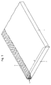
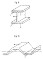
- Figure 1 is a view on a highly enlarged scale of a reinforcing element 1 according to the invention, of which the rectangular cross-section 2 has a thickness 3 of, say, 1,5 mm and a width 4 of, say, 15 mm.
- the cross-section need of course not be exactly rectangular.
- the invention not only comprises rectangular, but also more or less flattened or approximately elliptical cross-sections and the wording substantially or practically rectangular used in the claims should therefore be interpreted as such.
- the cross-section 2 consists of a very large number of PPDT filaments 5 having a diameter of 12 ⁇ m, as shown in part of the cross-section.
- the continuous filaments 5 extend uninterruptedly in longitudinal direction of the reinforcing element.
- the space between the filaments 5 is entirely filled with epoxy resin serving as a synthetic matrix.
- the reinforcing element 1 is not unduly thick and therefore sufficiently flexible, it can be marketed in the form of a roll.
- the length of reinforcing material 1 wound into such a roll may amount to a few hundred metres.
- the length of a reinforcement element required for a particular concrete structure may then be unwound from the roll and sawn off.
- the reinforcing material 1 may of course also be supplied in the form of strips of a particular length.
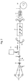
- Figure 2 is a schematic representation of an apparatus for the production of the reinforcing element 1 of the type shown in Figure 1.
- a framework (not shown) are placed a large number, say 33, of, for instance, 2 kg packages 6 of PPDT-filament yarn.
- Figure 2 shows only three of the yarn packages 6.
- the PPDT yarns 7 are of the dtex 1610/f 1000 type, which means that each yarn 7 is made up of 1000 filaments measuring 12 ⁇ m in diameter.
- the yarns 7 moving in the direction indicated by the arrow first pass over a guiding means 8 and subsequently a comb 8, so that the filaments will come to lie exactly parallel to each other.
- the filament bed is passed between a pair of brake and spread drums 11, by which the filaments are given the same tension, after which they pass under a metering slit 12 of the mixing and metering device 13 for the epoxy resin.
- the mixing and metering device 13 is filled with epoxy resin of the novolak type and a hardener of aromatic amine in the weight ratio resin-amine of 100:38.
- the filament bed 10 is free at its underside, as that under the action of gravity the resin can properly penetrate into the space between the filaments and the entire filament bed 10 is completely impregnated with resin.
- the mouth of the metering slit may still be provided with a heating device (not shown), by means of which the viscosity of the liquid epoxy resin is temporarily decreased.
- a heating zone with infrared radiators 14 by which the filament bed is heated to a temperature of 40°-70°C is provided downstream of the metering slit 12.
- the filament bed may also be preheated, for instance to a temperature of 30°-70°C, before the resin comes into contact with the filament bed.
- the filament bed impregnated with epoxy resin is covered on its upper and under side with embossed or non-embossed paper release strips 15 and 16 and subsequently passed into a heated curing zone 17, in which the impregnated filament bed is heated to a temperature of about 120°C.
- the length of the curing zone 17 must be such that at its exit the resin is partly cured. At a travelling speed of 5 m/min the length of the curing zone 17 must be approximately 10 m.
- the reinforcing element 1 is forwarded through the apparatus by means of a driving unit 21 which exerts a tensile force on the reinforcing element. Downstream of the driving unit 21 is a take up device 22 on which a large length of the produced reinforcing element 1 can be wound. Alternatively, the reinforcing element can be sawn into straight pieces of the desired length and collected.
- the reinforcing element must still be cured, to which end several rolls or a large number of straight pieces of reinforcing material are collectively left in an oven for, say, 8-10 hours, during which time they are subjected to a temperature of about 120°C to 180°C, depending on the type of resin, after which the reinforcing elements 1 according to the invention are completely ready for use and possess their final properties.
- filaments are not of polyparaphenylene terephthalamide but of polyethylene, polyvinyl alcohol or polyacrylonitrile, a similar manufacturing process may be used.
- the filament bed 10 should be completely impregnated with resin. Therefore, the thickness of the filament bed passing under the metering slit 12 should be relatively small. As a result, the thickness of the reinforcing element 1 to be produced in a single pass will be somewhat restricted.
- Thicker reinforcing elements 1 can be made in a simple manner by bonding together two, three or more partly cured reinforcing elements 1, to which end again use is made of the matrix resin as adhesive.
- one filament bed in which the resin is still wet and practically uncured may be provided between two already partly cured reinforcing elements. The resulting combination of two, three or more layers of elements must then be adequately cured.
- the reinforcing elements according to the invention can be made to have practically any desired thickness.
- the quality of the multi-layer reinforcing element 1 according to the invention is such that the behaviour of the endproduct is identical with that of a single layer reinforcing element.
- a reinforcing element 1 according to the invention is to be composed of several layers in the way as described, then use may also be made of a continuous production apparatus. To that end for instance several of the production lines schematically indicated in Fig. 2 may be superimposed and the separate layers will then have to be joined and bonded together in a suitable device. If in the described described way two relatively thin layers of 33 000 filaments each are combined with a layer of 34 000 filaments, a final reinforcing element with in all 100 000 filaments will be obtained. In principle it will be possible to manufacture a reinforcing element according to the invention containing 400 000 to 600 000 or 1 000 000 or more filaments, depending on the application envisaged.
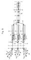
- FIG 3 shows a somewhat different production process, the parts corresponding to those in Figure 2 being referred to by like numerals.
- Three superimposed groups of PPDT filament yarns are impregnated in heatable baths 23 containing a mixture of liquid epoxy resin and hardener. After leaving the impregnating bath 23 each of the three filament beds passes through a pair of squeezing rolls 24 and subsequently through a heated precuring zone 25. After leaving the precuring zone 25 the three preheated elements 26 are joined by means of a pair of pressure and gauging rolls 27 and passed as one element through a communal, heated postcuring zone 28.
- the postcuring zone 28 there may be provided a special device (not shown) for feeding (in the direction of the arrows 29) sand, a mixture of sand and resin or some other agent to the element 1 in order to obtain a reinforcing element 1 according to the invention with a rough outer surface.
- a special device for feeding (in the direction of the arrows 29) sand, a mixture of sand and resin or some other agent to the element 1 in order to obtain a reinforcing element 1 according to the invention with a rough outer surface.
- the reinforcing element After leaving the postcuring zone 28 the reinforcing element is wound up or cut into straight pieces of some limited length.
- a driving unit 21 with which the reinforcing element 1 is pulled through the curing zone 28. Then the freshly produced reinforcing element is still to be finally hardened, to which end a large number of straight pieces are collectively placed in the oven. If the three groups of starting yarns each contain 50 000 filaments, then the reinforc
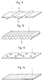
- Figures 4 and 5 are perspective views of concrete slabs B and C prestressed with reinforcing elements 1 according to the invention.
- said two concrete slabs in reality measure 1,70 ⁇ 0,20 ⁇ 0,04 m.
- the slabs B and C are merely practical examples of prestressed concrete slabs according to the invention.
- the slabs B, C and A according to Figures 4, 5 and 6 were made in reality and were tested by subjecting them to the four-point bending test, which is schematically illustrated in Figure 7, in which test as a function of the load 2P in Newton the deflection f in mm in the various stages was measured. Of each of the types B and C two slabs were made and tested.
- the slabs B according to Figure 4 are centrially pretensioned with 8 single reinforcing elements 1 (cross dimensions 20 ⁇ 0,25 mm and 22 000 filaments of ⁇ 12 ⁇ m).
- the slabs C according to Figure 5 are eccentrically pretensioned with four single reinforcing elements 1 (cross dimensions 20 ⁇ 0,25 mm and 22 000 filaments of ⁇ 12 ⁇ m).
- the concrete mortar for the test slabs A, B and C was composed as follows:
- the concrete slabs A, B and C shown in fig. 6, 4 and 5 and made and composed in the afore-described manner were subjected to two types of loading tests on the 4-point bending tester according to Figure 7.
- All slabs A, B and C were subjected to a bending load only up to the occurrence of visible cracking.
- the unreinforced slab A cracked immediately.
- the slabs B and C were subjected to a bending load up to the occurrence of failure.
- the load at which the first crack became visible was determined with the aid of calibrated weights.
- the loading was increased in steps of 49,05 N.
- the loading was raised (after every 2 or 3 minutes) when the deflection no longer increased. Table 1 gives a summary of the results.
- FIGs 11-16 are very schematic views in perspective of the reinforcing element 1 according to the invention, provided with different outer surfaces for improving the adhesion to the concrete matrix.
- the reinforcing element 1 is on both sides provided with ribs 34 which are staggered relative to each other.
- both sides of the reinforcing element 1 are entirely in the form of a serrated surface 35.
- Figure 13 shows a reinforcing element 1 which is provided with pyramidal projections 36.
- Figure 14 shows a reinforcing element 1 of which the surface contains a large number of sand granules schematically indicated with dots.
- Figure 15 shows a reinforcing element 1 whose surface is provided with studs 37.
- Figure 16 shows an embodiment of a reinforcing element 1 provided with a grid-shaped pattern of ribs 38, which may be introduced by rolling.
- the reinforcing elements 1 according to the invention are particularly insensitive to corrosion, they need be covered with only a very thin layer of concrete, which leads to a considerable saving on weight and cost of material.
- the invention is not at all limited to the concrete elements shown in the Figures. The scope of the present invention allows of many other concrete constructions and concrete elements.
- an important feature of the reinforcing elements 1 according to the invention consists in that they display a particularly good resistance to the action of an alkaline environment.
- the alkaline resistance mentioned in the claims is meant a property which is determined in the following manner: An adequate number of test specimens of the reinforcing elements according to the invention are placed freely in a liquid bath of a saturated Ca(OH)2 solution and a temperature of 80°C. After a period of 180 days at least 6, but preferably 10 test specimens are taken out of the bath. Then these test specimens are washed in water, dried to air of 55°C and subsequently stored in a conditioned room having a normalized climate (23°C, 65% relative humidity).
- the tensile strength of the filament band contained in it is determined in conformity with ASTM 3039/76. From the values found the average tensile strength is calculated. This average tensile strength is referred to as the residual strength.
- the residual strength is expressed as a percentage of the tensile strength referred to as the initial strength of the reinforcing element not exposed to any environment. Said initial strength must be determined sufficiently accurately and in the same way, i.e. in conformity with ASTM 3039/76, on reinforcing elements that have not been exposed to any environment and are of the same composition as regards the filaments and the matrix and made in the same way as the reinforcing elements that were exposed to said saturated Ca(OH)2 solution.
- the alkaline resistance of the reinforcing element according to the invention is expected to be such that after 180 days at 80°C the residual strength of the filament band in the reinforcing element will be more than 80% of the initial strength. If after 180 days at 80°C the residual strength of a filament band in the reinforcing element is more than 40% of the initial strength, then the reinforcing element has the alkaline resistance according to the invention. Insight into the reinforcing element 1 's alkaline resistance after a very long time, after for instance 50 or 100 years, is obtained by carrying out the following experiments: A number of test specimens are placed freely in several liquid baths which all contain a saturated Ca(OH)2 solution.
- the baths have temperatures of 20°C, 40°C, 60°C, 80°C and 95°C. After certain periods, viz. after 45, 90, 180 and 360 days at least 6, but preferably 10 test specimens are taken from each bath. Subsequently, these test specimens are washed with water, dried to air of 55°C and then stored in a conditioned room having a normalized climate (23°C, 65% relative humidity). Following the conditioning of the test specimens the tensile strength of the filament band contained therein is determined. Of each series of test specimens the average tensile strength is determined (also in accordance with ASTM 3039/76). This average tensile strength is referred to as residual strength.
- the residual strength is expressed as a percentage of the tensile strength (referred to as initial strength, determined as described before) of the reinforcing element that has not been exposed to any medium.
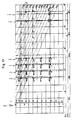
- the percentages thus found are plotted in a so-called Arrhenius graph, which is given in Figure 17.
- Arrhenius graph On one axis in Figure 17 is plotted the log of the time in days, years and hours.
- T the temperature in degrees Kelvin.
- T the temperature in degrees Kelvin.
- the corresponding values in °C are given. So on the 20°C-line in Figure 17 are four dots I-IV at the ends of periods of 45, 90, 180, 360 days, respectively.
- Each of the 20 dots of the grid represents a particular (mean) residual strength expressed as percentage of the initial strength of the starting material not exposed to a medium and/or an increase in temperature.
- contour lines or lines of constant percentage residual strength for r 95%, 90%, 85%, 80%, etc. are fixed and are drawn in the graph of Figure 17.
- these contour lines in the zone beyond the longest time (360 days) measured are extended to the drawn 50-year and 100-year lines.
- the parallel lines thus drawn represent the trends of the percentages residual strength at lower temperatures and/or longer periods.
- the dot X is now sought that corresponds to a temperature of 20°C and a period of 50 years.
- the dot X lies between the residual strength lines of 90% and 95%, so that it may be concluded that of the reinforcing element 1 for which the graph of Figure 17 is constructed the expected, extrapolated residual strength is still about 93% after 50 years at 20°C. Should the 40% residual strength line be above the X dot, then the extrapolated residual strength after 50 years would be higher than 40%. Should the 40% residual strength be below the X dot, then the extrapolated residual strength after 50 years would be less than 40%.
- the residual strength values are successively about 85%, 80%, 75% and 70% after 45, 90, 180 and 360 days, respectively.
- the lines of identical residual strength values were determined in the above described way. If the residual strength is determined on a reinforcing element according to the invention containing more than 5000 filaments, for instance: 100 000 to 1 000 000 filaments, then the residual strength will be higher and therefore more favourable than in the case of only 1000 filaments. It should be added that due to inevitable measuring errors and normal tolerances the dots for the measured percentage residual strength values need not necessarily lie exactly on the corresponding contour lines.
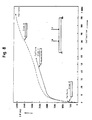
- the Y line in Figure 18 represents the residual strength at 20°C (as a percentage of the initial strength) as a function of time for a reinforcing element with 1000 filaments.
- Figure 18 also gives a Z curve for the residual strength of a reinforcing element prestressed at a load of 50% of the tensile strength. It surprisingly shows that the residual strength of a prestressed reinforcing element is even more favourable and the alkaline resistance of prestressed reinforcing elements according to the invention is even better than that of non-prestressed reinforcing elements according to the invention.
- Figure 18 still contains an S line which represents the expected variation of stress with time in a reinforcing element 1 according to the invention which is contained in concrete and which initially has a prestress of the order of 50% of the initial tensile strength.
- r ⁇ i is the value calculated with the model at the same point where r i was measured.
- estimates â1, â2 and ⁇ of the parameters (constants) a1, a2 and c, respectively, are obtained.
- the calculations can be made with a computer program for non-linear regression analysis, such as the "Statistical Software Package BMDP, Program 3R".
- the tensile strength, the elongation at rupture and the modulus of elasticity of the filament band were determined in accordance with ASTM-D 3039/76, use being of a tensile rate of 5 mm/min and fixed hydraulic grips. At the grip faces protecting strips (tabs) are provided having a thickness of 1,5-4 times the thickness of the test specimen.
- the shear strength of the reinforcing element is determined in accordance with ASTM-D 2344-84, using a span length/thickness ratio of 7:1.
- the aromatic polyamides according to the invention are polyamides that are entirely or substantially built up of repeating units of the general formula wherein A1, A2 and A3 represent the same or different divalent one or more aromatic rings-containing rigid radicals in which there may be a heterocyclic ring, of which radicals the chain extending bonds are in a position para to each other or are parallel and oppositely directed.
- radicals may be mentioned, 1,4-phenylene, 4,4'-biphenylene, 1,5-napthalene and 2,6-napthalene. They may or may not carry substituents, such as halogen atoms or alkyl groups.
- the chain molecules of the aromatic polyamides may optionally contain 50 mole % of other groups, such as m-phenylene groups, non-rigid groups, such as alkyl groups or ether, urea of ester groups, such as 3,4'-diaminodiphenyl ether groups. It is preferred that the yarn according to the invention should entirely or substantially consist of poly-p-phenylene terephthalamide (PPDT).
- PPDT poly-p-phenylene terephthalamide
- the manufacture of polyethylene filaments by solvent spinning may be carried out as described in, for instance, GB 2 042 414, GB 2 051 667 or EP 64 167.
- the manufacture of filaments of polyacrylonitrile by solvent spinning may be carried out as described in, for instance, EP 144 983 or JP Patent Application 70 449/83.
- the manufacture of filaments of polyvinyl alcohol by solvent spinning may be carried out as described in, for instance, US 4 440 711.
- concrete refers both to concrete containing natural aggregates (gravel and/or sand) and concrete containing synthetic aggregates.
- the concrete according to the invention also may contain synthetic additives.
- the relaxation is determined by loading a reinforcing element according to the invention in such a way that the length of the test specimen remains constant. To keep this length constant the force must be continuously reduced. By measuring the force at fixed moments of time the force can be plotted as a function of time. The relaxation is espressed as loss of force (in %) in a certain period, viz. from 0,1 to 1000 hours.
- the invention is of particular advantage in the case of very thin reinforced concrete elements, for instance thinner than 3 cm. Because of the insensivity to corrosion and the atmosphere such thin concrete elements can be excellently provided with the reinforcing elements according to the invention. Such thin concrete elements can actually not be reinforced with steel, unless use is made of very special and costly provisions, such as stainless steel.
- reinforcing elements according to the invention can also be used for reinforcing or prestressing cement or concrete products which for some reason are porous or waterpermeable. Mention may be made in this connection of, for instance, concrete containing aggregates such as pumic concrete or cellular concrete, woodwool cement plates, etc.
Abstract
Description
- Reinforced concrete, more particularly prestressed concrete and processes of manufacturing reinforced and prestressed concrete
- The invention relates to reinforced concrete, including prestressed concrete, comprising one or more reinforcing elements, which are each formed by a matrix based on thermosetting synthetic material in which more than 5000 practically parallel continuous aromatic polyamide filaments are contained, the tensile strength of the filament band in the reinforcing element is higher than 2,0 GPa, the modulus of elasticity of the filament band in the reinforcing element is higher than 60 GPa and the elongation at rupture of the filament band in the reinforcing element is less than 6% to 7%, wherein the filaments form not more than 90% by volume of the reinforcing element and the synthetic matrix material forms at least 10% by volume thereof. The invention further comprises a process of manufacturing reinforced concrete or prestressed concrete provided with the reinforcing elements.
- As is known, for the reinforcement of concrete and prestressed concrete use is still mainly made of steel. The use of steel is particularly based on its favourable mechanical properties, such as high strength and high modulus of elasticity and on the fact that the more or less alkaline environment in concrete and cement mortar prevents the steel contained in the concrete from being corroded; in other words the durability of reinforced concrete in the open air especially depends on the continuous presence of said alkaline environment by which the steel reinforcement is protected from corrosion. Under the influence of CO₂ in the atmosphere, however, the free lime in the concrete will be bound, as a result of which the alkalinity will decrease. Such a process is called carbonation. A decrease in the alkalinity of the concrete, particularly as soon as the pH is lower than 10, may give rise to corrosion of the steel. From the outer surface inwards the carbonation depth increases with time and as soon as the carbonation depth has become equal to the thickness of the concrete cover, the steel reinforcement may begin to rust, which in principle may lead to considerable damage of the concrete construction and may shorten its life time. The generally known phenomenon of atmospheric pollution by, int. al., carbon dioxide and agressive sulphur, chlorine and nitrogen compounds, which has shown an upward trend over the past twenty years, may in principle lead to deterioration of the steel. This air pollution not only takes place in the immediate vicinity of the industry, but also at great distances from it. As a result, the pH of rain water has in the past 10 years decreased from 6 to 5, which means a considerable increase in environmental acidity. These environmental problems are expected to become even greater in the coming years. For more details of the problems to steel as a reinforcing material reference may be had to the article "Zelfs beton vraagt aandacht" ("Even concrete requires attention"), by Ir. W.R. de Ritter, Hollandse Betongroep N.V. Dept. S & O (see the Journal: Cement of March 1983), and CUR VB-84-6, "Agressiviteit Milieu en Duurzaamheid Betonconstructies" (Agressiveness of Environment and Durability of Concrete Structures") and CUR VB-84-1 "Corrosie van de wapening in gewapende betonconstructies" ("Corrosion of the reinforcement in reinforced concrete structures") published by the "Stichting voor onderzoek, voorschriften en kwaliteitseisen op het gebied van beton" ("Institute for tests, regulations and quality standards in the field of concrete").
- Consequently, of reinforced concrete structures that have been exposed to atmospheric pollution or some agressive environments it has been found that particularly in recent years their steel reinforcement was damaged by corrosion. Durability therefore does not come up to expectations and high costs of repair must be reckoned with.
- To solve the above-described corrosion problems attempts have been made to find alternative reinforcing materials that display similar physical and mechanical properties and are not or less sensitive to steel corroding environments. Up to the present invention the only eligible materials of any practical value were glass or glass fibres. An attendant problem to a material such as glass is that although it does have the desired mechanical and physical properties and cannot be subject to corrosion, it generally displays insufficient chemical resistance to the alkaline environment (pH > 12) prevailing in non-carbonated concrete. Synthetic yarns that are melt spun from polymers such as polyethylene terephthalate, polyolefins and polyamide that do display the necessary chemical resistance generally have physical and mechanical properties, such as a very low modulus of elasticity, a high creep, etc., that render them totally unsuitable for use as an alternative to reinforcing and prestressing material for concrete.
- Research has also led to the development of non-steel reinforcing elements that have been tested on a small scale in actual practice and are formed by a matrix based on a thermosetting synthetic material in which there are more than 5000 practically parallel continuous glass filaments. Such reinforcing elements and their use in concrete and various manufacturing methods are described in the article "Kunstharz gebundene Glasfaserstäbe - eine Korrosiensbeständige Alternative zum Spannstahl" by Martin Wieser and Lothar Preis on pp. 79-85 of the book "Fortschritte im konstruktiven Ingenieurbau", published by Rolf Eligehausen and Dieter Russwurm, Verlag Ernst und Sohn, 1984, Berlin. In that article consideration is given to the replacement of prestress steel in concrete with reinforcing elements which each consist of a large number of glass filaments in a matrix of synthetic material in the form of unsaturated polyester resin. These known reinforcing elements have been successfully used outside the concrete field, especially as a result of suitable physical and mechanical properties and a good chemical resistance to various media and particularly a good resistance to acids. From the considerations on page 81 (right hand column) and page 82 in said article of Weiser and Preis, however, it appears that there are problems with regard to the resistance of these known reinforcing elements to the alkaline environment prevailing in concrete or cement mortar. Under points 4.1, 4.2 and 4.3 in said article three different solutions to these problems are discussed, mention being made of the risks and/or drawbacks to each of them. Mentioned as one of these three alternatives is a protection in the form of modifications to the synthetic matrix (of an unspecified composition) in which during loading there may be no formation of cracks down to as far as the glass filaments. Another alternative consists in providing said reinforcing element with a special sheath. As a third possibility is mentioned the use of some special injection mortar, which alternative is not only laborious but exclusively applicable in the fairly costly process of making prestressed concrete, where during the pouring of the concrete mixes room is left for channels, in which after the hardening stage the reinforcing elements are generally pretensioned, use being made of steel, corrosion sensitive anchoring elements, and the special mortar must be injected. This last-mentioned solution is so complicated and costly that instead of employing these well-known reinforcing elements of glass filaments and unsaturated polyester resin use had better be made of the less costly conventional reinforcement of prestressing steel.
- With respect to the state of the art reference is still made to the article: "Kunststof profielen met glasvezelwapening" (Glass fibre reinforced sections of synthetic material) in the journal: Metaal en Kunststof of 1983-02-14. Just as in the afore-mentioned article of Weiser and Preis special consideration is given to the product Polystal® of the firm of Bayer. As is known, the last-mentioned product consists of a great many parallel glass filaments contained in a matrix of unsaturated polyester resin. In the first column of the article in Metaal en Kunststof it says that for the matrix material also other synthetic materials may be used and that the production process also lends itself for processing other reinforcing fibres, such as carbon or aramid fibres. The reinforcing element according to the invention consisting of the special afore-mentioned combination of PPDT, PE, PVA or PAN filaments contained in a matrix of epoxy resin and/or bismaleimide resin, and the particularly favourable use thereof in reinforced or prestressed concrete are not mentioned in said publication. Although the development of concrete reinforcement consisting of bars of glass filaments embedded in a synthetic matrix dates back to 1972 and both aramid yarns and epoxy resins were already known in themselves at that time, the use in reinforced concrete of the special reinforcing element according to the invention has not been proposed. The use of continuous glass filaments in prestressed concrete has even been known since 1954 (see the article: "A preliminary investigation of the use of fibre-glass for prestressed concrete" by Ivan A. Rubinsky and Andrew Rubinsky, Magazine of Concrete Research; September 1954, p. 77). It is believed that in the generally conservative building market the man skilled in the art has been prejudiced against the use of synthetic materials in fields where they are to satisfy high strength requirements over a long period.
- In the article "Lifetime Predictions for Polymers and Composites" by R.M. Christensen, Lawrence Livermore Laboratory, University of California, in Journal of Rheology, 25 (5), pp. 517-528 (1981), p. 24, mention is made of composites of aramid yarns in epoxy resin.
- US 4 515 636 proposes the manufacture of concrete sheets reinforced with short fibres of aromatic polyamide. The fibres used have a length of, for instance, 6 mm and are homogeneously distributed throughout the concrete matrix. Such a reinforcement is uneconomical in that it requires a relatively large amount of reinforcing fibres of which a considerable proportion is present in places where no reinforcement is required. Moreover, the strength properties of the aramid are not taken full advantage of.
- EP 0 127 198 describes composites for use in aircraft, automobiles and sporting goods. Those generally described composites are formed of an epoxy resin with a hardener and a fibre selected from the group of carbon, glass, silicon carbide, poly(benzothiazole), poly(benzimidazole), poly(benzoazole), alumina, titania, boron and aromatic polyamides.
- DE 2 653 422 describes a special process for manufacturing fibre-reinforced synthetic strips. As synthetic materials are mentioned thermoplastic and thermosetting materials and a blend of epoxy resin and phenolic resin. As fibre materials are mentioned carbon and aromatic polyamide.
- NL 7 108 534 describes a process of preparing reinforced, prestressed or unprestressed concrete, in which process a bundle of continuous reinforcing filaments are provided with a resin coating before they are passed into the form. It mentions various resins, viz. unsaturated polyester resin, acrylate resins, epoxy resin and polyurethane resins. As eligible filament materials are mentioned the rather conventional synthetic polymer materials, viz. polyester, polyamide and polypropylene processed by melt spinning, and polyvinyl alcohol and rayon. Although said polymers are particularly suitable for various purposes, it has been found that they are not suitable in actual practice to replace steel as reinforcing material in concrete, notably because of the fact that of the yarns described in NL 7 108 534, int. al. the physical properties, such as tensile strength and modulus of elasticity were too low and the creep was generally too high.
-
EP 0 062 491 describes a process for the manufacture of a composite material formed from a matrix containing a reinforcing material of a polymer, the polymer being subjected to a plasma treatment in order to improve the adhesion to the matrix. As suitable reinforcing materials are mentioned, int. al., (seepages -
GB 1 425 032 describes a band of carbon filaments held in band form by a watersoluble binding material. These bands may be impregnated with matrix material such as a polymer or cement. - US 4 077 577 describes an asbestos-cement pipe manufactured by winding. In addition to the wound asbestos cement layers the pipe consists of helical windings of aromatic polyamide filaments, the filament bundle being directly impregnated with cement.
- Japanese patent publication J 57 156 363,
DE 1 925 762 andDE 2 848 731 relate to applying surface irregularities to the filaments for the purpose of improving the adhesion to a matrix. - EP-A-0 170 499, which is only prior art according to Art. 54(3), relates to a reinforcing bar for concrete. Said bar comprises a plurality of threads of reinforcing fibres, which may consist of aromatic polyamide, impregnated with a hardenable material, such as epoxy resin. Said reinforcing bars have a substantially cylindrical configuration in cross-section.
- US 4 194 873 particularly deals with an apparatus for producing a fibre reinforced pultruded rod provided with at least one groove or protrusion. The reinforcing fibres may consist of Kevlar®. i.e. aromatic polyamide polyparaphenylene terephthalamide, embedded in a matrix of thermosetting resin, such as epoxy resin (see
column 3, lines 1-8) and the rods may be used to reinforce concrete. Figs. 6-9 show rods of which the cross-section is provided with only one longitudinal groove (53) or only one longitudinal protrusion (52). Figs. 3, 4 and 5 show embodiments of rods with a number of grooves (53) and protrusions (52) to give rods having a multilobal cross-section. As appears from Fig. 1 and 2, the partially cured rods are rotated so that said grooves and/or protrusions extend helically along the rod (see Figs. 5, 7 and 9). Said rotation results in twisting of the partially cured rod (20) prior to its full cure (seecolumn 3, lines 49, 50). Said twisting is disadvantageous because in the twisted rod the reinforcing fibres will not extend parallel to the longitudinal direction of the rod and so cannot bear the maximum load. It should also be noted that US 4 194 873 does not disclose rods having a substantially rectangular cross-section as specified in the claims of the present invention. - Japanese patent application 59-58389 was published on October 15, 1985 and corresponds to US 4 648 224. This patent publication also relates to a rod or tendon formed of fibre reinforced plastics for pretensioning a concrete structure. The rods are covered by a separate plastic adhesive layer comprising inorganic particles to achieve mechanical engagement between the rod and the concrete (see Fig. 1 + claim 1). The reinforcing fibres may consist of aromatic polyamide embedded in a matrix of epoxy resin (see
column 2, lines 43 and 47). Like EP-A-0 170 499 US 4 648 224 only discloses rods having a circular cross-section. - EP-A-0 199 348 also relates to a structural fibre reinforced rod for reinforcing concrete. The reinforcing fibres may consist of aramid filaments embedded in a thermosetting resin (see
page 5,line 13 and claim 1a). Like EP-A-0 170 499, EP-A-0 199 348 only describes the use of reinforcing rods having a substantially circular cross-section. Also, EP-A-0 199 348 is only prior art according to Article 54(3). - The invention has for its object to provide a novel reinforced concrete and reinforcing element of the type mentioned in the opening paragraph which, however, no longer displays the problems encountered with the known reinforcing elements. The reinforcing element in the reinforced concrete according to the invention has physical and mechanical properties which are in the same range as that of steel. Further, the reinforcing element in the concrete according to the invention is chemically resistant to the environment in which steel corrodes. Moreover, within the life time set for concrete structures the reinforcing element according to the invention is insensitive to the alkaline environment in non-carbonated concrete, so that it can also be used in direct contact with cement or concrete mortar. The reinforced concrete, more particularly prestressed concrete, according to the invention is in the first place characterized in that the section transverse to the longitudinal direction of the reinforcing element is substantially rectangular, particularly with the ratio of thickness to width being in the range of 1:2 to 1:90. Important features of the reinforcing element in the concrete according to the invention are:
- the endless filaments are formed from aromatic polyamides, such as polyparaphenylene terephthalamide,
- the matrix is formed from a synthetic material based on epoxy resin and/or bismaleimide resin,
- the resistance to alkali of the reinforcing element determined by the method defined in the description is such that after 180 days at 80°C the residual strength of the filament band in the reinforcing element is more than 40% of the initial strength,
- the filaments form not more than 90% by volume, more particularly 40 to 70% by volume, of the reinforcing element and the synthetic matrix material forms at least 10% by volume, more particularly 60 to 30% by volume thereof. The alkali resistance of the reinforcing element in the concrete according to the invention, also when it is in direct contact with the environment of non-carbonated cement or concrete, is such that the residual strength of the filament band in the reinforcing element is higher than 40% of the initial strength, measured as indicated in the description. By extrapolation it may be inferred therefrom that after 50 years at 20°C the residual strength of the filament band in the reinforcing element will also be higher than 40% of the initial strength.
- Surprisingly, it has even been found that said alkali resistance of the reinforcing element in the concrete according to the invention is such that after 180 days at 80°C the residual strength of the filament band is 60-100%, more particularly about 80-100% of the initial strength. Further, the reinforcing element in the concrete according to the invention is characterized in that
- the tensile strength of the filament band in the reinforcing element is 2,2-4 GPa, preferably about 3 GPa,
- the modulus of elasticity of the filament band in the reinforcing element is 100-200 GPa,
- the elongation at rupture of the filament band in the reinforcing element is higher than 1,5%, and is preferably about 2,0-4%.
- If the filaments consist of polyparaphenylene terephthalamide (PPDT), then according to the invention the shear strength of the filament band in the reinforcing element is higher than 30 MPa and preferably about 45 MPa. Of the reinforcing element in the concrete according to the invention the relaxation is less than 10%, but more particularly the relaxation is 3-5%.
- According to the invention the reinforcing element is preferably characterized in that the epoxy resin is of the novolak type or is formed of a resin based on diglycidyl ether of bisphenol A or a tetrafunctional epoxy resin, such as N,N,N'N'-tetraglycidyl-4,4'-methylene bisbenzenamine, the epoxy resin being hardened by an amine curing agent, such as a cycloaliphatic amine, a dicyandiamine, an aromatic amine or a polyamine. It is also possible to apply catalytic hardening with a curing agent based on BF₃. According to the invention an accelerator may be added to the synthetic matrix, such as an accelerator based on BF₃, imidazole or dimethyl urea. The synthetic matrix based on epoxy resin according to the invention may in addition to the epoxy resin contain a limited amount of adjuvants, such as particular elastomeric or other thermoplastic substances or adjuvants in an amount of, say, not higher than 20% by weight, calculated on the weight of the resin, which substances may serve, for instance, to improve the elasticity of the matrix. As examples of said adjuvants may be mentioned butadiene/styrol or substances such as polysulphone, polyether sulphone, polycarbonate or polyester. The thermosetting resin also may consist of a mixture or a reaction product of separate components. The resin also may consist of a mixture of various epoxy resins or a mixture of epoxy resin and bismaleimide resin. Or the resin may consist of a mixture of resins capable of forming interpenetrating networks. The reinforcing element according to the invention is characterized in that the bismaleimide resin is a resin based on 4,4'-bismaleimidodiphenyl methane. According to the invention it is preferred that in addition to 4,4'-bismaleimido diphenyl methane the synthetic matrix should contain some amount of allyl phenol, for instance in the ratio of 100:75 parts by weight. Referred to as the XU 292 type, this last-mentioned resin system is elaborately described in the article "High-Performance Matrix Resin System" by T.J. Galvin, M.A. Chaudhari and J.J. King of Ciba-Geigy Corp. on pp. 45-48 of Chemical Engineering Progress January 1985. It is of course also possible to include the above-mentioned adjuvants in a matrix of bismaleimide resin. Favourable results are obtained with a reinforcing element which is characterized according to the invention in that the diameter of the filaments is 5-20 µm, preferably about 12 µm. The filaments are so closely surrounded by the special matrix resin that the reinforcing element according to the invention is characterized in that in any random section transverse to the longitudinal direction of the reinforcing element the volume of hollow space is less than 1%, which means that said hollow space is practically nil and the internal transmission of force is therefore optimal. In the present reinforcing element with the more or less flattened, approximately rectangular cross-section the ratio of the thickness to the width is less than 1:2. With advantage, however, the ratio of the thickness to the width of the reinforcing element is in the range of 1:8 to 1:90, preferably 1:8 to 1:20.
According to the invention the width of the reinforcing element may be in the range of 10 to 50 mm, and is preferably about 20 mm, and the thickness may be in the range of 1 to 3 mm, and is preferably about 1,5 mm, and viewed in transverse direction the number of filaments is 3000 to 20 000 per mm, preferably about 5000-10 000 filaments per mm. The specific mass of the reinforcing element according to the invention is 1100 to 1500 kg/m³, preferably about 1300 kg/m³.
In addition to the favourable physical and mechanical properties required for use in reinforced concrete the reinforcing element according to the invention surprisingly displays the desired chemical resistance. Particularly favourable is the resistance of the reinforcing element according to the invention to the strongly alkaline environment prevailing in the fresh concrete and in the cement mortar. The reinforcing element according to the invention also displays a good resistance to an acid environment. Because of these properties the use of reinforcing elements according to the invention make it possible to obtain reinforced concrete, more particularly prestressed concrete, which on the strength of favourable test results is expected to have a long service life free of costly repairs in any environment. Particularly, the chemical process taking place in the concrete as a result of air pollution and acid rain will cause no damage to the prestressed or non-prestressed concrete provided with the reinforcing elements according to the invention. - Further, the reinforcing elements according to the invention are totally insensitive to electric or magnetic currents, as a result of which reinforced or prestressed concrete according to the invention can be used in cases where this has so far been impossible because of the sensitivity of steel, e.g. in electric traction.
- An additional advantage to the reinforcing elements according to the invention is that due to their low specific mass, i.e. a few times lower than that of steel and also lower than in the case of the known reinforcing elements of glass filaments in a matrix of polyester resin, they are easy to handle in the building industry. This contributes to somewhat lighten the generally hard working conditions in the building industry. The reinforcing elements of the invention formed by relatively thin strips can in a simple way be sawn to size manually or by machine. An important advantage of the special, substantially flat and rectangular shape of the cross-section of the reinforcing elements according to the invention consists in that the adhesion required for the transmission of force from the cement or concrete mortar to the reinforcing element, or conversely, is considerably better than in the case of a circular cross-section. The use of the non-circular, flattened, approximately rectangular shape of the cross-section transverse to the longitudinal direction of the reinforcing elements according to the invention permits realizing 100% transmission of force over a very limited distance both in the concrete and in the anchoring construction. Such a transmission of force has been found impossible or in any case costly and complicated if in the reinforcing elements with this type of matrix resin use is made of the circular cross-section commonly employed in steel reinforcement.
- Although the reinforcing element according to the invention satisfactorily adheres to the concrete matrix, the adhesion can still be further improved if according to the invention the outer surface of the reinforcing element is rough and contains a great many irregularities introduced into it for instance by rolling. Alternatively, the outer surface of the reinforcing element may contain a great many projecting fine-grained particles, in particular of inorganic material, such as particles based on silicon oxide, titanium oxide or aluminium oxide.
- It has been found that the total tensile strength of the filament band in the reinforcing element according to the invention is 5 to 20% higher than the tensile strength of non-embedded filament band.
- The invention also comprises a simple process of manufacturing the reinforcing element according to the invention, in which process more than 5000, more particularly more than 15 000 practically parallel filaments are collectively embedded in a liquid synthetic material which is to serve as matrix, which is subsequently cured, particularly by subjecting it to a heat treatment, use being made of filaments having the desired mechanical properties and formed from a polymer selected from the group of aromatic polyamides, such as polyparaphenylene terephthalamide, and use being made of a matrix formed from a synthetic material based on epoxy resin and/or bismaleimide resin, more particularly an epoxy resin of the novolak type or an epoxy resin based on diglycidyl ether of bisphenol A or a tetrafunctional epoxy resin, such as N,N,N'N'-tetraglycidyl-4,4'-methylenebisbenzene amine.
A favourable embodiment according to the invention is characterized in that the liquid epoxy resin in which the filaments are embedded contains an amine hardener, such as a cycloaliphatic amine, a dicyanodiamine, an aromatic amine or polyamine, the ratio of the amounts by weight of epoxy resin and amine hardener being in the range of 100:25 to 100:40. According to a favourable embodiment use is made of a bismaleimide resin which is formed by a resin based on 4,4-bismaleimidodiphenyl methane supplemented with some amount of allyl phenol, for instance in the ratio of 100:75 parts by weight. The process according to the invention is advantageously characterized in that said embedding is effected by passing a filament bed having a width of at least 5 mm and a thickness of preferably not more than 3 mm under one or more preferably trough-shaped metering devices from which the mixture of liquid matrix resin is fed to the filament bed and in that the thus impregnated filament bed is passed through a curing zone for the resin preferably while subjected to a heat treatment. To reduce the viscosity the resin may be preheated in the metering device before it is discharged therefrom. According to the invention the filament bed provided with resin is heated to a temperature of 35°-70°C before it reaches the curing zone. It has been found that the process for manufacturing the reinforcing element according to the invention is of particular importance for obtaining a proper embedment of the filaments in said resins. Optionally, the resin-hardener mixture may contain a so-called accelerator, by which the curing of the epoxy resin may be speeded up. For a proper embedment of the filaments it is also of importance that the process should be so carried out, for instance by embedding the filaments in vacuo, that the chance of air being entrapped in the ready reinforcing element is nil. Notably, proper embedment of the filaments in matrix resin as carried out in accordance with the invention is considered to result in obtaining a reinforcing element of optimum properties and quality. If during the embedment the underside of the filament bundle is free, the chance of air being entrapped will be reduced. - According to the invention the reinforcing element can in a simple manner be given the thickness desired with a view to its end use by attaching the widest side face of a formed, at least partly cured strip-shaped reinforcing element to one or more, preferably two, other identical strip-shaped reinforcing elements, preferably by means of the matrix resin. Thus, according to the invention two at least partly cured or uncured strip-shaped reinforcing elements may with advantage each be attached to a different side of a reinforcing element by means of a still wet, practically uncured resin, after which the three reinforcing elements thus joined are passed through a curing zone. According to the invention the reinforcing element should prior to being completely cured be gauged more particularly by means of transporting gauging rolls which are provided with recesses that correspond to the desired cross-section of the reinforcing element. The at least partly cured reinforcing element can be wound onto a reel having an original diameter of, say, 100 cm. A large number of reinforcing elements can be collectively placed in an oven for completely curing the matrix resin for several hours.
- The concrete according to the invention is characterized in that the ratio of the modulus of elasticity of the concrete matrix to the modulus of elasticity of the filament band in the reinforcing element is in the range of 1:2 to 1:6, preferably about 1:4.
- A favourable embodiment of the reinforced concrete according to the invention is characterized in that prior to curing the concrete mortar there is added to it a chloride-containing curing accelerator, for instance: 0,5 to 7% by weight of CaCl₂, preferably 2 to 5% by weight, calculated on the cement weight in the concrete matrix. Adding CaCl₂ to the concrete mortar or cement mortar will cause the curing process to accelerate, which permits removal of the form work at an earlier stage and generally contributes to faster and more efficient building. When use is made of a reinforcement of steel, the addition of CaCl₂ is generally undesirable and virtually prohibited in the concrete specifications. CaCl₂ promotes the corrosion of steel, as is explained in CUR VB-84-1 published by the "Stichting voor onderzoek, voorschriften en kwaliteitseisen op het gebied van beton" ("Institute for tests, regulations and quality standards in the field of concrete"). For under alkaline conditions the chloride ions may break through the protecting passivating film on the steel. The reinforcing elements according to the application are properly resistant to the action of chloride ions. This has moreover the advantage that also after a number of years the concrete provided with the reinforcing elements according to the invention will not be subject to any damage either when at some later stage chloride ions will penetrate into the concrete, which may happen for instance under the influence of seawater or road salt. Consequently, the formerly often used chloride-containing hardening accelerators, whose use in steel reinforcement is severely restricted if allowed at all because of its often leading to damage, can to a practically unlimited extent be employed in the manufacture of the concrete according to the invention, as a result of which a considerable economy can be achieved.
- The reinforced concrete according to the invention is also characterized in that the covering or covering thickness of the concrete matrix measured between the outer surface of the concrete matrix and the circumferential surface of the reinforcing element can be practically reduced to nil and, more particularly, need be as little as 0 to less than 15 mm, preferably about 2-5 mm. Such a thin covering usually suffices to permit the transmission of the forces in the concrete to the reinforcing element and conversely.
- Use of the conventional steel reinforcement requires a covering partly in order to protect the steel from corrosion, for instance as a result of carbonations and/or penetration of chloride ions. In the case of steel a covering layer of 15 mm or more need be applied and in the case of prestressing steel a layer of 25 mm or more; and in an agressive environment a covering of respectively 30 and 40 mm must be used. Since in the reinforced concrete according to the invention a thin layer of concrete may be applied, the present invention makes it possible for prestressed or non-prestressed concrete structures, beams, flat or corrugated sheets, respectively for floors and roofs, or other concrete elements to be manufactured particularly efficiently, considering the savings that can thus be made on material, space, future maintenance and particularly the own weight.
- The reinforced concrete according to the invention is advantageously characterized in that a number or a group of reinforcing elements extend parallel to and at some distance from each other and substantially rectilinear in practically the same plane in the concrete matrix. There may optionally be provided a second group of such reinforcing elements in such a way that the reinforcing elements of the first and the second groups extend at right angles to each other in two parallel planes.
- The invention also comprises a simple process of preparing reinforced concrete, particularly prestressed concrete, the reinforcement being placed in a form into which subsequently the concrete mortar is poured, which process is characterized in that the reinforcement is formed by one or more of the reinforcing elements according to the invention and the concrete mortar is brought into direct contact with the reinforcing elements. This is possible in that also when they are in direct contact with cement mortar or concrete mortar the reinforcing elements according to the invention are properly resistant both to non-carbonated concrete (alkaline environment) and to carbonated concrete.
- The invention also comprises a process for the preparation of prestressed concrete which is so carried out that prior to the curing of the concrete matrix each of the reinforcing elements is pretensioned while subjected to an external tensile load, said external tensile load being removed after the curing of the concrete matrix, so that in the concrete an artificial compressive stress is set up, which process is characterized in that an external tensile load of such magnitude is applied that in the cured concrete matrix the tensile stress in each reinforcing element is 40 to 70% preferably about 50%, of the tensile strength of the filament band in the reinforcing element.
- The invention will be further described with reference to a few schematic drawings.
- Figure 1
- is a view in perspective of the reinforcing element according to the invention.
- Figure 2
- shows an apparatus for manufacturing the reinforcing element according to the invention.
- Figure 3
- shows a variant apparatus for manufacturing the reinforcing element according to the invention.
- Figures 4 and 5
- are perspective views of slabs of reinforced concrete according to the invention.
- Figure 6
- shows a non-reinforced concrete slab.
- Figure 7
- shows the set-up used in the four-point flexural strength test.
- Figure 8
- shows the load-deflection diagram.
- Figure 9
- is a view in perspective of an I-section of reinforced concrete according to the invention.
- Figure 10
- is a view in perspective of a corrugated sheet of reinforced concrete according to the invention.
- Figures 11-16
- show various embodiments for the surface of the reinforcing element according to the invention.
- Figure 17
- is the Arrhenius diagram for determining the residual strengths after various residence periods in an alkaline environment.
- Figure 18
- shows the residual strength in an alkaline medium as a function of time.
- Figure 1 is a view on a highly enlarged scale of a reinforcing
element 1 according to the invention, of which therectangular cross-section 2 has athickness 3 of, say, 1,5 mm and a width 4 of, say, 15 mm. The cross-section need of course not be exactly rectangular. The invention not only comprises rectangular, but also more or less flattened or approximately elliptical cross-sections and the wording substantially or practically rectangular used in the claims should therefore be interpreted as such. Thecross-section 2 consists of a very large number ofPPDT filaments 5 having a diameter of 12 µm, as shown in part of the cross-section. Thecontinuous filaments 5 extend uninterruptedly in longitudinal direction of the reinforcing element. The space between thefilaments 5 is entirely filled with epoxy resin serving as a synthetic matrix. If the reinforcingelement 1 is not unduly thick and therefore sufficiently flexible, it can be marketed in the form of a roll. The length of reinforcingmaterial 1 wound into such a roll may amount to a few hundred metres. The length of a reinforcement element required for a particular concrete structure may then be unwound from the roll and sawn off. Instead of on a roll the reinforcingmaterial 1 may of course also be supplied in the form of strips of a particular length. - Figure 2 is a schematic representation of an apparatus for the production of the reinforcing
element 1 of the type shown in Figure 1. In a framework (not shown) are placed a large number, say 33, of, for instance, 2kg packages 6 of PPDT-filament yarn. Figure 2 shows only three of the yarn packages 6. ThePPDT yarns 7 are of the dtex 1610/f 1000 type, which means that eachyarn 7 is made up of 1000 filaments measuring 12 µm in diameter. Theyarns 7 moving in the direction indicated by the arrow first pass over a guiding means 8 and subsequently acomb 8, so that the filaments will come to lie exactly parallel to each other. Subsequently, the filament bed is passed between a pair of brake and spreaddrums 11, by which the filaments are given the same tension, after which they pass under a metering slit 12 of the mixing andmetering device 13 for the epoxy resin. The mixing andmetering device 13 is filled with epoxy resin of the novolak type and a hardener of aromatic amine in the weight ratio resin-amine of 100:38. At the location of the metering slit 12 thefilament bed 10 is free at its underside, as that under the action of gravity the resin can properly penetrate into the space between the filaments and theentire filament bed 10 is completely impregnated with resin. To improve such impregnation the mouth of the metering slit may still be provided with a heating device (not shown), by means of which the viscosity of the liquid epoxy resin is temporarily decreased. For the same purpose a heating zone withinfrared radiators 14 by which the filament bed is heated to a temperature of 40°-70°C is provided downstream of the metering slit 12. For a further improvement of impregnation the filament bed may also be preheated, for instance to a temperature of 30°-70°C, before the resin comes into contact with the filament bed. Then the filament bed impregnated with epoxy resin is covered on its upper and under side with embossed or non-embossed paper release strips 15 and 16 and subsequently passed into aheated curing zone 17, in which the impregnated filament bed is heated to a temperature of about 120°C. The length of the curingzone 17 must be such that at its exit the resin is partly cured. At a travelling speed of 5 m/min the length of the curingzone 17 must be approximately 10 m. After the filament bed has left the curingzone 17, the release strips 15 and 16 are removed from the already fairly hard resin impregnated filament bed, which is then practically in the form of the reinforcingelement 1 of the present invention. In the curing zone there are pairs of gauging and guiding rolls 18, 19, 20 for fixing the proper dimensions of the cross-section of the reinforcing element. The reinforcingelement 1 is forwarded through the apparatus by means of a drivingunit 21 which exerts a tensile force on the reinforcing element. Downstream of the drivingunit 21 is a take updevice 22 on which a large length of the produced reinforcingelement 1 can be wound. Alternatively, the reinforcing element can be sawn into straight pieces of the desired length and collected. Subsequently, the reinforcing element must still be cured, to which end several rolls or a large number of straight pieces of reinforcing material are collectively left in an oven for, say, 8-10 hours, during which time they are subjected to a temperature of about 120°C to 180°C, depending on the type of resin, after which the reinforcingelements 1 according to the invention are completely ready for use and possess their final properties. - If the filaments are not of polyparaphenylene terephthalamide but of polyethylene, polyvinyl alcohol or polyacrylonitrile, a similar manufacturing process may be used.
- To obtain a reinforcing element of optimum quality it is of great importance that the
filament bed 10 should be completely impregnated with resin. Therefore, the thickness of the filament bed passing under the metering slit 12 should be relatively small. As a result, the thickness of the reinforcingelement 1 to be produced in a single pass will be somewhat restricted. Thicker reinforcingelements 1, however, can be made in a simple manner by bonding together two, three or more partly cured reinforcingelements 1, to which end again use is made of the matrix resin as adhesive. Alternatively, one filament bed in which the resin is still wet and practically uncured may be provided between two already partly cured reinforcing elements. The resulting combination of two, three or more layers of elements must then be adequately cured. In this way the reinforcing elements according to the invention can be made to have practically any desired thickness. The quality of the multi-layer reinforcingelement 1 according to the invention is such that the behaviour of the endproduct is identical with that of a single layer reinforcing element.
If a reinforcingelement 1 according to the invention is to be composed of several layers in the way as described, then use may also be made of a continuous production apparatus. To that end for instance several of the production lines schematically indicated in Fig. 2 may be superimposed and the separate layers will then have to be joined and bonded together in a suitable device. If in the described described way two relatively thin layers of 33 000 filaments each are combined with a layer of 34 000 filaments, a final reinforcing element with in all 100 000 filaments will be obtained. In principle it will be possible to manufacture a reinforcing element according to the invention containing 400 000 to 600 000 or 1 000 000 or more filaments, depending on the application envisaged. - Figure 3 shows a somewhat different production process, the parts corresponding to those in Figure 2 being referred to by like numerals. Three superimposed groups of PPDT filament yarns are impregnated in
heatable baths 23 containing a mixture of liquid epoxy resin and hardener. After leaving the impregnatingbath 23 each of the three filament beds passes through a pair of squeezingrolls 24 and subsequently through a heated precuringzone 25. After leaving theprecuring zone 25 the threepreheated elements 26 are joined by means of a pair of pressure and gaugingrolls 27 and passed as one element through a communal, heated postcuringzone 28. In the first part of the postcuringzone 28 there may be provided a special device (not shown) for feeding (in the direction of the arrows 29) sand, a mixture of sand and resin or some other agent to theelement 1 in order to obtain a reinforcingelement 1 according to the invention with a rough outer surface. After leaving thepostcuring zone 28 the reinforcing element is wound up or cut into straight pieces of some limited length. There is again provided adriving unit 21, with which the reinforcingelement 1 is pulled through the curingzone 28. Then the freshly produced reinforcing element is still to be finally hardened, to which end a large number of straight pieces are collectively placed in the oven. If the three groups of starting yarns each contain 50 000 filaments, then the reinforcingelement 1 produced in accordance with the schematically indicated process of Figure 3 will contain in all 150 000 filaments. - Figures 4 and 5 are perspective views of concrete slabs B and C prestressed with reinforcing
elements 1 according to the invention. As the unreinforced slab A of Figure 6, said two concrete slabs inreality measure - The slabs B according to Figure 4 are centrially pretensioned with 8 single reinforcing elements 1 (cross
dimensions 20 × 0,25 mm and 22 000 filaments of φ 12 µm). The total initial prestressing force was 8 × 3000 N = 24 000 N. - The slabs C according to Figure 5 are eccentrically pretensioned with four single reinforcing elements 1 (cross
dimensions 20 × 0,25 mm and 22 000 filaments of φ 12 µm). The total initial prestressing force was 4 × 3000 N = 12 000 N. - During the pretensioning of the reinforcing
elements 1 for the slabs B and C the loss of prestress was measured for 24 hours via a load cell with T.N.O.-calibration certificate (measuring accuracy ± 0,2%). The trend of the prestress losses was recorded. Immediately upon being pretensioned, all the reinforcingelements 1 were sanded over a distance of 200 mm from the ends of the slabs. Sanding was effected by using a hardwood lacquer (varnish) mixed with sand (particle size 0,125 to 0,250 mm), which was applied by brush. Or the reinforcing elements were first treated with lacquer, which was subsequently sprinkled with sand.
Immediately before casting the concrete (24 hours after pretensioning) the loss of prestress (3 to 4%) was made up to the desired prestressing level. The ends of the reinforcing elements were anchored outside the concrete element. - The same anchoring used in earlier tensile tests resulted in a force of 100% of the theoretical tensile strength of a single strip.
- In the pouring and curing operations for the slabs A, B and C the following procedure was used:
All the slabs were compacted by setting the form work into vibration. For eachslab 3 cubes with an edge of 158 mm were made. They were used for determining the cube compressive strength in the various stages of the hardening process and for determining the 28 days' splitting tensile strength. Also determined were the water/cement ratio of the concrete mortar used and the slump. All the relevant concrete data were recorded.
Following the pouring operation the slabs were cured in the laboratory for 2 × 24 hours, during which periods they were covered with a plastics sheet to prevent dehydration. The temperature in the laboratory ranged from 10° to 16°C. After demoulding (after 2 days' curing) the slabs were stored in a conditioning room at a temperature of 20°C ± 2°C and a relative air humidity of ≧ 95%.
The moment the prestress was released the reinforcingelements 1 were not found to display any slippage. - The concrete mortar for the test slabs A, B and C was composed as follows:
- Choice of the nominal particle size
In accordance with NEN 3880 (VB 1974/1984) section 603.5.1.
¾ of the smallest distance between the reinforcing elements.
The smallest distance between the reinforcing elements is 22 mm (centrically pretensioned slab B) ¾ × 22 = 16,5.
An aggregate mixture having a nominal particle size of 16 mm is chosen. - Grading of aggregate
The aggregate mixture is such that the resulting mixture displays a grading curve which falls between the boundary lines A and B according to NEN section 603.5.3. - Cement content
In accordance with NEN 3880, section 603.8.2 the minimum cement content forB
320 kg/m³.
Increase due to particle size of 16 mm is 10%:
320 + 10% = 352 kg/m³.
Use was made of: 352 kg/m³ class B Portland cement. - Consistency
In order to compact the test slabs by vibration the concrete mortar was controlled to a slump of 50-90 mm (consistency range 2) after the addition of 3% of superplasticizer Melment LIO, based on the weight of the cement. - Total swelling calculation (per m³)

- Controlling the amount of fines
In accordance with NEN 3880 section 603.6 the minimum amount of fines < 0,250 mm for a nominal particle size of 16 mm = 135 litres/m³.which is consequently sufficient.
- The concrete slabs A, B and C shown in fig. 6, 4 and 5 and made and composed in the afore-described manner were subjected to two types of loading tests on the 4-point bending tester according to Figure 7. In the first series of tests all slabs A, B and C were subjected to a bending load only up to the occurrence of visible cracking. The unreinforced slab A cracked immediately. In the second series of tests the slabs B and C were subjected to a bending load up to the occurrence of failure.
- The load at which the first crack became visible was determined with the aid of calibrated weights. The loading was increased in steps of 49,05 N. The loading was raised (after every 2 or 3 minutes) when the deflection no longer increased. Table 1 gives a summary of the results.

- After a few weeks the test slabs were loaded up to the occurrence of failure. The load was increased every 5 minutes.
The graph in Figure 8 shows the relationship between loading and deflection. It appears for instance that after the formation in it of cracks the structure can still take up a high additional load. The deflection will strongly increase then, which is a warning of overloading. - Besides the prestressed concrete slabs Band C according to the invention shown in Figures 4 and 5, with which also the afore-described flexural tests were carried out, various other prestressed or non-prestressed reinforcing concrete structures can be realized within the scope of the present invention. It is possible, for instance, to make prestressed or non-prestressed reinforced concrete sections, such as the I-
beam 31 shown in Figure 9, which is provided in itsflanges 32 with a number of reinforcingelements 1 according to the invention which extend in longitudinal direction of thebeam 31.
Figure 10 illustrates a different construction in the form of a kind of prestressed or non-prestressed reinforced concrete corrugatedsheet 33, which in the lower half to be loaded is provided with the reinforcingelements 1 according to the invention. - Figures 11-16 are very schematic views in perspective of the reinforcing
element 1 according to the invention, provided with different outer surfaces for improving the adhesion to the concrete matrix.
In Figure 11 the reinforcingelement 1 is on both sides provided withribs 34 which are staggered relative to each other.
In Figure 12 both sides of the reinforcingelement 1 are entirely in the form of aserrated surface 35.
Figure 13 shows a reinforcingelement 1 which is provided withpyramidal projections 36.
Figure 14 shows a reinforcingelement 1 of which the surface contains a large number of sand granules schematically indicated with dots.
Figure 15 shows a reinforcingelement 1 whose surface is provided withstuds 37.
Figure 16 shows an embodiment of a reinforcingelement 1 provided with a grid-shaped pattern ofribs 38, which may be introduced by rolling. As the reinforcingelements 1 according to the invention are particularly insensitive to corrosion, they need be covered with only a very thin layer of concrete, which leads to a considerable saving on weight and cost of material. The invention is not at all limited to the concrete elements shown in the Figures. The scope of the present invention allows of many other concrete constructions and concrete elements. - As mentioned before, an important feature of the reinforcing
elements 1 according to the invention consists in that they display a particularly good resistance to the action of an alkaline environment. By the alkaline resistance mentioned in the claims is meant a property which is determined in the following manner: An adequate number of test specimens of the reinforcing elements according to the invention are placed freely in a liquid bath of a saturated Ca(OH)₂ solution and a temperature of 80°C. After a period of 180 days at least 6, but preferably 10 test specimens are taken out of the bath. Then these test specimens are washed in water, dried to air of 55°C and subsequently stored in a conditioned room having a normalized climate (23°C, 65% relative humidity). Following the conditioning of the test specimens the tensile strength of the filament band contained in it is determined in conformity with ASTM 3039/76. From the values found the average tensile strength is calculated. This average tensile strength is referred to as the residual strength. The residual strength is expressed as a percentage of the tensile strength referred to as the initial strength of the reinforcing element not exposed to any environment. Said initial strength must be determined sufficiently accurately and in the same way, i.e. in conformity with ASTM 3039/76, on reinforcing elements that have not been exposed to any environment and are of the same composition as regards the filaments and the matrix and made in the same way as the reinforcing elements that were exposed to said saturated Ca(OH)₂ solution. On the strength of experiments the alkaline resistance of the reinforcing element according to the invention is expected to be such that after 180 days at 80°C the residual strength of the filament band in the reinforcing element will be more than 80% of the initial strength. If after 180 days at 80°C the residual strength of a filament band in the reinforcing element is more than 40% of the initial strength, then the reinforcing element has the alkaline resistance according to the invention.
Insight into the reinforcing element 1 's alkaline resistance after a very long time, after forinstance 
- In the graph of Figure 17 the dot X is now sought that corresponds to a temperature of 20°C and a period of 50 years. As appears from Figure 17, the dot X lies between the residual strength lines of 90% and 95%, so that it may be concluded that of the reinforcing
element 1 for which the graph of Figure 17 is constructed the expected, extrapolated residual strength is still about 93% after 50 years at 20°C. Should the 40% residual strength line be above the X dot, then the extrapolated residual strength after 50 years would be higher than 40%. Should the 40% residual strength be below the X dot, then the extrapolated residual strength after 50 years would be less than 40%. - In the graph of Figure 17 the position of the residual strength lines was calculated with said model and the measuring values are based on measurements conducted on a reinforcing element of only 1000 PPDT filaments embedded in epoxy resin. For all eight grid dots I-IV of the test specimens from baths of 20°C and 40°C a residual strength of on average about 100% was found, which percentages are mentioned at said dots in the graph of Figure 17. At 60°C the average residual strength values are successively about 100%, 100%, 95% and 90%, after 45, 90, 180 and 360 days, respectively. At 80°C the residual strength values are successively about 95%, 88%, 83% and 77%, after 45, 90, 180 and 360 days, respectively. At 95°C the residual strength values are successively about 85%, 80%, 75% and 70% after 45, 90, 180 and 360 days, respectively. The lines of identical residual strength values were determined in the above described way. If the residual strength is determined on a reinforcing element according to the invention containing more than 5000 filaments, for instance: 100 000 to 1 000 000 filaments, then the residual strength will be higher and therefore more favourable than in the case of only 1000 filaments. It should be added that due to inevitable measuring errors and normal tolerances the dots for the measured percentage residual strength values need not necessarily lie exactly on the corresponding contour lines.
- On the basis of the data in Figure 17 the Y line in Figure 18 represents the residual strength at 20°C (as a percentage of the initial strength) as a function of time for a reinforcing element with 1000 filaments.
- Figure 18 also gives a Z curve for the residual strength of a reinforcing element prestressed at a load of 50% of the tensile strength. It surprisingly shows that the residual strength of a prestressed reinforcing element is even more favourable and the alkaline resistance of prestressed reinforcing elements according to the invention is even better than that of non-prestressed reinforcing elements according to the invention.
- It should be added that Figure 18 still contains an S line which represents the expected variation of stress with time in a reinforcing
element 1 according to the invention which is contained in concrete and which initially has a prestress of the order of 50% of the initial tensile strength. - As to the Arrhenius graph of Figure 17 it should still be noted that the model mentioned with respect to it was as follows:
For constant temperature it was assumed that

where A is the Arrhenius constant, c the reaction order and t the time (in days). - This leads to

and r = e for c = 1. - For various temperature A is a paricular function of the temperature:
a₁ + a₂ (
A =e
where T is the absolute temperature in degrees Kelvin and
g is the mean of the inverse of the absolute temperatures, i.e.
- Fitting the model to the measuring values ri will be such that the sum of squares of the deviations

is minimal. Here r̂i is the value calculated with the model at the same point where ri was measured. In this fit estimates â₁, â₂ and ĉ of the parameters (constants) a₁, a₂ and c, respectively, are obtained.
The calculations can be made with a computer program for non-linear regression analysis, such as the "Statistical Software Package BMDP, Program 3R". The equations of the contour lines or lines for constant percentage residual strength are
Using the above model and on the basis of the empirically determined measuring values at the 5 × 4 = 20 grid dots in Fig. 17 the following coordinates were calculated of two dots of each contour line in Figure 17 of constant residual strength values of 95, 90, 85, 80, 75, 70, 65, 60, 55, 50, 45 and 40%.
- The tensile strength, the elongation at rupture and the modulus of elasticity of the filament band were determined in accordance with ASTM-D 3039/76, use being of a tensile rate of 5 mm/min and fixed hydraulic grips. At the grip faces protecting strips (tabs) are provided having a thickness of 1,5-4 times the thickness of the test specimen.
- The shear strength of the reinforcing element is determined in accordance with ASTM-D 2344-84, using a span length/thickness ratio of 7:1.
- The aromatic polyamides according to the invention are polyamides that are entirely or substantially built up of repeating units of the general formula

wherein A₁, A₂ and A₃ represent the same or different divalent one or more aromatic rings-containing rigid radicals in which there may be a heterocyclic ring, of which radicals the chain extending bonds are in a position para to each other or are parallel and oppositely directed. As examples of such radicals may be mentioned, 1,4-phenylene, 4,4'-biphenylene, 1,5-napthalene and 2,6-napthalene. They may or may not carry substituents, such as halogen atoms or alkyl groups. In addition to amide groups and the above-mentioned aromatic radicals the chain molecules of the aromatic polyamides may optionally contain 50 mole % of other groups, such as m-phenylene groups, non-rigid groups, such as alkyl groups or ether, urea of ester groups, such as 3,4'-diaminodiphenyl ether groups. It is preferred that the yarn according to the invention should entirely or substantially consist of poly-p-phenylene terephthalamide (PPDT). The manufacture of PPDT yarns is described in US 4 320 081. - The manufacture of polyethylene filaments by solvent spinning may be carried out as described in, for instance,
GB 2 042 414,GB 2 051 667 or EP 64 167. - The manufacture of filaments of polyacrylonitrile by solvent spinning may be carried out as described in, for instance, EP 144 983 or
JP Patent Application 70 449/83. - The manufacture of filaments of polyvinyl alcohol by solvent spinning may be carried out as described in, for instance, US 4 440 711.
- The term concrete as used in the present description refers both to concrete containing natural aggregates (gravel and/or sand) and concrete containing synthetic aggregates. The concrete according to the invention also may contain synthetic additives.
- The creep is determined by subjecting a reinforcing element according to the invention to a constant load. Prior to being loaded, the length of the test specimen is accurately determined. Following loading the length of the test specimen is measured after t=0,1; t=1; t=10; t=100; and t=1000 hours. Plotting the logarithm of the time on the abscissa and the %-elongation on the ordinate generally results in a straight line. In this way the creep per decade can be given (a decade is a period in which the period of time increases tenfold (e.g., from 100 to 1000 hours).
- The relaxation is determined by loading a reinforcing element according to the invention in such a way that the length of the test specimen remains constant. To keep this length constant the force must be continuously reduced. By measuring the force at fixed moments of time the force can be plotted as a function of time. The relaxation is espressed as loss of force (in %) in a certain period, viz. from 0,1 to 1000 hours.
- It should be added that the invention is of particular advantage in the case of very thin reinforced concrete elements, for instance thinner than 3 cm. Because of the insensivity to corrosion and the atmosphere such thin concrete elements can be excellently provided with the reinforcing elements according to the invention. Such thin concrete elements can actually not be reinforced with steel, unless use is made of very special and costly provisions, such as stainless steel.
- An important advantage of the reinforcing elements according to the invention is that they can also be used for reinforcing or prestressing cement or concrete products which for some reason are porous or waterpermeable. Mention may be made in this connection of, for instance, concrete containing aggregates such as pumic concrete or cellular concrete, woodwool cement plates, etc.
Claims (9)
- Reinforced concrete, including prestressed concrete, comprising one or more reinforcing elements, which are each formed by a matrix based on thermosetting synthetic material in which more than 5000 practically parallel continuous aromatic polyamide filaments are contained, the tensile strength of the filament band in the reinforcing element is higher than 2,0 GPa, the modulus of elasticity of the filament band in the reinforcing element is higher than 60 GPa and the elongation at rupture of the filament band in the reinforcing element is less than 6% to 7%, wherein the filaments form not more than 90% by volume of the reinforcing element and the synthetic matrix material forms at least 10% by volume thereof, characterized in that the section transverse to the longitudinal direction of the reinforcing element is substantially rectangular, particularly with the ratio of thickness to width being in the range of 1:2 to 1:90.
- Concrete according to claim 1, characterized in that the ratio of the modulus of elasticity of the concrete matrix to the modulus of elasticity of the filament band in the reinforcing element is in the range of 1:2 to 1:6.
- Concrete according to claim 1, characterized in that prior to curing there is added to the concrete mortar a chloride-containing curing accelerator.
- Concrete according to claim 3, characterized in that an amount of 0,5 to 7% by weight of CaCl₂, calculated on the cement weight in the concrete matrix, is added to the concrete mortar.
- Concrete according to claim 1, characterized in that the covering thickness of the concrete matrix measured between the outer surface of the concrete matrix and the circumferential surface of the reinforcing element is in the range of 0 to less than 15 mm.
- Concrete according to claim 1, characterized in that a number of reinforcing elements extend parallel to and at some distance from each other and substantially rectilinear in practically the same plane in the concrete matrix.
- A process of preparing reinforced concrete including prestressed concrete, according to claim 1, characterized in that the concrete mortar is brought into direct contact with the reinforced elements.
- A process according to claim 7, characterized in that the concrete mortar contains a chloride-containing hardening accelerator, more particularly 0,5-7% by weight of CaCl₂, calculated on the cement weight in the cured concrete matrix.
- A process for the preparation of prestressed concrete according to claim 1, characterized in that an external tensile load of such magnitude is applied that in the cured concrete matrix the tensile stress in each reinforcing element is 40 to 70%, preferably about 50%, of the tensile strength of the filament band in the reinforcing element.
Priority Applications (1)
| Application Number | Priority Date | Filing Date | Title |
|---|---|---|---|
| AT86201924T ATE65818T1 (en) | 1985-11-07 | 1986-11-05 | PLASTIC REINFORCEMENT ELEMENT USABLE IN REINFORCED CONCRETE, ESPECIALLY IN PRESTRESSED CONCRETE, REINFORCED CONCRETE PROVIDED WITH SUCH REINFORCEMENT ELEMENTS AND METHODS FOR PRODUCTION OF REINFORCEMENT ELEMENTS AND REINFORCED AND PRESTRESSED CONCRETE. |
Applications Claiming Priority (2)
| Application Number | Priority Date | Filing Date | Title |
|---|---|---|---|
| NL8503052 | 1985-11-07 | ||
| NL8503052 | 1985-11-07 |
Publications (3)
| Publication Number | Publication Date |
|---|---|
| EP0223291A2 EP0223291A2 (en) | 1987-05-27 |
| EP0223291A3 EP0223291A3 (en) | 1987-12-16 |
| EP0223291B1 true EP0223291B1 (en) | 1991-07-31 |
Family
ID=19846823
Family Applications (1)
| Application Number | Title | Priority Date | Filing Date |
|---|---|---|---|
| EP86201924A Expired - Lifetime EP0223291B1 (en) | 1985-11-07 | 1986-11-05 | Reinforcing element of synthetic material for use in reinforced concrete, more particularly prestressed concrete, reinforced concrete provided with such reinforcing elements, and processes of manufacturing reinforcing elements, and reinforced and prestressed concrete |
Country Status (7)
| Country | Link |
|---|---|
| US (1) | US5114653A (en) |
| EP (1) | EP0223291B1 (en) |
| JP (1) | JPS62176950A (en) |
| AT (1) | ATE65818T1 (en) |
| CA (1) | CA1302113C (en) |
| DE (1) | DE3680640D1 (en) |
| ES (1) | ES2023813B3 (en) |
Families Citing this family (28)
| Publication number | Priority date | Publication date | Assignee | Title |
|---|---|---|---|---|
| IT1197387B (en) * | 1986-10-14 | 1988-11-30 | S I P A Spa | NON-WOVEN MAT OF HIGH-MODULE ACRYLIC CONTINUOUS FILAMENTS AND REINFORCED ITEMS WITH SUCH MAT |
| EP0297006B1 (en) * | 1987-06-26 | 1992-05-13 | SHIMIZU CONSTRUCTION Co. LTD. | Meshwork reinforced and pre-stressed concrete member, method and apparatus for making same |
| GB8724453D0 (en) * | 1987-10-19 | 1987-11-25 | British Petroleum Co Plc | Civil engineering structure |
| DE3937196A1 (en) * | 1989-11-08 | 1991-05-16 | Strabag Bau Ag | METHOD FOR PRODUCING ROUGH REINFORCEMENT INSERTS FROM FIBER COMPOSITE MATERIALS FOR CONCRETE CONSTRUCTIONS |
| JPH0425556A (en) * | 1990-05-21 | 1992-01-29 | Daiwa Taika Renga Senzoushiyo:Kk | Composite material |
| EP0554775A2 (en) * | 1992-02-01 | 1993-08-11 | Hoechst Aktiengesellschaft | Post-stretched yarns, twisted yarns or fabrics from staple fibres, process for their production and composites made therefrom |
| GB2267726A (en) * | 1992-06-10 | 1993-12-15 | Ecc Construction Materials | Supporting strap for filter bed wall |
| US5275873A (en) * | 1992-12-10 | 1994-01-04 | E. I. Du Pont De Nemours And Company | Ballistic structure |
| JP2613844B2 (en) * | 1993-12-03 | 1997-05-28 | 小松化成株式会社 | Method and apparatus for continuous pultrusion of fiber reinforced plastic rod |
| DE4421650A1 (en) * | 1994-06-21 | 1996-01-04 | Hoechst Ag | Shaped articles containing yarns or ribbons made from fibers made from aromatic polyamides, yarns or tapes made from aromatic polyamides, and the use of these yarns for reinforcing polymer concrete or hydraulically or air-setting materials |
| JP2001504052A (en) * | 1996-11-13 | 2001-03-27 | トマス・フリードリッヒ | Method for producing essentially crack-free concrete bodies |
| DE19702246A1 (en) * | 1997-01-23 | 1998-07-30 | Sika Ag | Ribbon slats and their use to reinforce structural parts |
| DE19711211C2 (en) * | 1997-03-18 | 2001-05-10 | Bilfinger Berger Bau | Formwork element |
| US6174595B1 (en) | 1998-02-13 | 2001-01-16 | James F. Sanders | Composites under self-compression |
| WO2001042160A1 (en) | 1999-12-08 | 2001-06-14 | Dow Global Technologies Inc. | Architectural concrete having a reinforcing polymer and process to make same |
| ITTV20010081A1 (en) * | 2001-06-18 | 2002-12-18 | Marcello Toncelli | PANEL COMPOSED OF A STRUCTURAL SHEET OF FIBER RESIN AND A DECORATIVE SHEET OF STONE OR CERAMIC MATERIAL |
| NO20014582D0 (en) * | 2001-09-20 | 2001-09-20 | Anders Henrik Bull | Reinforcing element and method of producing reinforcing element |
| CN1302903C (en) * | 2001-12-18 | 2007-03-07 | 莫诺迪勒有限公司 | process for mfg. tiles or panels in concrete-based conglomerated material, advantageously for floating floorings, as well as tile or panel obtained by means of such process |
| EP1350773A3 (en) * | 2002-04-03 | 2006-03-22 | Diatexs Co., Ltd. | Cement reinforcing thermoplastic resin reinforcement and reinforced cement mixtures |
| ITTV20020034A1 (en) * | 2002-04-04 | 2003-10-06 | Marcello Toncelli | REINFORCED SHEET IN CEMENTITIOUS CONGLOMERATE, PROCEDURE FOR SUABABRICATION AND RELATED STRENGTHENING STRUCTURE |
| US6960394B2 (en) * | 2004-02-25 | 2005-11-01 | Milliken & Company | Fabric reinforced cement |
| US7914884B2 (en) * | 2004-02-25 | 2011-03-29 | Milliken & Company | Fabric reinforced cement |
| US8094927B2 (en) | 2004-02-27 | 2012-01-10 | Eastman Kodak Company | Stereoscopic display system with flexible rendering of disparity map according to the stereoscopic fusing capability of the observer |
| US7445834B2 (en) * | 2005-06-10 | 2008-11-04 | Morin Brian G | Polypropylene fiber for reinforcement of matrix materials |
| ITVI20060093A1 (en) * | 2006-03-31 | 2007-10-01 | Matassina Srl | REINFORCEMENT ELEMENT FOR CONCRETE STRUCTURES AND STRUCTURAL ELEMENT IN CONCRETE THAT USE THIS REINFORCEMENT ELEMENT |
| US8479468B1 (en) | 2007-05-21 | 2013-07-09 | Seyed Hossein Abbasi | Structure rehabilitation and enhancement |
| WO2011008783A1 (en) * | 2009-07-14 | 2011-01-20 | 21St Century Structures, Llc | Movable pallet and method of use |
| US9022685B1 (en) | 2014-06-16 | 2015-05-05 | David L. Neathery | Enhanced strength manhole cover assembly and fabrication method |
Citations (3)
| Publication number | Priority date | Publication date | Assignee | Title |
|---|---|---|---|---|
| US4194873A (en) * | 1978-01-09 | 1980-03-25 | Ppg Industries, Inc. | Apparatus for making pultruded product |
| JPS5958389A (en) * | 1982-09-29 | 1984-04-04 | 日本核燃料開発株式会社 | Nuclear fuel element |
| EP0199348A2 (en) * | 1985-04-26 | 1986-10-29 | Societe Nationale De L'amiante | Structural rod for reinforcing concrete material |
Family Cites Families (62)
| Publication number | Priority date | Publication date | Assignee | Title |
|---|---|---|---|---|
| CA705294A (en) * | 1965-03-09 | R. Boggs Leroy | Method and apparatus for forming fibre reinforced resin articles | |
| US1128480A (en) * | 1914-05-04 | 1915-02-16 | Charles E Miller | Process of making tires. |
| US2571717A (en) * | 1946-02-16 | 1951-10-16 | Libbey Owens Ford Glass Co | Shaft for fishing rods |
| US2694661A (en) * | 1952-02-12 | 1954-11-16 | Parallel Plastics Co | Process for forming adhesive-embedded fiber rods |
| US2921463A (en) * | 1952-08-20 | 1960-01-19 | Goldfein Solomon | Concrete structural element reinforced with glass fibers |
| US2749266A (en) * | 1953-05-21 | 1956-06-05 | Gen Tire & Rubber Co | Method of making reinforced glass fiber articles |
| US3111569A (en) * | 1958-06-20 | 1963-11-19 | Rubenstein David | Packaged laminated constructions |
| US3244784A (en) * | 1960-01-15 | 1966-04-05 | Universal Moulded Fiber Glass | Method for forming fibre reinforced resin articles |
| US3214877A (en) * | 1963-04-29 | 1965-11-02 | Laclede Steel Company | Deformed steel wire |
| FR2009094A1 (en) | 1968-05-22 | 1970-01-30 | Abbud Klink Sami | |
| USRE27061E (en) * | 1969-05-07 | 1971-02-16 | Method of making a reinforced composite concrete pipe | |
| US3637457A (en) * | 1970-06-08 | 1972-01-25 | Monsanto Co | Nylon spun bonded fabric-concrete composite |
| NL7108534A (en) | 1971-06-21 | 1972-12-27 | Reinforced concrete - contg resin-coated threads of org polymer | |
| US3878278A (en) * | 1971-10-21 | 1975-04-15 | Charles H Miller | Lightweight reinforced structural material |
| GB1425032A (en) | 1972-03-10 | 1976-02-18 | Courtaulds Ltd | Carbon filament tapes |
| US3819794A (en) * | 1972-05-15 | 1974-06-25 | Z Kidron | Method for making prestressed precast concrete elements |
| NL173433C (en) * | 1973-04-16 | Bekaert Sa Nv | ||
| JPS516071A (en) * | 1974-07-02 | 1976-01-19 | Mitsubishi Electric Corp | JITSUKOCHI HENKANSOCHI |
| US3960473A (en) * | 1975-02-06 | 1976-06-01 | The Glastic Corporation | Die structure for forming a serrated rod |
| US4040775A (en) * | 1975-09-29 | 1977-08-09 | Nordbak John A | Apparatus for making a prestressed concrete slab |
| GB1522039A (en) | 1975-11-27 | 1978-08-23 | Ciba Geigy Ag | Method of producing reinforced plastics material |
| US4077577A (en) | 1976-02-04 | 1978-03-07 | Cement Asbestos Products Company | Non-stressed, high strength, cement-containing pipe and its production |
| GB1565823A (en) * | 1976-11-11 | 1980-04-23 | Pilkington Brothers Ltd | Coating of glass fibres |
| DE2756917A1 (en) * | 1976-12-22 | 1978-07-06 | Sea Log Corp | Pultruded glass reinforced plastic - coated filaments drawn successively through several pairs of heaters and cool dies and finally reeled |
| US4174366A (en) * | 1977-03-28 | 1979-11-13 | Chevron Research Company | Method of making reinforced concrete |
| JPS54148087A (en) * | 1978-05-12 | 1979-11-19 | Central Glass Co Ltd | Article of glass fiber reinforced resin and its production |
| US4244765A (en) * | 1978-06-27 | 1981-01-13 | Tomotoshi Tokuno | Method for manufacturing a resin-reinforced carbon fiber product |
| US4297414A (en) * | 1978-07-07 | 1981-10-27 | Mitsui Petrochemical Industries, Ltd. | Reinforcing material for hydraulic substances and method for the production thereof |
| GB1543586A (en) * | 1978-07-24 | 1979-04-04 | Whitworth B | Flexible tube |
| JPS5555828A (en) * | 1978-10-20 | 1980-04-24 | Central Glass Co Ltd | Forming method for rugged pattern on surface of glass fiber-reinforced resin material |
| JPS5561430A (en) * | 1978-10-31 | 1980-05-09 | Daiwa Seiko Inc | Manufacturing method for tubular object |
| DE2848731C3 (en) | 1978-11-10 | 1982-10-28 | Werhahn & Nauen, 4040 Neuss | Process for the production of mineral fibers resistant in alkaline media |
| GB2042411B (en) * | 1979-01-31 | 1983-02-09 | Ceramatic Ltd | Manufacture of flatware |
| NL177840C (en) | 1979-02-08 | 1989-10-16 | Stamicarbon | METHOD FOR MANUFACTURING A POLYTHENE THREAD |
| NL177759B (en) * | 1979-06-27 | 1985-06-17 | Stamicarbon | METHOD OF MANUFACTURING A POLYTHYTHREAD, AND POLYTHYTHREAD THEREFORE OBTAINED |
| FI67072C (en) * | 1979-02-09 | 1985-01-10 | Amiantus Ag | FOER FARING FOER FRAMSTAELLNING AV FIBERFOERSTAERKT HYDRAULISKT BINDANDE MATERIAL |
| JPS56107073A (en) * | 1980-01-22 | 1981-08-25 | Teijin Ltd | Improved all aromatic polyamide fiber and cloth |
| SU937207A1 (en) * | 1980-08-22 | 1982-06-23 | Институт Строительства И Архитектуры Госстроя Бсср | Method and apparatus for producing plastic glass reinforcement |
| FR2491044A1 (en) * | 1980-09-26 | 1982-04-02 | Spie Batignolles | METHOD FOR REINFORCING A HOLLOW BODY MADE BY WINDING A PROFILE, PROFILE FOR ITS IMPLEMENTATION AND PIPELINES RELATING THERETO |
| US4532275A (en) * | 1981-02-03 | 1985-07-30 | Teijin Limited | Fiber-reinforced composite materials |
| JPS57156363A (en) | 1981-03-19 | 1982-09-27 | Dainippon Ink & Chemicals | Formed body |
| EP0062491B2 (en) | 1981-04-04 | 1991-12-11 | National Research Development Corporation | Polymers in matrix reinforcement |
| FR2503021A1 (en) * | 1981-04-06 | 1982-10-08 | Simon Jean Pierre | METHOD OF MANUFACTURING TUTORS, INSTALLATION FOR CARRYING OUT SAID METHOD AND GUITARS OBTAINED |
| AU549453B2 (en) | 1981-04-30 | 1986-01-30 | Allied Corporation | High tenacity, high modulus, cyrstalline thermoplastic fibres |
| FR2519898B1 (en) * | 1982-01-21 | 1987-08-28 | Vagneux Traverses Beton Arme S | ASSEMBLY FOR MOLDING PRE-STRESSED REINFORCED CONCRETE ELEMENTS, ESPECIALLY SLEEPERS, AND METHOD FOR MANUFACTURING SUCH ELEMENTS |
| JPS58170963A (en) * | 1982-03-31 | 1983-10-07 | Sumitomo Electric Ind Ltd | Gear made of fiber reinforcing plastics |
| US4440711A (en) | 1982-09-30 | 1984-04-03 | Allied Corporation | Method of preparing high strength and modulus polyvinyl alcohol fibers |
| US4483727A (en) * | 1983-02-07 | 1984-11-20 | Celanese Corporation | High modulus polyethylene fiber bundles as reinforcement for brittle matrices |
| JPS59199809A (en) * | 1983-04-20 | 1984-11-13 | Japan Exlan Co Ltd | Polyacrylonitrile yarn having high strength and its preparation |
| US4517321A (en) * | 1983-05-20 | 1985-05-14 | Union Carbide Corporation | Preimpregnated reinforcements and high strength composites therefrom |
| NL8304263A (en) | 1983-12-10 | 1985-07-01 | Stamicarbon | PROCESS FOR PREPARING HIGH TENSILE AND MODULUS POLYACRYLONITRIL FILAMENTS. |
| JPS60102326U (en) * | 1983-12-16 | 1985-07-12 | 住友電気工業株式会社 | PC steel material |
| JPS60187534A (en) * | 1984-03-07 | 1985-09-25 | Mitsui Constr Co Ltd | Continuous preparation of structural reinforcing material |
| JPS60203761A (en) * | 1984-03-28 | 1985-10-15 | 財団法人鉄道総合技術研究所 | Tension material for prestressed concrete |
| US4632864A (en) * | 1984-07-13 | 1986-12-30 | Allied Corporation | Fiber for reinforcing plastic composites and reinforced plastic composites therefrom |
| EP0170499B1 (en) | 1984-07-27 | 1990-09-19 | Mitsui Kensetsu Kabushiki Kaisha | Process for manufacturing a structural reinforcing member |
| US4515636A (en) | 1984-08-17 | 1985-05-07 | E. I. Du Pont De Nemours And Company | Reinforced cement |
| US4678821A (en) * | 1985-05-31 | 1987-07-07 | E. I. Du Pont De Nemours And Company | Composites |
| US4608089A (en) * | 1985-07-19 | 1986-08-26 | E. I. Du Pont De Nemours And Company | Cement matrix composites and method of making same |
| US4786341A (en) * | 1986-04-15 | 1988-11-22 | Mitsubishi Chemical Industries Limited | Method for manufacturing concrete structure |
| JPH0744983B2 (en) | 1986-07-03 | 1995-05-17 | ブラザー工業株式会社 | Sewing machine cloth presser |
| GB9822790D0 (en) | 1998-10-20 | 1998-12-16 | Wright Ian | Draining rod |
-
1986
- 1986-11-05 AT AT86201924T patent/ATE65818T1/en not_active IP Right Cessation
- 1986-11-05 EP EP86201924A patent/EP0223291B1/en not_active Expired - Lifetime
- 1986-11-05 DE DE8686201924T patent/DE3680640D1/en not_active Expired - Lifetime
- 1986-11-05 ES ES86201924T patent/ES2023813B3/en not_active Expired - Lifetime
- 1986-11-06 JP JP61262878A patent/JPS62176950A/en active Granted
- 1986-11-06 CA CA000522377A patent/CA1302113C/en not_active Expired - Lifetime
-
1989
- 1989-06-13 US US07/366,291 patent/US5114653A/en not_active Expired - Fee Related
Patent Citations (3)
| Publication number | Priority date | Publication date | Assignee | Title |
|---|---|---|---|---|
| US4194873A (en) * | 1978-01-09 | 1980-03-25 | Ppg Industries, Inc. | Apparatus for making pultruded product |
| JPS5958389A (en) * | 1982-09-29 | 1984-04-04 | 日本核燃料開発株式会社 | Nuclear fuel element |
| EP0199348A2 (en) * | 1985-04-26 | 1986-10-29 | Societe Nationale De L'amiante | Structural rod for reinforcing concrete material |
Also Published As
| Publication number | Publication date |
|---|---|
| JPS62176950A (en) | 1987-08-03 |
| EP0223291A2 (en) | 1987-05-27 |
| ATE65818T1 (en) | 1991-08-15 |
| DE3680640D1 (en) | 1991-09-05 |
| US5114653A (en) | 1992-05-19 |
| JPH0450267B2 (en) | 1992-08-13 |
| ES2023813B3 (en) | 1992-02-16 |
| CA1302113C (en) | 1992-06-02 |
| EP0223291A3 (en) | 1987-12-16 |
Similar Documents
| Publication | Publication Date | Title |
|---|---|---|
| EP0223291B1 (en) | Reinforcing element of synthetic material for use in reinforced concrete, more particularly prestressed concrete, reinforced concrete provided with such reinforcing elements, and processes of manufacturing reinforcing elements, and reinforced and prestressed concrete | |
| US5030282A (en) | Carbon fiber-reinforced cementitious composite and method for producing the composite | |
| Benmokrane et al. | Glass fibre reinforced plastic (GFRP) rebars for concrete structures | |
| Wang et al. | Properties of fibre reinforced concrete using recycled fibres from carpet industrial waste | |
| US5613334A (en) | Laminated composite reinforcing bar and method of manufacture | |
| US9663879B2 (en) | Method of strengthening existing structures using strengthening fabric having slitting zones | |
| Eshwar et al. | Performance of two anchor systems of externally bonded fiber-reinforced polymer laminates | |
| Li et al. | Experimental research on mechanical performance of hybrid fiber reinforced cementitious composites with polyvinyl alcohol short fiber and carbon textile | |
| Wobbe et al. | Flexural capacity of RC beams externally bonded with SRP and SRG | |
| Nanni et al. | Tensile properties of hybrid rods for concrete reinforcement | |
| CN112384665B (en) | FRP rib and method for producing same | |
| Ramesh et al. | Flexural behaviour of glass fibre reinforced polymer (GFRP) laminated hybrid-fibre reinforced concrete beams | |
| Toutanji et al. | Performance of concrete columns strengthened with fiber reinforced polymer composite sheets | |
| Cui et al. | Development of ductile composite reinforcement bars for concrete structures | |
| Santandrea | Bond behavior between fiber reinforced composites and quasi-brittle material interfaces | |
| Chan et al. | Flexural Strengthening of Reinforced Concrete Beams Using Externally Bonded Polyurethane Carbon Fiber-Reinforced Polymer Composite Systems. | |
| Orosz et al. | From material level to structural use of mineral-based composites—an overview | |
| WO1980000960A1 (en) | A fiber-reinforced composite material and a fibrillated tow and a reinforcing web for use therein | |
| Rahamad Ali et al. | Compressive strength and behaviour of full and partial CFRP confined concrete columns | |
| Fazli et al. | The behavior of Carbon Fiber Reinforced Polymer (CFRP) strengthened beams under a marine environment | |
| Soufi et al. | Investigation of the Protection Efficiency of Repair Mortar Against Chloride Corrosion in Repaired Zones of Reinforced Concrete | |
| Spelter | Long-term durability of carbon reinforced concrete | |
| Aljazaeri et al. | Strengthening of reinforced concrete one-way slabs for flexure using composite materials: evaluation of different composite materials | |
| Mamuna et al. | Flexural capacity assessment of brick aggregated pre-cracked RC beam strengthened with carbon fiber polymer | |
| Safan | Mechanical properties of locally produced hybrid FRP bars as concrete reinforcement |
Legal Events
| Date | Code | Title | Description |
|---|---|---|---|
| PUAI | Public reference made under article 153(3) epc to a published international application that has entered the european phase |
Free format text: ORIGINAL CODE: 0009012 |
|
| AK | Designated contracting states |
Kind code of ref document: A2 Designated state(s): AT BE CH DE ES FR GB GR IT LI LU NL SE |
|
| PUAL | Search report despatched |
Free format text: ORIGINAL CODE: 0009013 |
|
| AK | Designated contracting states |
Kind code of ref document: A3 Designated state(s): AT BE CH DE ES FR GB GR IT LI LU NL SE |
|
| 17P | Request for examination filed |
Effective date: 19871106 |
|
| 17Q | First examination report despatched |
Effective date: 19891121 |
|
| GRAA | (expected) grant |
Free format text: ORIGINAL CODE: 0009210 |
|
| ITF | It: translation for a ep patent filed |
Owner name: BARZANO' E ZANARDO MILANO S.P.A. |
|
| AK | Designated contracting states |
Kind code of ref document: B1 Designated state(s): AT BE CH DE ES FR GB GR IT LI LU NL SE |
|
| PG25 | Lapsed in a contracting state [announced via postgrant information from national office to epo] |
Ref country code: GR Free format text: LAPSE BECAUSE OF FAILURE TO SUBMIT A TRANSLATION OF THE DESCRIPTION OR TO PAY THE FEE WITHIN THE PRESCRIBED TIME-LIMIT Effective date: 19910731 |
|
| REF | Corresponds to: |
Ref document number: 65818 Country of ref document: AT Date of ref document: 19910815 Kind code of ref document: T |
|
| ET | Fr: translation filed | ||
| REF | Corresponds to: |
Ref document number: 3680640 Country of ref document: DE Date of ref document: 19910905 |
|
| REG | Reference to a national code |
Ref country code: ES Ref legal event code: FG2A Ref document number: 2023813 Country of ref document: ES Kind code of ref document: B3 |
|
| PLBE | No opposition filed within time limit |
Free format text: ORIGINAL CODE: 0009261 |
|
| STAA | Information on the status of an ep patent application or granted ep patent |
Free format text: STATUS: NO OPPOSITION FILED WITHIN TIME LIMIT |
|
| 26N | No opposition filed | ||
| PGFP | Annual fee paid to national office [announced via postgrant information from national office to epo] |
Ref country code: FR Payment date: 19930929 Year of fee payment: 8 |
|
| PGFP | Annual fee paid to national office [announced via postgrant information from national office to epo] |
Ref country code: BE Payment date: 19930930 Year of fee payment: 8 |
|
| PGFP | Annual fee paid to national office [announced via postgrant information from national office to epo] |
Ref country code: CH Payment date: 19931004 Year of fee payment: 8 |
|
| PGFP | Annual fee paid to national office [announced via postgrant information from national office to epo] |
Ref country code: LU Payment date: 19931015 Year of fee payment: 8 |
|
| PGFP | Annual fee paid to national office [announced via postgrant information from national office to epo] |
Ref country code: GB Payment date: 19931018 Year of fee payment: 8 |
|
| PGFP | Annual fee paid to national office [announced via postgrant information from national office to epo] |
Ref country code: DE Payment date: 19931021 Year of fee payment: 8 |
|
| PGFP | Annual fee paid to national office [announced via postgrant information from national office to epo] |
Ref country code: SE Payment date: 19931116 Year of fee payment: 8 |
|
| PGFP | Annual fee paid to national office [announced via postgrant information from national office to epo] |
Ref country code: ES Payment date: 19931119 Year of fee payment: 8 |
|
| PGFP | Annual fee paid to national office [announced via postgrant information from national office to epo] |
Ref country code: AT Payment date: 19931125 Year of fee payment: 8 |
|
| PGFP | Annual fee paid to national office [announced via postgrant information from national office to epo] |
Ref country code: NL Payment date: 19931130 Year of fee payment: 8 |
|
| EPTA | Lu: last paid annual fee | ||
| PG25 | Lapsed in a contracting state [announced via postgrant information from national office to epo] |
Ref country code: LU Free format text: LAPSE BECAUSE OF NON-PAYMENT OF DUE FEES Effective date: 19941105 Ref country code: GB Effective date: 19941105 Ref country code: AT Effective date: 19941105 |
|
| PG25 | Lapsed in a contracting state [announced via postgrant information from national office to epo] |
Ref country code: SE Effective date: 19941106 |
|
| PG25 | Lapsed in a contracting state [announced via postgrant information from national office to epo] |
Ref country code: ES Free format text: LAPSE BECAUSE OF EXPIRATION OF PROTECTION Effective date: 19941107 |
|
| PG25 | Lapsed in a contracting state [announced via postgrant information from national office to epo] |
Ref country code: LI Effective date: 19941130 Ref country code: CH Effective date: 19941130 Ref country code: BE Effective date: 19941130 |
|
| EAL | Se: european patent in force in sweden |
Ref document number: 86201924.7 |
|
| BERE | Be: lapsed |
Owner name: HOLLANDSCHE BETON GROEP N.V. Effective date: 19941130 Owner name: AKZO N.V. Effective date: 19941130 |
|
| PG25 | Lapsed in a contracting state [announced via postgrant information from national office to epo] |
Ref country code: NL Effective date: 19950601 |
|
| GBPC | Gb: european patent ceased through non-payment of renewal fee |
Effective date: 19941105 |
|
| NLV4 | Nl: lapsed or anulled due to non-payment of the annual fee | ||
| PG25 | Lapsed in a contracting state [announced via postgrant information from national office to epo] |
Ref country code: FR Effective date: 19950731 |
|
| REG | Reference to a national code |
Ref country code: CH Ref legal event code: PL |
|
| PG25 | Lapsed in a contracting state [announced via postgrant information from national office to epo] |
Ref country code: DE Effective date: 19950801 |
|
| EUG | Se: european patent has lapsed |
Ref document number: 86201924.7 |
|
| REG | Reference to a national code |
Ref country code: FR Ref legal event code: ST |
|
| REG | Reference to a national code |
Ref country code: ES Ref legal event code: FD2A Effective date: 20010201 |
|
| PG25 | Lapsed in a contracting state [announced via postgrant information from national office to epo] |
Ref country code: IT Free format text: LAPSE BECAUSE OF NON-PAYMENT OF DUE FEES;WARNING: LAPSES OF ITALIAN PATENTS WITH EFFECTIVE DATE BEFORE 2007 MAY HAVE OCCURRED AT ANY TIME BEFORE 2007. THE CORRECT EFFECTIVE DATE MAY BE DIFFERENT FROM THE ONE RECORDED. Effective date: 20051105 |