EP0222939A1 - Mémoire à disques avec moteur intégré dans le moyeu de la pile de disques - Google Patents
Mémoire à disques avec moteur intégré dans le moyeu de la pile de disques Download PDFInfo
- Publication number
- EP0222939A1 EP0222939A1 EP85307881A EP85307881A EP0222939A1 EP 0222939 A1 EP0222939 A1 EP 0222939A1 EP 85307881 A EP85307881 A EP 85307881A EP 85307881 A EP85307881 A EP 85307881A EP 0222939 A1 EP0222939 A1 EP 0222939A1
- Authority
- EP
- European Patent Office
- Prior art keywords
- spindle
- disk
- box frame
- file
- hub
- Prior art date
- Legal status (The legal status is an assumption and is not a legal conclusion. Google has not performed a legal analysis and makes no representation as to the accuracy of the status listed.)
- Granted
Links
Images


Classifications
-
- G—PHYSICS
- G11—INFORMATION STORAGE
- G11B—INFORMATION STORAGE BASED ON RELATIVE MOVEMENT BETWEEN RECORD CARRIER AND TRANSDUCER
- G11B25/00—Apparatus characterised by the shape of record carrier employed but not specific to the method of recording or reproducing, e.g. dictating apparatus; Combinations of such apparatus
- G11B25/04—Apparatus characterised by the shape of record carrier employed but not specific to the method of recording or reproducing, e.g. dictating apparatus; Combinations of such apparatus using flat record carriers, e.g. disc, card
- G11B25/043—Apparatus characterised by the shape of record carrier employed but not specific to the method of recording or reproducing, e.g. dictating apparatus; Combinations of such apparatus using flat record carriers, e.g. disc, card using rotating discs
-
- G—PHYSICS
- G11—INFORMATION STORAGE
- G11B—INFORMATION STORAGE BASED ON RELATIVE MOVEMENT BETWEEN RECORD CARRIER AND TRANSDUCER
- G11B17/00—Guiding record carriers not specifically of filamentary or web form, or of supports therefor
- G11B17/02—Details
- G11B17/038—Centering or locking of a plurality of discs in a single cartridge
-
- G—PHYSICS
- G11—INFORMATION STORAGE
- G11B—INFORMATION STORAGE BASED ON RELATIVE MOVEMENT BETWEEN RECORD CARRIER AND TRANSDUCER
- G11B21/00—Head arrangements not specific to the method of recording or reproducing
- G11B21/02—Driving or moving of heads
-
- G—PHYSICS
- G11—INFORMATION STORAGE
- G11B—INFORMATION STORAGE BASED ON RELATIVE MOVEMENT BETWEEN RECORD CARRIER AND TRANSDUCER
- G11B33/00—Constructional parts, details or accessories not provided for in the other groups of this subclass
- G11B33/14—Reducing influence of physical parameters, e.g. temperature change, moisture, dust
Definitions
- the present invention relates to disk files of the kind having in-hub motors.
- Disk files for information storage generally comprise a stack of disks mounted for rotation with a rotatable hub/spindle combination. Information is written on or read from the disks by means of a number of transducer heads which are movable to different radial positions over the disk surfaces by means of an actuator on which they are mounted.
- Maxtor XT-1000 One disk file, known as the “Maxtor XT-1000", employing such a motor is described in the journal “Computer Systems” (November 1983 pages 81-84).
- this file a rotor within the hub of the rotating disk assembly surrounds a stator mounted on a central stationary spindle.
- the spindle drive is centrally located in otherwise wasted space.
- the overall volume of the file is reduced and a potential source of imbalance and contamination is avoided.
- the Maxtor file employs a traditional base plate which supports the motor, the stack of disks and also a swing-arm actuator from beneath. The construction is therefore susceptible to thermal and vibrational misregistration, particularly as the spindle is unsupported at its end remote from the base plate.
- the Maxtor file is not the first instance in which an in-hub motor built around a stationary spindle has been proposed. A much earlier proposal may be found in US Patent 4005490.
- a file having such a motor also employs a high degree of symmetry in its construction.
- a rotating hub and single disk are supported for rotation by bearings at opposite ends of a stationary spindle.
- the spindle is supported by two bridge plates above and below the disk which are attached to a rugged cylindrical frame forming a wall around the periphery of the disk.
- Each bridge plate also supports a set of fixed heads as the file has no moving heads or actuators.
- the design has advantages of ruggedness, compactness and symmetry but is of inherently low capacity and high cost because of its single disk and very large number of heads.
- the prior art does not show a multi-disk moving head file with an in-hub motor having a stationary spindle as part of a frame structure so as to minimise the effects of thermal and vibration induced misregistration and which uses minimum numbers of parts and material and which is relatively easy to assemble.
- a disk file having a disk stack subassembly comprising a non-rotating central spindle, a hub supported for rotation about said spindle by two bearings at or near the opposite ends thereof, the hub being spaced from the spindle to define a cavity, an internal electric motor within said cavity for rotating said hub, the motor having stator means mounted on the spindle and rotor means mounted within and on the hub, and a stack of disks mounted externally on the hub
- the file further including a rigid box frame, open to at least one side, means for locating and fixing opposite ends of the subassembly spindle to the box frame so that it spans the open side thereof whereby the disk stack subassembly is partially enclosed by the box frame, at least one actuator for positioning read/write heads radially of the disks, means for mounting the actuator on the box frame, opposite to said open side supporting the spindle, and a cover mating with the box frame on its open side so as to completely enclose the disk stack
- the box frame is substantially symmetrical about two planes passing through the centre of the disk stack in directions normal to and in line with the spindle.
- actuators are provided, the possibility of interaction between them is, preferably, reduced by arranging that they should not act in the same line but should be circumferentially disposed about the disk stack. The same design principle should also be followed if more than two actuators are employed.
- the actuators span the entire disk stack and each has a head support arm extending into each inter-disk space.
- the head or heads on each arm preferably serve only a single disk surface, for example, one actuator serves the under surfaces while the other serves the top surfaces of the disks. This allows the inter disk space to be considerably reduced and, thus, either more disks can be used for a given support structure or the height of the stack can be reduced to give a more rigid structure.
- each actuator serves a respective upper or lower half of the disk stack, albeit at the expense of some symmetry in order that the moving parts of the head support structure should be as light and rigid as possible.
- box frame file construction Another major advantage of the box frame file construction is its economy of parts and material, particularly if the frame is made as one casting. It is not necessary for the frame to form a complete box along its entire length, radially of the disk stack, and in the preferred form of construction, the frame comprises a box portion only at the periphery of the disk stack subassembly and has flanges above and below the stack for connection to the spindle ends.
- the box frame construction also facilitates modular assembly of the disk stack and actuators both of which can be pre-assembled then mounted, from the sides of the frame.
- the entire disk/spindle assembly including bearings can be a subassembly and can thus be servowritten or and tested before being mounted to the file without further assembly operations on the disk stack.
- the spindle is preferably located by its ends in a pair of open slots in the box frame or flange edges. Each end of the spindle is preferably flattened and provided with a cross bore by means of which it can be bolted to the frame edges. However, other methods of fixing such as adhesives or top bolts and clamps can be contemplated.
- the actuator or actuators which are preferably of the linear voice coil motor type can be conveniently mounted externally on the opposite side of the frame, the frame being provided with an opening through which the carriage and read/write heads of the actuator access the disk.
- the box frame may be completely closed at the end opposite to the disk stack and the actuator(s) mounted internally of the box.
- linear actuators are preferable for reasons of symmetry and because their centres of force can be arranged to lie in the central plane, normal to the spindle axis, it is also possible for one or more rotary actuators of the swinging arm type to be employed. This type of actuator is generally more compact and could be mounted similarly to a linear actuator on the opposite side of the box frame to the spindle.
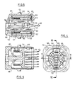
- the disk file shown in Figures 1 and 2 comprises three major sub-assemblies. These are the disk stack subassembly 10, which incorporates an in-hub motor 30, and two linear actuators 50 and 70 of the voice coil type. These subassemblies are mounted on and supported by a box frame casting 80, shown isometrically in Figure 3, which is the major structural component of the file.
- the file is, thus, of essentially modular construction allowing these subassemblies to be pre-assembled and tested before the relatively straightforward operation of bolting them to the box frame.
- a cover 90 is also mounted on the box frame along with several minor, non-structural components.
- the box frame consists of a central box portion 81 which provides the main structural strength. Projecting from an open side of the frame facing the disk stack subassembly 10 are two flange portions 82 and 83. These extend in cantilever fashion above and below the disk stack subassembly to support it by means of a fixed non-rotating spindle 11.
- the flanges 82 and 83 are provided with slots 84 for receiving reduced spindle end portions 12.
- the spindle ends are formed with two parallel flat surfaces provided with cross bores to permit the disk stack subassembly to be rigidly bolted to the box frame flanges 82 and 83 by bolts 13.
- the frame On the opposite side of the box frame 80, the frame is closed except for two large window apertures, 85 and 86, for receiving the linear actuators 50 and 60. These are bolted through mounting flanges 51, 61 against complementary faces, 87, 88, of the box frame from which they are spaced by an O-ring seal 52.
- the frame also supports a filter assembly 91 for removing contamination from the sealed file enclosure formed by cover 90, box frame 80 and actuators 50 and 60
- a printed circuit board 92, carrying a Hall effect sensor for detecting the rotational position of the motor is also mounted on the box frame.
- the cover 90 which is of thin sheet metal, is mounted in the groove of a rubber sealing strip 94 around the periphery of full box portion 81 of the frame.
- the disk stack subassembly 10 comprises a hub 15 mounted for rotation about the spindle 11 by bearings 16 and 17. Axial movement of the hub is opposed by a Belleville washer providing an axial preload. Externally the hub carries a stack of seven magnetic disks 18, separated by spacer rings. The disk stack is clamped to the hub by means of a sprung clamp ring 19. The lower surface of the hub carries a ring magnet 20 for activating the Hall sensor on circuit board 92.
- the hub carries a cylindrical multipole permanent bar magnet 31 which form the rotor of the brushless DC motor 30.
- the motor is driven by a motor drive circuit to rotate the disks 18 past air bearing transducer heads 40.
- the heads are mounted by means of leaf spring flexures 41 on head support arm portions 53 ( Figure 2) of the actuator carriage 54.
- the flexures bias the heads into air bearing contact with the rotating disks.
- the heads 40 carried by flexures 41 serve only the lower surfaces of disks 18.
- a similar set of heads (not shown) is mounted in inverted fashion on the carriage of actuator 70 to serve the upper surfaces of disks 18.
- the carriage 54 includes, as has been stated, a number of head support arm portions 53. These project from a vertical bar 55 which spans a cylindrical coil former 56 carrying a voice coil 57.
- a central beam 58 of cruciform section projects rearwardly from the centre of bar 55 and is provided with sets of wheels 59, 60 and 61 mounted on stub shafts set into the beam.
- the sets of wheels 59 and 60 run on a fixed cylindrical guide rod 52 while the wheels 61 run on a second parallel guide rod 63 to permit the carriage to move radially towards and away from the axis of rotation of the disk stack subassembly 10.
- the voice coil 57 and former 56 are located on a gap of substantially annular cross section between radially magnetised permanent magnet sections 64 and circumferentially divided inner pole pieces 65.
- the magnetic circuit between magnets 64 and pole pieces 65 is completed by the actuator housing and by a flux return plate 66 (removed in Figure 4).
- the flux return plate also serves to shield the disks from stray magnetic fields emanating from the permanent magnets but is, of course, slotted to enable passage of the heads 40 and their support arm structure.
- two rubber rings 67 formed with protuberances to act as end stops are provided at the ends of the flux gap.
- a final component of the actuator is a copper sleeve 69 lining the permanent magnetic flux gap and completely surrounding the moving carriage.
- the sleeve 69 forms a shorted turn around the voice coil to reduce the current rise time of the coil.
- the heat generated in the drive motor 30 and in actuators 50 and 70 establishes temperature gradients which can cause distortion or bending of the structure due to differential thermal expansion.
- the flow of heat is symmetrical so that the temperature pattern existing at the top of the file will be the same as that at the bottom.
- the structure is symmetrical so that, providing the temperature distribution is also symmetrical, then no distortion will be induced.
- the structure as has been described, is much more rigid so that any residual thermal stresses will produce a smaller movement than in the conventional structure.
- the symmetry of the design ensures that any distortion will not produce inter-head misregistration but rather other forms of bending, since any distortion of the top half of the structure will compensate for the equal but opposite distortion of the bottom half.
- the design symmetry and structural rigidity also helps to resist transient misregistration caused by vibrations emanating from the actuators or drive motor. Again, the effects on the spindle ends will tend to minimise out-of-plane modes of vibration.
- the modularity of the design allows separate assembly and testing of the disk stack and actuator subassemblies. Because the disk stack subassembly includes motor and bearings and can be easily supported by means of the fixed spindle ends 12, it is possible to perform such operations as surface analysis testing and servowriting prior to final assembly. This permits faulty subassemblies to be identified and reworked without the need to disassemble or reject the whole file.
- FIG. 1 Another aspect of the design of the file of Figures 1 to 6 is the use of dual actuators 50 and 70 whose associated heads 40 serve the lower and upper surfaces of the disks 18 respectively.
- FIG. 2 has seven disks.
- Figure 7 there is shown a single actuator version of a disk file according to the invention which has only five disks 118 in the same height. This is because additional space must be allowed between disks 118 for both heads on flexures 141 serving the lower surface of the disks 118 and additional heads 142 on flexures 143 serving the upper surfaces of the disks.
- the construction of the disk file of Figure 7 is substantially identical to that of the file of Figures 1 to 6 and, thus, will not be described.
- the actuator 150 is mounted on the X-X plane of symmetry (compare Figure 2) and the file of Figure 7 thus has all the advantages of symmetry and ruggedness of the file of Figures 1 to 6.
Landscapes
- Moving Of Heads (AREA)
- Vehicle Body Suspensions (AREA)
- Automatic Disk Changers (AREA)
Priority Applications (6)
| Application Number | Priority Date | Filing Date | Title |
|---|---|---|---|
| EP85307881A EP0222939B1 (fr) | 1985-10-31 | 1985-10-31 | Mémoire à disques avec moteur intégré dans le moyeu de la pile de disques |
| DE8585307881T DE3581544D1 (de) | 1985-10-31 | 1985-10-31 | Plattenspeicher mit einem in die nabe des plattenstapels integrierten antriebsmotor. |
| JP61230239A JPS62112284A (ja) | 1985-10-31 | 1986-09-30 | デイスク・フアイル装置 |
| US06/918,184 US4743995A (en) | 1985-10-31 | 1986-10-14 | Disk file with in-hub motor |
| CA000521177A CA1282492C (fr) | 1985-10-31 | 1986-10-22 | Lecteur de disques a moteur incorpore au moyeu |
| BR8605304A BR8605304A (pt) | 1985-10-31 | 1986-10-29 | Arquivo de discos |
Applications Claiming Priority (1)
| Application Number | Priority Date | Filing Date | Title |
|---|---|---|---|
| EP85307881A EP0222939B1 (fr) | 1985-10-31 | 1985-10-31 | Mémoire à disques avec moteur intégré dans le moyeu de la pile de disques |
Publications (2)
| Publication Number | Publication Date |
|---|---|
| EP0222939A1 true EP0222939A1 (fr) | 1987-05-27 |
| EP0222939B1 EP0222939B1 (fr) | 1991-01-23 |
Family
ID=8194419
Family Applications (1)
| Application Number | Title | Priority Date | Filing Date |
|---|---|---|---|
| EP85307881A Expired EP0222939B1 (fr) | 1985-10-31 | 1985-10-31 | Mémoire à disques avec moteur intégré dans le moyeu de la pile de disques |
Country Status (6)
| Country | Link |
|---|---|
| US (1) | US4743995A (fr) |
| EP (1) | EP0222939B1 (fr) |
| JP (1) | JPS62112284A (fr) |
| BR (1) | BR8605304A (fr) |
| CA (1) | CA1282492C (fr) |
| DE (1) | DE3581544D1 (fr) |
Cited By (6)
| Publication number | Priority date | Publication date | Assignee | Title |
|---|---|---|---|---|
| EP0307136A2 (fr) * | 1987-09-08 | 1989-03-15 | International Business Machines Corporation | Mémoire à disques comportant un sous-ensemble de pile de disques et méthode d'assemblage |
| EP0362285A4 (fr) * | 1987-05-29 | 1990-03-28 | Conner Peripherals Inc | Architecture d'unite d'entrainement de disquettes. |
| EP0361783A2 (fr) * | 1988-09-27 | 1990-04-04 | International Business Machines Corporation | Mémoire à disques avec boîtier symétrique |
| EP0381368A2 (fr) * | 1989-01-30 | 1990-08-08 | International Business Machines Corporation | Entrainement de disque rigide avec un axe en sécurité |
| EP0381407A1 (fr) * | 1989-01-31 | 1990-08-08 | International Business Machines Corporation | Unité de disque magnétique |
| EP0428290A2 (fr) * | 1989-11-13 | 1991-05-22 | Hewlett-Packard Company | Mécanisme d'entraînement à disque à comportement thermique prévisible |
Families Citing this family (20)
| Publication number | Priority date | Publication date | Assignee | Title |
|---|---|---|---|---|
| USRE38662E1 (en) | 1980-05-10 | 2004-11-30 | Papst Licensing Gmbh & Co. Kg | Disk storage device having a sealed bearing tube |
| USRE37058E1 (en) | 1980-05-10 | 2001-02-20 | Papst Licensing Gmbh & Co. Kg | Disk storage device having contamination seals |
| USRE38673E1 (en) | 1980-05-10 | 2004-12-21 | Papst Licensing Gmbh & Co. Kg | Disk storage device having a hub sealing member feature |
| USRE38601E1 (en) | 1980-05-10 | 2004-09-28 | Papst Licensing, GmbH & Co. KG | Disk storage device having a radial magnetic yoke feature |
| JP2718670B2 (ja) * | 1986-11-17 | 1998-02-25 | 株式会社日立製作所 | 磁気デイスク装置 |
| JPH0770183B2 (ja) * | 1987-03-30 | 1995-07-31 | 株式会社東芝 | 磁気ディスク装置 |
| JPH0291871A (ja) * | 1988-09-28 | 1990-03-30 | Fujitsu Ltd | ディスクファイル装置 |
| US5157295A (en) * | 1989-01-25 | 1992-10-20 | Conner Peripherals, Inc. | Under-the-hub disk drive spin motor |
| DE68920322T2 (de) * | 1989-03-15 | 1995-07-06 | Ibm | Magnetkopf-positioniereinrichtung. |
| JP2693840B2 (ja) * | 1989-12-19 | 1997-12-24 | 富士通株式会社 | 磁気ディスク装置 |
| US5148338A (en) * | 1990-11-14 | 1992-09-15 | Digital Equipment Corporation | Disk drive spindle hub assembly |
| JPH04270842A (ja) * | 1991-02-05 | 1992-09-28 | Mitsubishi Electric Corp | 空調換気装置 |
| DE4221281A1 (de) * | 1991-06-29 | 1993-01-07 | Papst Motoren Gmbh & Co Kg | Plattenspeicherantrieb |
| US5400196A (en) * | 1992-04-30 | 1995-03-21 | International Business Machines Corporation | DASD with spindle imbalance isolation and method for producing same |
| US5341351A (en) * | 1992-10-08 | 1994-08-23 | International Business Machines Corporation | Method and means for optimally accessing data residing on dual actuator DASDs |
| JP4427866B2 (ja) * | 1999-12-17 | 2010-03-10 | アイシン・エィ・ダブリュ株式会社 | モータ |
| CN1319068C (zh) * | 2002-11-25 | 2007-05-30 | 新科实业有限公司 | 硬盘驱动器装置和装配硬盘驱动器装置的方法 |
| US20090180214A1 (en) * | 2008-01-10 | 2009-07-16 | Erik Solhjell | Tape cartridge with built-in reel motors |
| ES2395222T3 (es) * | 2008-01-12 | 2013-02-11 | Linak A/S | Dispositivo de accionamiento lineal |
| US8476794B2 (en) * | 2009-05-27 | 2013-07-02 | Empire Technology Development Llc | Wheel motor with rotating outer rotor |
Citations (7)
| Publication number | Priority date | Publication date | Assignee | Title |
|---|---|---|---|---|
| FR2306503A1 (fr) * | 1975-04-02 | 1976-10-29 | Ibm | Systeme de purification de gaz pour memoire a disques magnetiques |
| US4005490A (en) * | 1975-05-15 | 1977-01-25 | Sperry Rand Corporation | Magnetic disc memory |
| GB2005454A (en) * | 1977-09-30 | 1979-04-19 | Ibm | Magnetic-Disk files |
| EP0014231A1 (fr) * | 1979-01-25 | 1980-08-20 | International Business Machines Corporation | Appareil pour l'emmagasinage d'informations |
| EP0063607A1 (fr) * | 1980-10-29 | 1982-11-03 | Fujitsu Limited | Unite de disques magnetiques |
| EP0064731A1 (fr) * | 1981-05-07 | 1982-11-17 | Siemens Aktiengesellschaft | Cassette à disques pour appareil d'enregistrement de données |
| EP0151260A1 (fr) * | 1984-02-07 | 1985-08-14 | Siemens Aktiengesellschaft | Mémoire à disques magnétiques comprenant une pile de disques sur paliers latéraux à l'intérieur d'un boîtier étant élastique en partie |
Family Cites Families (1)
| Publication number | Priority date | Publication date | Assignee | Title |
|---|---|---|---|---|
| DE3404241A1 (de) * | 1984-02-07 | 1985-08-08 | Siemens AG, 1000 Berlin und 8000 München | Geteiltes gehaeuse fuer einen magnetplattenspeicher mit umlaufendem dichtungsring |
-
1985
- 1985-10-31 DE DE8585307881T patent/DE3581544D1/de not_active Expired - Fee Related
- 1985-10-31 EP EP85307881A patent/EP0222939B1/fr not_active Expired
-
1986
- 1986-09-30 JP JP61230239A patent/JPS62112284A/ja active Granted
- 1986-10-14 US US06/918,184 patent/US4743995A/en not_active Expired - Fee Related
- 1986-10-22 CA CA000521177A patent/CA1282492C/fr not_active Expired - Fee Related
- 1986-10-29 BR BR8605304A patent/BR8605304A/pt not_active IP Right Cessation
Patent Citations (7)
| Publication number | Priority date | Publication date | Assignee | Title |
|---|---|---|---|---|
| FR2306503A1 (fr) * | 1975-04-02 | 1976-10-29 | Ibm | Systeme de purification de gaz pour memoire a disques magnetiques |
| US4005490A (en) * | 1975-05-15 | 1977-01-25 | Sperry Rand Corporation | Magnetic disc memory |
| GB2005454A (en) * | 1977-09-30 | 1979-04-19 | Ibm | Magnetic-Disk files |
| EP0014231A1 (fr) * | 1979-01-25 | 1980-08-20 | International Business Machines Corporation | Appareil pour l'emmagasinage d'informations |
| EP0063607A1 (fr) * | 1980-10-29 | 1982-11-03 | Fujitsu Limited | Unite de disques magnetiques |
| EP0064731A1 (fr) * | 1981-05-07 | 1982-11-17 | Siemens Aktiengesellschaft | Cassette à disques pour appareil d'enregistrement de données |
| EP0151260A1 (fr) * | 1984-02-07 | 1985-08-14 | Siemens Aktiengesellschaft | Mémoire à disques magnétiques comprenant une pile de disques sur paliers latéraux à l'intérieur d'un boîtier étant élastique en partie |
Non-Patent Citations (2)
| Title |
|---|
| PATENT ABSTRACTS OF JAPAN, vol. 6, no. 59 (P-110)[937], 16th April 1982; & JP - A - 56 169 271 (FUJITSU) 25-12-1981 * |
| PATENT ABSTRACTS OF JAPAN, vol. 7, no. 245 (P-233)[1390], 29th October 1983; & JP - A - 58 130 468 (NIPPON DENKI K.K.) 03-08-1983 * |
Cited By (12)
| Publication number | Priority date | Publication date | Assignee | Title |
|---|---|---|---|---|
| EP0362285A4 (fr) * | 1987-05-29 | 1990-03-28 | Conner Peripherals Inc | Architecture d'unite d'entrainement de disquettes. |
| EP0362285A1 (fr) * | 1987-05-29 | 1990-04-11 | Conner Peripherals Inc | Architecture d'unite d'entrainement de disquettes. |
| EP0307136A2 (fr) * | 1987-09-08 | 1989-03-15 | International Business Machines Corporation | Mémoire à disques comportant un sous-ensemble de pile de disques et méthode d'assemblage |
| US4835637A (en) * | 1987-09-08 | 1989-05-30 | International Business Machines Corporation | Disk file with in-hub motor |
| EP0307136A3 (en) * | 1987-09-08 | 1989-11-02 | International Business Machines Corporation | Disk file including disk stack subassembly and method of assembly thereof |
| EP0361783A2 (fr) * | 1988-09-27 | 1990-04-04 | International Business Machines Corporation | Mémoire à disques avec boîtier symétrique |
| EP0361783A3 (fr) * | 1988-09-27 | 1991-03-06 | International Business Machines Corporation | Mémoire à disques avec boítier symétrique |
| EP0381368A2 (fr) * | 1989-01-30 | 1990-08-08 | International Business Machines Corporation | Entrainement de disque rigide avec un axe en sécurité |
| EP0381368A3 (fr) * | 1989-01-30 | 1991-05-29 | International Business Machines Corporation | Entrainement de disque rigide avec un axe en sécurité |
| EP0381407A1 (fr) * | 1989-01-31 | 1990-08-08 | International Business Machines Corporation | Unité de disque magnétique |
| EP0428290A2 (fr) * | 1989-11-13 | 1991-05-22 | Hewlett-Packard Company | Mécanisme d'entraînement à disque à comportement thermique prévisible |
| EP0428290A3 (en) * | 1989-11-13 | 1992-01-15 | Hewlett-Packard Company | Thermally predictable disk drive mechanism |
Also Published As
| Publication number | Publication date |
|---|---|
| US4743995A (en) | 1988-05-10 |
| JPS62112284A (ja) | 1987-05-23 |
| JPH0241101B2 (fr) | 1990-09-14 |
| DE3581544D1 (de) | 1991-02-28 |
| EP0222939B1 (fr) | 1991-01-23 |
| BR8605304A (pt) | 1987-07-28 |
| CA1282492C (fr) | 1991-04-02 |
Similar Documents
| Publication | Publication Date | Title |
|---|---|---|
| EP0222939B1 (fr) | Mémoire à disques avec moteur intégré dans le moyeu de la pile de disques | |
| JP2559138Y2 (ja) | スピンドルモータ組立体 | |
| US4544972A (en) | Swinging actuators for use in magnetic disc type memory devices | |
| US6115215A (en) | Balanced actuator which accesses separate disc assemblies | |
| US5801901A (en) | Disc drive clamp fastener including a clamp disc indentation | |
| US4490635A (en) | Pure torque, limited displacement transducer | |
| EP0417110B1 (fr) | Procede d'assemblage d'une unite de disques | |
| EP0307136B1 (fr) | Mémoire à disques comportant un sous-ensemble de pile de disques et méthode d'assemblage | |
| JPS6120073B2 (fr) | ||
| US5016238A (en) | Linear actuator for radial access in disk recorder/player | |
| JPS5835030B2 (ja) | 並列コイル型作動装置 | |
| KR0150438B1 (ko) | 선형 액츄에이터를 갖는 디스크 드라이브 | |
| US4974104A (en) | Linear actuator disk file with symmetric housing | |
| US4263629A (en) | Disk file with symmetrical hollow base | |
| US4751597A (en) | Center of percussion head actuator assembly | |
| IE47039B1 (en) | Disk file with enclosure wall base | |
| US6498407B1 (en) | Low speed moving magnet motor having a high inertia rotor | |
| US7155807B2 (en) | Method of centering media disks on the hub of a spindle motor in a hard disk drive | |
| US7283325B2 (en) | Apparatus and system for centering media disks on the hub of a spindle motor in a hard disk drive | |
| JP2948041B2 (ja) | 回転式アーム・アクチュエータ | |
| JPH0291871A (ja) | ディスクファイル装置 | |
| JPH0395765A (ja) | 磁気ディスク装置 | |
| JPH11215791A (ja) | 回転駆動装置 | |
| JPH04355654A (ja) | ボイスコイルモータ | |
| JPH0366085A (ja) | ディスク駆動装置 |
Legal Events
| Date | Code | Title | Description |
|---|---|---|---|
| PUAI | Public reference made under article 153(3) epc to a published international application that has entered the european phase |
Free format text: ORIGINAL CODE: 0009012 |
|
| AK | Designated contracting states |
Kind code of ref document: A1 Designated state(s): BE CH DE FR GB IT LI NL SE |
|
| 17P | Request for examination filed |
Effective date: 19870821 |
|
| 17Q | First examination report despatched |
Effective date: 19890303 |
|
| GRAA | (expected) grant |
Free format text: ORIGINAL CODE: 0009210 |
|
| AK | Designated contracting states |
Kind code of ref document: B1 Designated state(s): BE CH DE FR GB IT LI NL SE |
|
| REF | Corresponds to: |
Ref document number: 3581544 Country of ref document: DE Date of ref document: 19910228 |
|
| ET | Fr: translation filed | ||
| ITF | It: translation for a ep patent filed |
Owner name: IBM - DR. ARRABITO MICHELANGELO |
|
| PLBE | No opposition filed within time limit |
Free format text: ORIGINAL CODE: 0009261 |
|
| STAA | Information on the status of an ep patent application or granted ep patent |
Free format text: STATUS: NO OPPOSITION FILED WITHIN TIME LIMIT |
|
| 26N | No opposition filed | ||
| EAL | Se: european patent in force in sweden |
Ref document number: 85307881.4 |
|
| PGFP | Annual fee paid to national office [announced via postgrant information from national office to epo] |
Ref country code: GB Payment date: 19950926 Year of fee payment: 11 |
|
| PGFP | Annual fee paid to national office [announced via postgrant information from national office to epo] |
Ref country code: SE Payment date: 19951002 Year of fee payment: 11 |
|
| PGFP | Annual fee paid to national office [announced via postgrant information from national office to epo] |
Ref country code: FR Payment date: 19951009 Year of fee payment: 11 |
|
| PGFP | Annual fee paid to national office [announced via postgrant information from national office to epo] |
Ref country code: BE Payment date: 19951023 Year of fee payment: 11 |
|
| PGFP | Annual fee paid to national office [announced via postgrant information from national office to epo] |
Ref country code: DE Payment date: 19951030 Year of fee payment: 11 |
|
| PGFP | Annual fee paid to national office [announced via postgrant information from national office to epo] |
Ref country code: NL Payment date: 19951031 Year of fee payment: 11 |
|
| PGFP | Annual fee paid to national office [announced via postgrant information from national office to epo] |
Ref country code: CH Payment date: 19960201 Year of fee payment: 11 |
|
| PG25 | Lapsed in a contracting state [announced via postgrant information from national office to epo] |
Ref country code: LI Effective date: 19961031 Ref country code: GB Effective date: 19961031 Ref country code: CH Effective date: 19961031 Ref country code: BE Effective date: 19961031 |
|
| PG25 | Lapsed in a contracting state [announced via postgrant information from national office to epo] |
Ref country code: SE Effective date: 19961101 |
|
| BERE | Be: lapsed |
Owner name: INTERNATIONAL BUSINESS MACHINES CORP. Effective date: 19961031 |
|
| PG25 | Lapsed in a contracting state [announced via postgrant information from national office to epo] |
Ref country code: NL Effective date: 19970501 |
|
| REG | Reference to a national code |
Ref country code: CH Ref legal event code: PL |
|
| GBPC | Gb: european patent ceased through non-payment of renewal fee |
Effective date: 19961031 |
|
| PG25 | Lapsed in a contracting state [announced via postgrant information from national office to epo] |
Ref country code: FR Effective date: 19970630 |
|
| NLV4 | Nl: lapsed or anulled due to non-payment of the annual fee |
Effective date: 19970501 |
|
| PG25 | Lapsed in a contracting state [announced via postgrant information from national office to epo] |
Ref country code: DE Effective date: 19970701 |
|
| EUG | Se: european patent has lapsed |
Ref document number: 85307881.4 |
|
| REG | Reference to a national code |
Ref country code: FR Ref legal event code: ST |