EP0222741B1 - Thickness measurement device for foil material - Google Patents
Thickness measurement device for foil material Download PDFInfo
- Publication number
- EP0222741B1 EP0222741B1 EP85902030A EP85902030A EP0222741B1 EP 0222741 B1 EP0222741 B1 EP 0222741B1 EP 85902030 A EP85902030 A EP 85902030A EP 85902030 A EP85902030 A EP 85902030A EP 0222741 B1 EP0222741 B1 EP 0222741B1
- Authority
- EP
- European Patent Office
- Prior art keywords
- force
- measuring
- release
- spring
- measuring gap
- Prior art date
- Legal status (The legal status is an assumption and is not a legal conclusion. Google has not performed a legal analysis and makes no representation as to the accuracy of the status listed.)
- Expired
Links
- 238000005259 measurement Methods 0.000 title claims abstract description 13
- 239000000463 material Substances 0.000 title abstract description 27
- 239000011888 foil Substances 0.000 title abstract 2
- 230000001419 dependent effect Effects 0.000 claims description 4
- 230000007246 mechanism Effects 0.000 abstract description 4
- 238000012360 testing method Methods 0.000 description 22
- 229910000831 Steel Inorganic materials 0.000 description 8
- 239000010959 steel Substances 0.000 description 8
- 230000000903 blocking effect Effects 0.000 description 6
- 230000015572 biosynthetic process Effects 0.000 description 4
- 239000013078 crystal Substances 0.000 description 3
- 208000027744 congestion Diseases 0.000 description 2
- 230000001960 triggered effect Effects 0.000 description 2
- 230000005856 abnormality Effects 0.000 description 1
- 230000006978 adaptation Effects 0.000 description 1
- 230000008859 change Effects 0.000 description 1
- 239000011093 chipboard Substances 0.000 description 1
- 230000008878 coupling Effects 0.000 description 1
- 238000010168 coupling process Methods 0.000 description 1
- 238000005859 coupling reaction Methods 0.000 description 1
- 238000001514 detection method Methods 0.000 description 1
- 238000011161 development Methods 0.000 description 1
- 238000011156 evaluation Methods 0.000 description 1
- 230000007257 malfunction Effects 0.000 description 1
- 238000000034 method Methods 0.000 description 1
- 239000000123 paper Substances 0.000 description 1
- 230000008569 process Effects 0.000 description 1
- 230000001681 protective effect Effects 0.000 description 1
- 239000010453 quartz Substances 0.000 description 1
- VYPSYNLAJGMNEJ-UHFFFAOYSA-N silicon dioxide Inorganic materials O=[Si]=O VYPSYNLAJGMNEJ-UHFFFAOYSA-N 0.000 description 1
- 230000003068 static effect Effects 0.000 description 1
Images

Classifications
-
- G—PHYSICS
- G01—MEASURING; TESTING
- G01B—MEASURING LENGTH, THICKNESS OR SIMILAR LINEAR DIMENSIONS; MEASURING ANGLES; MEASURING AREAS; MEASURING IRREGULARITIES OF SURFACES OR CONTOURS
- G01B21/00—Measuring arrangements or details thereof, where the measuring technique is not covered by the other groups of this subclass, unspecified or not relevant
- G01B21/02—Measuring arrangements or details thereof, where the measuring technique is not covered by the other groups of this subclass, unspecified or not relevant for measuring length, width, or thickness
- G01B21/08—Measuring arrangements or details thereof, where the measuring technique is not covered by the other groups of this subclass, unspecified or not relevant for measuring length, width, or thickness for measuring thickness
-
- G—PHYSICS
- G01—MEASURING; TESTING
- G01B—MEASURING LENGTH, THICKNESS OR SIMILAR LINEAR DIMENSIONS; MEASURING ANGLES; MEASURING AREAS; MEASURING IRREGULARITIES OF SURFACES OR CONTOURS
- G01B5/00—Measuring arrangements characterised by the use of mechanical techniques
- G01B5/02—Measuring arrangements characterised by the use of mechanical techniques for measuring length, width or thickness
- G01B5/06—Measuring arrangements characterised by the use of mechanical techniques for measuring length, width or thickness for measuring thickness
- G01B5/068—Measuring arrangements characterised by the use of mechanical techniques for measuring length, width or thickness for measuring thickness of objects while moving
-
- G—PHYSICS
- G01—MEASURING; TESTING
- G01B—MEASURING LENGTH, THICKNESS OR SIMILAR LINEAR DIMENSIONS; MEASURING ANGLES; MEASURING AREAS; MEASURING IRREGULARITIES OF SURFACES OR CONTOURS
- G01B7/00—Measuring arrangements characterised by the use of electric or magnetic techniques
- G01B7/02—Measuring arrangements characterised by the use of electric or magnetic techniques for measuring length, width or thickness
- G01B7/06—Measuring arrangements characterised by the use of electric or magnetic techniques for measuring length, width or thickness for measuring thickness
- G01B7/063—Measuring arrangements characterised by the use of electric or magnetic techniques for measuring length, width or thickness for measuring thickness using piezoelectric resonators
-
- G—PHYSICS
- G07—CHECKING-DEVICES
- G07D—HANDLING OF COINS OR VALUABLE PAPERS, e.g. TESTING, SORTING BY DENOMINATIONS, COUNTING, DISPENSING, CHANGING OR DEPOSITING
- G07D7/00—Testing specially adapted to determine the identity or genuineness of valuable papers or for segregating those which are unacceptable, e.g. banknotes that are alien to a currency
- G07D7/16—Testing the dimensions
- G07D7/164—Thickness
-
- G—PHYSICS
- G07—CHECKING-DEVICES
- G07D—HANDLING OF COINS OR VALUABLE PAPERS, e.g. TESTING, SORTING BY DENOMINATIONS, COUNTING, DISPENSING, CHANGING OR DEPOSITING
- G07D7/00—Testing specially adapted to determine the identity or genuineness of valuable papers or for segregating those which are unacceptable, e.g. banknotes that are alien to a currency
- G07D7/181—Testing mechanical properties or condition, e.g. wear or tear
- G07D7/183—Detecting folds or doubles
Definitions
- Device for the contacting measurement of thickness differences on sheet material which is fed to the device with the aid of a transport system, with a measuring gap provided in the transport plane, which by means of an abutment rigidly arranged with respect to the measuring gap and a first deflectable perpendicular to the sheet material in relation to the measuring gap Scanning element is formed.
- a thickness measuring device for the mechanical thickness measurement of chipboard is known. Differences in the thickness of the material to be measured are measured in a measuring gap between a sensor in the form of a scanning roller and a rigid plate support.
- the scanning roller is connected to a rod which is guided in a first cylinder piston arrangement (measuring cylinder) so that it can be moved up and down.
- the geometry of the measuring cylinder is designed so that the piston can take up the measuring stroke against an air cushion.
- a second cylinder piston arrangement (adjusting cylinder) is mechanically rigidly coupled to the first, with the task of performing the zero adjustment of the device or adjusting the measuring system to the expected thickness "d" of the material to be measured.
- the pressure in the adjusting cylinder is very high compared to that in the measuring cylinder, so that the thickness differences in the tolerance range d ⁇ Ad caused by the material to be measured can be absorbed by the measuring cylinder unaffected by movements of the adjusting cylinder. If excess thicknesses occur in the measuring gap that exceed the tolerances of ⁇ Ad, the permissible working range is exceeded in the measuring cylinder and the forces resulting from the excess thickness are transferred to the cylinder piston arrangement which now acts as a rigid abutment. Since no measures are provided to protect the thickness measuring device against excess thickness, damage or misalignments inevitably occur on the measuring system.
- the contacting thickness measurement is problematic insofar as the necessary measuring speeds are much higher there and the material to be measured is transported through the measuring device in a much faster sequence and the differences in thickness to be measured are significantly smaller.
- Some of these abnormalities are a multiple of the "standard thickness". They easily lead to the formation of jams in the transport system as well as damage or misalignments to the measuring system. Since the malfunctions in most cases have to be remedied manually, the throughput of the document sorting machine may be greatly reduced.
- the invention is therefore based on the object to propose a device for the contact measurement of thickness differences on sheet material, which the above. Avoids disadvantages.
- the basic idea of the invention is to provide a pre-test scanning element in front of the actual measuring gap, which preferably forms a pre-test measuring gap together with the abutment of the first scanning element, the pre-test scanning element reacting to excessive thickness of the transported material and, if necessary, the measuring system the transport level swings away.
- the pre-test sensing element which detects the excess thickness and is even insensitive to mechanical influences, absorbs the forces caused by excess thickness and uses it to swing the measuring system away, so that the formation of jams in the transport system and damage and misalignment of the measuring system are avoided.
- An abutment interacting with the scanning elements is preferably a steel roller, which is also an element of the transport system.
- the pivoting away of the measuring device is only triggered when a certain, adjustable force acts on the pre-test scanning element.
- the pre-test scanning element is connected to a trigger mechanism which rigidly couples the measuring system to the steel roller forming the abutment in the permissible working range.
- the function of the second abutment is canceled when the force acting on the pre-test scanning element exceeds the predetermined force set on the trigger mechanism.
- the trigger mechanism is preferably designed such that the measuring system is automatically returned to the original position as soon as the excess thickness causing the deflection has passed the measuring system. This eliminates the need for manual intervention to eliminate accidents.
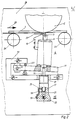
- FIG. 1 shows, in an exemplary embodiment, a thickness measuring device according to the invention.
- the essential elements of the device are the measuring device 4, the triggering device 15, the transport system 24, 25, 3 with integrated abutment 2 and the pre-test scanning element 10.
- the measuring device 4 itself works in principle as described above in connection with DE-PS-3 133 818. Differences in thickness in the material to be measured - in the case of banknotes, for example, in the area of the watermark - thus, against a rigid abutment, cause the mechanical deflection of a scanning element which is spring-loaded perpendicular to the material to be measured. In the measuring system, the path change is converted directly or indirectly into electrical signals proportional to the thickness of the material to be measured. As shown in Fig. 1, the measuring device 4 is connected via a lever 11 in such a pivot point 12 to a holder 13 that, as indicated by the arrow 9, it can be pivoted about this pivot point. The bracket 13 is on a.
- the base plate 28 is screwed on and also serves to receive the release device 15.
- the release device can be axially displaced in the holder according to the arrow 14 shown in FIG. 1 and can be fixed in the holder 13 in any position.
- a steel roller 2 is rotatably mounted on the base plate 28 as an abutment for the measuring device 4.
- the steel roller is also a functional element of the belt 3 and transport rollers 24, 25, shown only schematically in FIG. 1.
- the pre-test scanning element 10 designed as a runner is arranged, which is rigidly connected to the measuring device 4 and the lever 11, forms the pre-test measuring gap 30 with the steel roller 2 and, as is still the case will be explained, cooperates with the trigger device 15 via the lever 11.
- An essential element of the measuring device is the scanning or measuring roller 5, which is connected to a plunger 6.
- the plunger is axially movably supported in the measuring device 4 and connected via a spring 7 to an element 8 which absorbs the force generated by the plunger movement as a result of changes in thickness in the material to be measured and acts on the spring and converts it into an electrical signal.
- a piezo crystal element e.g. quartz crystal force transducer from Kistler, type 9203 can be used as the converter, for example.
- the measuring roller 5 of the measuring device 4 forms, together with the steel roller 2 of the transport system, the measuring gap 22 through which the material to be measured, as shown in FIG. 1, passes in the direction of the arrow 26.
- the setting of the measuring gap between the roller 2 and the measuring roller 5 is carried out by a stop screw 23 provided in the lever II, which is adjustable against the holder 13.
- the measuring gap is adjusted so that even the thinnest point of the material to be expected provides an easily evaluable electrical signal at the piezo crystal.
- the measuring gap 30 of the pre-test scanning element 10 is also set in the exemplary embodiment shown, since this element is rigidly connected to the measuring device.
- the element is attached to the measuring device in such a way that the material to be measured 1 can pass the pre-test measuring gap 30 practically without contact in the intended working area.
- the stopping screw 23 the measuring roller 5 and the pre-test scanning element 10 are fixed to a certain position in the direction of the transport system against the steel roller 2.
- the triggering device 15 fixes the device in the opposite direction.
- the trigger device 15 as shown in FIGS. 1 and 2 in two different working phases, consists in principle of two plungers 16, 18, each of which is movably mounted in a bore 21, 29 of the device 15. While the plunger 16, hereinafter referred to as the thrust plunger, mechanically coupled to the measuring device 4 or to the pre-test scanning element 10 is movably guided in a first bore 21 of the device, the second plunger 18, hereinafter referred to as the locking plunger, slides in one to the first vertically arranged bore 29.
- the push rod 16 has at the end located in the bore 21 a notch 17, in which the locking plunger 18 engages and in which it is held by means of a spring 19, for example a leaf spring.
- Fig. 1 shows the trigger device 15 in the locked state.
- the position of the locking plunger in the bore 29 of the device remains unchanged when a force acts on the push rod 16.
- the locking or release force is essentially dependent on the flank inclination angle of the notch 17, the static friction and the spring force 19 which acts on the locking plunger. If the force exerted on the thrust ram by the material to be measured exceeds the triggering force, the locking ram 18 in the bore 29 is pressed out of the notch 17 against the force of the leaf spring 19. After the locking plunger 18 has been pressed out of the notch 17, it slides on the outer surface of the push plunger (see FIG. 2).
- the tripping time can be adapted to the given conditions by suitable formation of the effective flank length and the spring force.
- the time it takes for the pusher to return to the home position is dependent on the force of the spring 20 and the friction of all of the device elements cooperating in the process.
- all of the functional parameters of the triggering device can be adjusted independently of one another in a simple manner, with which an optimal adaptation to the respective situation is possible.
- the trigger device 15 is rotated into the corresponding thread 31 of the frame 13 until the plunger 16, the measuring device 4 on the measuring roller 5 opposite side just touched without play.
- the measuring device 4 and the pre-test scanning element 10 are quasi rigidly connected by the stop screw 23 on the one hand and by the triggering device 15 on the other hand to the holder 13 fastened on the base plate 23 and thus also to the steel roller 2.
- the strokes of the measuring roller 5 resulting from the thickness differences of the sheet material 1 are converted by the measuring device into tensions proportional to the paper thickness (FIG. 1).
- the triggering force of the triggering device is set such that the forces arising due to the measuring stroke do not sufficiently cancel the blocking effect, so that the triggering device acts as a rigid abutment in the working area of the measuring device.
- This rigid coupling of the measuring device enables the detection and evaluation of even very small strokes, such as occur, for example, when checking the watermark of a banknote.
- Fig. 2 shows the situation in which an accident occurs, such as. B. when transporting a banknote with a Z-fold 27.
- this Z-fold of the banknote represents an excess thickness in relation to the pre-test measuring gap 30 set
- a force acts on the pre-test scanning element 10 against the rigid roller 2, which acts on the housing the measuring device 4 is transmitted to the pushing device 16 to the trigger device 15.
- the blocking force of the triggering device 15 is set, for example, so that the blocking effect is released when a force acts on the pre-test scanning element which is greater than that generated by an excess thickness of 50% of the measured material. If the blocking force is exceeded, as is the case with a Z fold, then the measuring device 4, together with the pre-test scanning element 10, pivots about the pivot point 12 of the lever 11 out of the transport plane. In this phase, contact of the measuring roller 5 with the material 1 to be measured is avoided in order to prevent damage to the measuring system.
- the force of the spring 20 can be chosen to be much smaller than the blocking force necessary to overcome the excess thickness. This means that after overcoming the locking force during the passage in the pre-test measuring gap, the excess thickness is not pressed on with high force. This reduces the risk of congestion in the transport route.
- the tripping time of the blocking effect is chosen to be very short, so that the risk of congestion and the damage or misalignment of the measuring system are additionally effectively prevented.
- the reset time of the device can be set with the force of the spring 20 so "sluggish” that the measuring arrangement only returns to its starting position after complete transport of an "excess thickness", but on the other hand it is again available for testing the next material to be measured .
- the device described ensures reliable and precise thickness testing even with small strokes, that swiveling out of the measuring device prevents the formation of jams in the transport path when an excess thickness occurs from the transport plane, and that the measuring system is protected from damage or misalignments and after an accident, no manual intervention is necessary to remedy it, since the original measurement situation is automatically restored.
Abstract
Description
Vorrichtung für die berührende Messung von Dickenunterschieden an Blattgut, das mit Hilfe eines Transportsystems der Vorrichtung zugeführt wird, mit einem in der Transportebene vorgesehenen Meßsalt, der durch ein in Bezug auf den Meßsalt starr angeordnetes Widerlager und ein bezogen auf den Meßspalt senkrecht zum Blattgut auslenkbares erstes Abtastelement gebildet ist.Device for the contacting measurement of thickness differences on sheet material, which is fed to the device with the aid of a transport system, with a measuring gap provided in the transport plane, which by means of an abutment rigidly arranged with respect to the measuring gap and a first deflectable perpendicular to the sheet material in relation to the measuring gap Scanning element is formed.
Aus der DE-PS-3 133 818 ist eine Dickenmeßvorrichtung für die mechanische Dickenmessung von Spanplatten bekannt. In einem Meßspalt zwischen einem Fühler in Form einer Abtastrolle und einem starren Plattenauflager werden Dickenunterschiede am Meßgut gemessen.From DE-PS-3 133 818 a thickness measuring device for the mechanical thickness measurement of chipboard is known. Differences in the thickness of the material to be measured are measured in a measuring gap between a sensor in the form of a scanning roller and a rigid plate support.
Bei dieser Vorrichtung ist die Abtastrolle mit einer Stange verbunden, die in einer ersten Zylinderkolbenanordnung (Meßzylinder) auf- und niederbewegbar geführt ist. Die Geometrie des Meßzylinders ist so ausgelegt, daß der Kolben gegen ein Luftpolster den Meßhub aufnehmen kann. Eine zweite Zylinderkolbenanordnung (Justierzylinder) ist mechanisch starr mit der ersten gekoppelt, wobei diese die Aufgabe hat, den Nullabgleich der Vorrichtung durchzuführen bzw. das Meßsystem auf die zu erwartende Dicke "d" des Meßgutes einzustellen.In this device, the scanning roller is connected to a rod which is guided in a first cylinder piston arrangement (measuring cylinder) so that it can be moved up and down. The geometry of the measuring cylinder is designed so that the piston can take up the measuring stroke against an air cushion. A second cylinder piston arrangement (adjusting cylinder) is mechanically rigidly coupled to the first, with the task of performing the zero adjustment of the device or adjusting the measuring system to the expected thickness "d" of the material to be measured.
Während der Dickenmessung ist der Druck im Justierzylinder sehr hoch gegenüber dem im Meßzylinder, damit die durch das Meßgut entstehenden Dickenunterschiede im Toleranzbereich d ± Ad unbeeinflußt von Bewegungen des Justierzylinders vom Meßzylinder aufgenommen werden können. Treten im Meßspalt Überdicken auf, die die Toleranzen von ± Ad überschreiten, so wird im Meßzylinder der zulässige Arbeitsbereich überschritten und die durch die Überdicke entstehenden Kräfte auf die nun als starres Widerlager wirkende Zylinderkolbenanordnung übertragen. Da keine Maßnahmen zum Schutz der Dickenmeßvorrichtung gegenüber Überdicken Vorgesehen sind, treten dabei zwangsläufig Beschädigungen bzw. Dejustierungen am Meßsystem auf.During the thickness measurement, the pressure in the adjusting cylinder is very high compared to that in the measuring cylinder, so that the thickness differences in the tolerance range d ± Ad caused by the material to be measured can be absorbed by the measuring cylinder unaffected by movements of the adjusting cylinder. If excess thicknesses occur in the measuring gap that exceed the tolerances of ± Ad, the permissible working range is exceeded in the measuring cylinder and the forces resulting from the excess thickness are transferred to the cylinder piston arrangement which now acts as a rigid abutment. Since no measures are provided to protect the thickness measuring device against excess thickness, damage or misalignments inevitably occur on the measuring system.
Es ist grundsätzlich denkbar, eine Dickenmeßvorrichtung, die nach dem oben geschilderten Prinzip funktioniert, auch bei automatischen Banknoten-Sortieranlagen einzusetzen.It is fundamentally conceivable to use a thickness measuring device, which functions according to the principle described above, also in automatic banknote sorting systems.
Bei einer derartigen Anwendung ist die berührende Dickenmessung aber insofern problematische, weil die notwendigen Meßgeschwindigkeiten dort wesentlich höher sind und das Meßgut in wesentlich schnellerer Folge durch die Meßvorrichtung transportiert wird und die zu messenden Dickenunterschiede wesentlich geringer sind. Dabei ist es in der Praxis nicht zu vermeiden, daß auch übereinanderliegende oder gefaltete Blätter und sogar Fremdteile, wie Heftklammern oder dergleichen, die Dickenmeßvorrichtung passieren. Diese Abnormitäten haben zum Teil ein Mehrfaches der "Normdicke". Sie führen leicht zur Bildung von Staus im Transportsystem sowie zu Beschädigungen bzw. Dejustierungen am Meßsystem. Da die Störungen in den meisten Fällen manuell behoben werden müssen wird der Durchsatz der Beleg-Sortiermaschiene unter Umständen stark reduziert.In such an application, the contacting thickness measurement is problematic insofar as the necessary measuring speeds are much higher there and the material to be measured is transported through the measuring device in a much faster sequence and the differences in thickness to be measured are significantly smaller. In practice, it cannot be avoided that sheets lying on top of one another or folded, and even foreign parts such as staples or the like, pass through the thickness measuring device. Some of these abnormalities are a multiple of the "standard thickness". They easily lead to the formation of jams in the transport system as well as damage or misalignments to the measuring system. Since the malfunctions in most cases have to be remedied manually, the throughput of the document sorting machine may be greatly reduced.
Der Erfindung liegt daher die Aufgabe zugrunde, eine Vorrichtung für die berührende Messung von Dickenunterschieden an Blattgut vorzuschlagen, die die o.g. Nachteile vermeidet.The invention is therefore based on the object to propose a device for the contact measurement of thickness differences on sheet material, which the above. Avoids disadvantages.
Erfindungsgemäß wird die Aufgabe durch die im Hauptanspruch angegebenen Merkmale gelöst.According to the invention the object is achieved by the features specified in the main claim.
Der Grundgedanke der Erfindung besteht darin, vor dem eigentlichen Meßspalt ein Vorprüf-Abtastelement vorzusehen, das vorzugsweise zusammen mit dem Widerlager des ersten Abtastelementes zusammen einen Vorprüf-Meßspalt bildet, wobei das Vorprüf-Abtastelement auf Überdicken des antransportierten Meßgutes reagiert und im Bedarfsfall das Meßsystem aus der Transportebene wegschwenkt. Durch das die Überdicke erfassende und selbst gegen mechanische Einwirkung unempfindliche Vorprüf-Abtastelement werden die durch Überdicken entstehenden Kräfte aufgenommen und zum Wegschwenken des Meßsystem genutzt, so daß die Bildung von Staus im Transportsystem sowie Beschädigungen und Dejustierungen des Meßsystems vermieden werden. Ein mit den Abtastelementen zusammenwirkende Widerlager ist vorzugsweise eine Stahlwalze, die gleichzeitig auch Element des Transportsystems ist.The basic idea of the invention is to provide a pre-test scanning element in front of the actual measuring gap, which preferably forms a pre-test measuring gap together with the abutment of the first scanning element, the pre-test scanning element reacting to excessive thickness of the transported material and, if necessary, the measuring system the transport level swings away. The pre-test sensing element, which detects the excess thickness and is even insensitive to mechanical influences, absorbs the forces caused by excess thickness and uses it to swing the measuring system away, so that the formation of jams in the transport system and damage and misalignment of the measuring system are avoided. An abutment interacting with the scanning elements is preferably a steel roller, which is also an element of the transport system.
Gemäß einer vorteilhaften Weiterbildung der Erfindung wird das Wegschwenken der Meßvorrichtung erst dann ausgelöst, wenn auf das Vorprüf-Abtastelement eine bestimmte, einstellbare Kraft einwirkt. Dazu ist das Vorprüf-Abtastelement mit einem Auslösemechanismus verbunden, der im zulässigen Arbeitsbereich das Meßsystem starr an die das Widerlager bildende Stahlwalze koppelt. Die Funktion des zweiten Widerlagers wird aufgehoben, wenn die auf das Vorprüf-Abtastelement wirkende Kraft die vorgegebene, am Auslösemechanismus eingestellte Kraft überschreitet. Der Auslösemechanismus ist vorzugsweise derart ausgebildet, daß das Meßsystem automatisch in die ursprüngliche Lage zurückversetzt wird, sobald die die Auslenkung verursachende Überdicke das Meßsystem passiert hat. Damit erübrigen sich manuelle Eingriffe zur Beseitigung von Störfällen.According to an advantageous development of the invention, the pivoting away of the measuring device is only triggered when a certain, adjustable force acts on the pre-test scanning element. For this purpose, the pre-test scanning element is connected to a trigger mechanism which rigidly couples the measuring system to the steel roller forming the abutment in the permissible working range. The function of the second abutment is canceled when the force acting on the pre-test scanning element exceeds the predetermined force set on the trigger mechanism. The trigger mechanism is preferably designed such that the measuring system is automatically returned to the original position as soon as the excess thickness causing the deflection has passed the measuring system. This eliminates the need for manual intervention to eliminate accidents.
Weitere Ausführungsformen der Erfindung sind Gegenstand von Unteransprüchen. Weitere Vorteile der Erfindung ergeben sich aus der nachfolgenden Beschreibung eines Ausführungsbeispiels der Erfindung anhand der beigefügten Zeichnung.Further embodiments of the invention are the subject of dependent claims. Further advantages of the invention result from the following description of an embodiment of the invention with reference to the accompanying drawing.
Darin zeigen:
- Fig. 1 eine Dickenmeßvorrichtung in Meßposition zum Messen von Dickenunterschieden an Blattgut,
- Fig. 2 die Schutzposition der Dickenmeßvorrichtung bei Vorliegen von zu dickem Blattgut.
- Fig. 1 shows a thickness measuring device in Measuring position for measuring thickness differences on sheet material,
- Fig. 2 shows the protective position of the thickness measuring device in the presence of too thick sheet material.
Fig. 1 zeigt in einer beispielhaften Ausführungsform eine Dickenmeßvorrichtung gemäß der Erfindung. Die wesentlichen Elemente der Vorrichtung sind die Meßeinrichtung 4, die Auslöseeinrichtung 15, das Transportsystem 24, 25, 3 mit integriertem Widerlager 2 sowie das Vorprüf-Abtastelement 10.1 shows, in an exemplary embodiment, a thickness measuring device according to the invention. The essential elements of the device are the
Die Meßeinrichtung 4 selbst arbeitet prinzipiell so, wie oben im Zusammenhang mit der DE-PS-3 133 818 geschildert. Dickenunterschiede im Meßgut - bei Banknoten beispielsweise im Bereich des Wasserzeichens - bewirken also gegen ein starres Widerlager die mechanische Wegauslenkung eines senkrecht an das Meßgut federnd angelegten Abtastelements. Im Meßsystem wird die Wegänderung direkt oder indirekt in zur Dicke des Meßgutes proportionale elektrische Signale umgesetzt. Wie in Fig. 1 gezeigt, ist die Meßeinrichtung 4 über einen Hebel 11 derart in einem Drehpunkt 12 mit einer Halterung 13 verbunden, daß sie, wie durch den Pfeil 9 angedeutet, um diesen Drehpunkt schwenkbar ist. Die Halterung 13 ist auf einer. Grundplatte 28 aufgeschraubt und dient auch zur Aufnahme der Auslöseeinrichtung 15. Die Auslöseeinrichtung ist in der Halterung entsprechend dem in der Fig. 1 gezeigten Pfeil 14 axial verschiebbar und in jeder beliebigen Position in der Halterung 13 fixierbar. Als Widerlager für die Meßeinrichtung 4 ist auf der Grundplatte 28 eine Stahlwalze 2 drehbar gelagert. Die Stahlwalze ist auch Funktionselement des aus Riemen 3 und Transport rollen 24, 25, in der Fig. 1 lediglich schematisch dargestellten Transportsystems. In Transportrichtung - gekennzeichnet durch den Pfeil 26 vor der Meßeinrichtung ist das als Kufe ausgebildete Vorprüf-Abtastelement 10 angeordnet, das mit der Meßeinrichtung 4 und dem Hebel 11 starr verbunden ist, mit der Stahlwalze 2 den Vorprüf-Meßspalt 30 bildet und, wie noch zu erläutern sein wird, über den Hebel 11 mit der Auslöseeinrichtung 15 zusammenwirkt.The
Wesentliches Element der Meßeinrichtung ist die Abtast- bzw. Meßrolle 5, die mit einem Stößel 6 verbunden ist. Der Stößel ist in der Meßeinrichtung 4 axial beweglich gelagert und über eine Feder 7 mit einem Element 8 verbunden, das die durch die Stößelbewegung infolge von Dickenänderungen im Meßgut erzeugte und auf die Feder wirkende Kraft aufnimmt und in ein elektrisches Signal umwandelt. Als Umsetzer kann beispielsweise ein Piezokristall-Element (z. B. Quarzkristall-Kraftaufnehmer der Firma Kistler, Typ 9203) verwendet werden. Die Meßrolle 5 der Meßeinrichtung 4 bildet zusammen mit der Stahlwalze 2 des Transportsystems den Meßspalt 22, den das Meßgut, wie in der Fig. 1 gezeigt, in Richtung des Pfeils 26 passiert. Die Einstellung des Meßspaltes zwischen der Walze 2 und der Meßrolle 5 wird durch eine im Hebel II vorgesehene Anschlagschraube 23 vorgenommen, die gegen die Halterung 13 verstellbar ist. Durch Verdrehen der Anschlagschraube 23 wird der Meßspalt so eingestellt, daß selbst die dünnste zu erwartende Stelle des Meßgutes ein gut auswertbares elektrisches Signal am Piezokristall liefert. Mit dem Einstellen des Meßspalts 22 ist in dem gezeigten Ausführungsbeispiel auch der Meßspalt 30 des Vorprüf-Abtastelements 10 eingestellt, da dieses Element starr mit der Meßeinrichtung verbunden ist. Das Element wird an der Meßeinrichtung derart befestigt, daß das Meßgut 1 im vorgesehenen Arbeitsbereich den Vorprüf-Meßspalt 30 praktisch ohne Berührung passieren kann. Mit der Anschlagschraube 23 werden die Meßrolle 5 und das Vorprüf-Abtastelement 10 auf eine bestimmte Position in Richtung auf das Transportsystem gegen die Stahlwalze 2 fixiert. Die Fixierung bezüglich der entgegengesetzten Richtung wird durch die Auslöseeinrichtung 15 vorgenommen.An essential element of the measuring device is the scanning or measuring
Die Auslöseeinrichtung 15, wie sie in der Fig. 1 und 2 in zwei unterschiedlichen Arbeitsphasen gezeigt ist, besteht im Prinzip aus zwei Stößeln 16, 18, die in je einer Bohrung 21, 29 der Einrichtung 15 beweglich gelagert sind. Während der mit der Meßeinrichtung 4 bzw. mit dem Vorprüf-Abtastelement 10 mechanisch gekoppelte Stößel 16, im folgenden Schubstößel genannt, in einer ersten Bohrung 21 der Einrichtung beweglich geführt ist, gleitet der zweite Stößel 18, im folgenden Sperrstößel genannt, in einer zur ersten senkrecht angeordneten Bohrung 29. Der Schubstößel 16 weist an dem in der Bohrung 21 befindlichen Ende eine Kerbe 17 auf, in die der Sperrstößel 18 eingreift und in der er mit Hilfe einer Feder 19, beispielsweise einer Blattfeder, gehalten wird.The
Die Fig. 1 zeigt die Auslösevorrichtung 15 im gesperrten Zustand. Bis zu einem bestimmten, einstellbaren Wert bleibt bei einer auf den Schubstößel 16 wirkenden Kraft die Lage des Sperrstößels in der Bohrung 29 der Einrichtung unverändert. Die Sperr- oder Auslösekraft ist im wesentlichen abhängig vom Flanken-Neigungswinkel der Kerbe 17, der Haftreibung und der Federkraft 19, die auf den Sperrstößel wirkt. Übersteigt die auf den Schubstößel vom Meßgut bewirkte Kraft die Auslösekraft, wird der Sperrstößel 18 in der Bohrung 29 gegen die Kraft der Blattfeder 19 aus der Kerbe 17 herausgedrückt. Nachdem der Sperrstoßel 18 aus der Kerbe 17 herausgedrückt wurde, gleitet er auf der Mantelfläche des Schubstößels (siehe dazu Fig. 2). Sobald die auf den Schubstößel wirkende vom Meßgut ausgelöste Kraft verschwindet, wird dieser mit Hilfe einer in der Bohrung 21 angeordneten Feder 20 in die Ausgangsposition, d. h. in die Sperrlage zurückgedrückt. Die Zeit, die vergeht, um den Schubstößel 16 vom gesperrten in den gelösten Zustand zu überführen (Auslösezeit) ist in erster Linie abhängig von dem Weg, den der Sperrstößel 18 auf der Flankenlänge der Kerbe 17 zurücklegt, um aus der Kerbe heraus auf den Schubstößel zu gelangen. Als weitere Parameter gehen die Federkraft der auf den Sperrstößel lastenden Feder 19 sowie Reibungskräfte ein. Die Auslösezeit kann durch geeignete Ausbildung der wirksamen Flankenlänge und der Federkraft den gegebenen Bedingungen angepaßt werden. Schließlich ist die Zeit, die vergeht, um den Schubstößel in die Ausgangsposition zu versetzen, abhängig von der Kraft der Feder 20 und der Reibung aller bei diesem Vorgang zusammenwirkenden Vorrichtungselemente. Wie man erkennt, sind alle Funktionsparameter der Auslöseeinrichtung unabhängig voneinander, auf einfache Weise einstellbar, womit eine optimale Anpassung an die jeweilige Situation möglich ist.Fig. 1 shows the
Nachdem der Meßspalt 22 mit Hilfe der Anschlagschraube 23, wie oben beschrieben, auf die zu messende Dicke des Meßgutes eingestellt ist, wird die Auslöseeinrichtung 15 soweit in das entsprechende Gewinde 31 des Rahmens 13 gedreht, bis der Schubstößel 16 die Meßeinrichtung 4 auf der der Meßrolle 5 gegenüberliegenden Seite gerade spielfrei berührt. Damit sind Meßeinrichtung 4 und Vorprüf-Abtastelement 10 durch die Anschlagschraube 23 einerseits und durch die Auslösevorrichtung 15 andererseits quasi starr mit der auf der Grundplatte 23 befestigten Halterung 13 und damit auch mit der Stahlwalze 2 verbunden.After the measuring
Nach der Erläuterung der einzelnen Funktionselemente soll nachfolgend das Verhalten der Vorrichtung im Meßbetrieb bzw. bei Auftreten eines Störfalls beschrieben werden.After the explanation of the individual functional elements, the behavior of the device in measuring mode or when an accident occurs is described below.
Die durch die Dickenunterschiede des Blattguts 1 entstehenden Hübe der Meßrolle 5 werden durch die Meßeinrichtung in zur Papierdicke proportionale Spannungen umgesetzt (Fig. 1). Die Auslösekraft der Auslöseeinrichtung ist so eingestellt, daß die aufgrund des Meßhubes entstehenden Kräfte nicht ausreichend die Sperrwirkung aufzuheben, so daß die Auslöseeinrichtung im Arbeitsbereich der Meßeinrichtung als starres Widerlager wirkt. Diese starre Kopplung der Meßeinrichtung ermöglicht die Erfassung und Auswertung auch sehr kleiner Hübe, wie sie beispielsweise bei der Prüfung des Wasserzeichens einer Banknote vorkommen. Fig. 2 zeigt die Situation in der ein Störfalle eintritt, wie z. B. beim Antransport einer Banknote mit einer Z-Falte 27. Da diese Z-Falte der Banknote gegenüber dem eingestellten Vorprüf-Meßspalt 30 eine Überdicke darstellt, wirkt auf das Vorprüf-Abtastelement 10 gegen die starre Walze 2 eine Kraft, die über das Gehäuse der Meßeinrichtung 4 auf den Schubstößei 16 zur Auslöseeinrichtung 15 übertragen wird. Die Sperrkraft der Auslöseeinrichtung 15 wird beispielsweise so eingestellt, daß die Sperrwirkung dann aufgehoben wird, wenn auf das Vorprüf-Abtastelement eine Kraft wirkt, die größer ist als die durch eine Überdicke von 50 % des Meßgutes erzeugte. Tritt ein Überschreiten der Sperrkraft ein, wie dies bei einer Z-Falte der Fall ist, so schwenkt die Meßeinrichtung 4 zusammen mit dem Vorprüf-Abtastelement 10 um den Drehpunkt 12 des Hebels 11 aus der Transportebene. In dieser Phase wird die Berührung der Meßrolle 5 mit dem Meßgut 1 vermieden, um Beschädigungen des Meßsystems zu verhindern. Auf die aus der Transportebene weggeschwenkte Anordnung wirkt nun lediglich die durch die Feder 20 erzeugte Kraft, welche nach Freigabe des Meßspaltes 22, 30 die Rückführung der Anordnung in die Ausgangslage ermöglicht. Die Kraft der Feder 20 kann sehr viel kleiner als die zur Überwindung der Überdicke notwendige Sperrkraft gewählt werden. Das bedeutet, daß die Überdicke nach Überwinden der Sperrkraft während des Durchlaufs im Vorprüf-Meßspalt nicht mit hoher Kraft angepreßt wird. Dadurch wird die Gefahr einer Staubildung im Transportweg verringert. Die Auslösezeit der Sperrwirkung, deren Definition oben erläutert wurde, wird sehr kurz gewählt, damit wird die Gefahr Bildung von Staus sowie die Beschädigungen bzw. Dejustierungen des Meßsystems zusätzlich wirkungsvoll verhindert. Die Rückstellzeit der Vorrichtung kann mit der Kraft der Feder 20 derart "träge" eingestellt werden, daß die Meßanordnung zwar erst nach vollständigem Vorbeitransport einer "Überdicke" wieder in ihre Ausgangslage zurückkehrt, daß sie andererseits aber für die Prüfung des nächsten Meßgutes wieder zur Verfügung steht.The strokes of the measuring
Zusammenfassend kann festgestellt werden, daß durch die beispielsweise beschriebene Vorrichtung die sichere und präzise Dickenprüfung auch bei kleinen Hüben gewährleistet ist, daß durch das Ausschwenken der Meßeinrichtung bei Auftreten einer Überdicke aus der Transportebene Staubildung im Transportweg verhindert sowie das Meßsystem vor Beschädigungen bzw. Dejustierungen geschützt ist und nach einem Störfall kein manueller Eingriff zu dessen Behebung notwendig ist, da die ursprüngliche Meßsituation automatisch wiederhergestellt wird.In summary, it can be stated that the device described, for example, ensures reliable and precise thickness testing even with small strokes, that swiveling out of the measuring device prevents the formation of jams in the transport path when an excess thickness occurs from the transport plane, and that the measuring system is protected from damage or misalignments and after an accident, no manual intervention is necessary to remedy it, since the original measurement situation is automatically restored.
Claims (16)
Priority Applications (1)
| Application Number | Priority Date | Filing Date | Title |
|---|---|---|---|
| AT85902030T ATE35860T1 (en) | 1985-04-19 | 1985-04-19 | THICKNESS MEASUREMENT DEVICE FOR SHEET. |
Applications Claiming Priority (1)
| Application Number | Priority Date | Filing Date | Title |
|---|---|---|---|
| PCT/EP1985/000178 WO1986006471A1 (en) | 1985-04-19 | 1985-04-19 | Thickness measurement device for foil material |
Publications (2)
| Publication Number | Publication Date |
|---|---|
| EP0222741A1 EP0222741A1 (en) | 1987-05-27 |
| EP0222741B1 true EP0222741B1 (en) | 1988-07-20 |
Family
ID=8165026
Family Applications (1)
| Application Number | Title | Priority Date | Filing Date |
|---|---|---|---|
| EP85902030A Expired EP0222741B1 (en) | 1985-04-19 | 1985-04-19 | Thickness measurement device for foil material |
Country Status (5)
| Country | Link |
|---|---|
| US (1) | US4777729A (en) |
| EP (1) | EP0222741B1 (en) |
| JP (1) | JPS63501817A (en) |
| DE (1) | DE3563876D1 (en) |
| WO (1) | WO1986006471A1 (en) |
Cited By (4)
| Publication number | Priority date | Publication date | Assignee | Title |
|---|---|---|---|---|
| DE10345064A1 (en) * | 2003-09-26 | 2005-04-14 | Giesecke & Devrient Gmbh | Sheet material thickness measurement device, especially for measuring banknote thickness, has two rigidly mounted rollers, through which material passes, with one of rollers elastically deformed by material |
| DE102004030618A1 (en) * | 2004-06-24 | 2006-01-26 | Giesecke & Devrient Gmbh | Measuring device for measuring the thickness of sheet material like bank-notes has a multitrack thickness sensor with two opposing fixed shafts driven synchronously |
| DE102004045170A1 (en) * | 2004-09-17 | 2006-03-23 | Giesecke & Devrient Gmbh | Banknote thickness measuring method for banknote processing machine, involves summing forces measured at axle ends of one elastic roller, and determining thickness of banknotes and/or variation in thickness of banknotes from summed forces |
| DE102010001825A1 (en) * | 2010-02-11 | 2011-08-11 | FRIMO Group GmbH, 49504 | Device for determining thickness of workpiece i.e. covering film, utilized for airbag flap of motor vehicle, has measuring unit cooperating with probe element for determining thickness of workpiece in area of weakening of workpiece |
Families Citing this family (14)
| Publication number | Priority date | Publication date | Assignee | Title |
|---|---|---|---|---|
| DE3936563A1 (en) * | 1989-11-03 | 1991-05-08 | Kolbus Gmbh & Co Kg | Monitoring arrangement for printer paper - detects missing, detective or multiple sheets from tilt angle of clamping gripper at defined gripping drum positions |
| US5042790A (en) * | 1990-02-16 | 1991-08-27 | Xerox Corporation | Toggled switch for use in a sheet feed apparatus |
| AT395116B (en) * | 1991-03-11 | 1992-09-25 | Andritz Patentverwaltung | METHOD AND DEVICE FOR DETECTING AND ELIMINATING BULBS OF MATERIAL RAILS |
| US5203555A (en) * | 1992-09-04 | 1993-04-20 | Pitney Bowes Inc. | Adjustable dampening device in an apparatus for detecting double fed sheets |
| GB9308803D0 (en) * | 1993-04-28 | 1993-06-09 | Rue De Systems Ltd | Thickness detection device |
| DE59705554D1 (en) * | 1996-03-27 | 2002-01-10 | Zellweger Luwa Ag Uster | DEVICE FOR MEASURING THE THICKNESS AND / OR UNEQUALITY OF WADDING OR FLEECE |
| DE19706517A1 (en) * | 1997-02-19 | 1998-08-27 | Boewe Systec Ag | Method and device for folding stacks of sheets |
| EP1020387A1 (en) * | 1999-01-15 | 2000-07-19 | Ncr International Inc. | Sheet dispenser mechanism |
| DE10131850B4 (en) | 2001-06-30 | 2013-04-25 | Sms Siemag Aktiengesellschaft | Thin strip reel with flatness measuring roll |
| US6765191B2 (en) * | 2001-08-20 | 2004-07-20 | The Goodyear Tire & Rubber Company | Roller switch |
| JP4709080B2 (en) * | 2006-06-28 | 2011-06-22 | キヤノン株式会社 | Sheet material information detection apparatus, sheet material processing apparatus, and sheet material processing method |
| WO2009039672A1 (en) * | 2007-09-26 | 2009-04-02 | Uster Technologies Ag | Device and method for measuring the winding weight or winding thickness at the inlet of a carding machine |
| JP5021014B2 (en) * | 2009-10-30 | 2012-09-05 | 日本碍子株式会社 | Method for forming laminate |
| CN103203327B (en) * | 2013-04-15 | 2015-02-04 | 机科发展科技股份有限公司 | Intelligent gasket thickness and parallel degree detecting and sorting machine |
Family Cites Families (13)
| Publication number | Priority date | Publication date | Assignee | Title |
|---|---|---|---|---|
| DE354540C (en) * | 1920-12-28 | 1922-06-10 | Carl Landeker | Automatic measuring machine |
| US2503720A (en) * | 1944-12-04 | 1950-04-11 | Samuel C Hurley Jr | Gauging method and device |
| US2841876A (en) * | 1955-09-02 | 1958-07-08 | Harold C Pittenger | Micrometer height gauge |
| AT230108B (en) * | 1961-04-11 | 1963-11-11 | Szerszamgepfejlesztoe Intezet | Method and device for measuring workpieces that are machined on machine tools |
| DE1204243B (en) * | 1964-04-23 | 1965-11-04 | Roland Offsetmaschf | Sheet filling device for sheet feeders |
| US3354273A (en) * | 1965-09-24 | 1967-11-21 | Rca Corp | Two card detector |
| DE2137269A1 (en) * | 1971-07-26 | 1973-02-15 | Paul Stadie | DOUBLE, MISSING SHEET, HALF-MAKULATURE AND FOREIGN BODY INSPECTION AND SWITCHING DEVICE FOR SHEET PROCESSING MACHINES |
| AU478949B2 (en) * | 1973-06-20 | 1974-01-09 | Joel M. Alperin | Material thickness detector |
| JPS573579B2 (en) * | 1974-11-29 | 1982-01-21 | ||
| AT334118B (en) * | 1975-07-15 | 1976-12-27 | Gao Ges Automation Org | MEASURING DEVICE FOR MEASURING THICKNESS DIFFERENCES IN RECORDING MEDIA, SUCH AS BANKNOTES ETC. |
| US4378109A (en) * | 1979-09-19 | 1983-03-29 | Tokyo Shibaura Denki Kabushiki Kaisha | Device for detecting the thickness of a paper sheet |
| CH650077A5 (en) * | 1980-09-15 | 1985-06-28 | Buehler Ag Geb | METHOD AND DEVICE FOR MEASURING THE THICKNESS OF THE PRODUCT LAYER ON A ROLL OF A ROLLING MILL FOR FINE GRINDING. |
| DE3221379A1 (en) * | 1982-06-05 | 1983-12-08 | M.A.N.- Roland Druckmaschinen AG, 6050 Offenbach | MEASURING DEVICE FOR SHEET THICKNESS IN THE TRANSPORTATION RAIL OF BOWS IN PAPER PROCESSING MACHINES |
-
1985
- 1985-04-19 US US07/002,713 patent/US4777729A/en not_active Expired - Fee Related
- 1985-04-19 EP EP85902030A patent/EP0222741B1/en not_active Expired
- 1985-04-19 JP JP60502016A patent/JPS63501817A/en active Granted
- 1985-04-19 WO PCT/EP1985/000178 patent/WO1986006471A1/en active IP Right Grant
- 1985-04-19 DE DE8585902030T patent/DE3563876D1/en not_active Expired
Cited By (4)
| Publication number | Priority date | Publication date | Assignee | Title |
|---|---|---|---|---|
| DE10345064A1 (en) * | 2003-09-26 | 2005-04-14 | Giesecke & Devrient Gmbh | Sheet material thickness measurement device, especially for measuring banknote thickness, has two rigidly mounted rollers, through which material passes, with one of rollers elastically deformed by material |
| DE102004030618A1 (en) * | 2004-06-24 | 2006-01-26 | Giesecke & Devrient Gmbh | Measuring device for measuring the thickness of sheet material like bank-notes has a multitrack thickness sensor with two opposing fixed shafts driven synchronously |
| DE102004045170A1 (en) * | 2004-09-17 | 2006-03-23 | Giesecke & Devrient Gmbh | Banknote thickness measuring method for banknote processing machine, involves summing forces measured at axle ends of one elastic roller, and determining thickness of banknotes and/or variation in thickness of banknotes from summed forces |
| DE102010001825A1 (en) * | 2010-02-11 | 2011-08-11 | FRIMO Group GmbH, 49504 | Device for determining thickness of workpiece i.e. covering film, utilized for airbag flap of motor vehicle, has measuring unit cooperating with probe element for determining thickness of workpiece in area of weakening of workpiece |
Also Published As
| Publication number | Publication date |
|---|---|
| DE3563876D1 (en) | 1988-08-25 |
| JPS63501817A (en) | 1988-07-21 |
| EP0222741A1 (en) | 1987-05-27 |
| WO1986006471A1 (en) | 1986-11-06 |
| US4777729A (en) | 1988-10-18 |
| JPH0562681B2 (en) | 1993-09-09 |
Similar Documents
| Publication | Publication Date | Title |
|---|---|---|
| EP0222741B1 (en) | Thickness measurement device for foil material | |
| DE2727769C2 (en) | Encapsulated length measuring device for long measuring lengths | |
| DE3153352C2 (en) | ||
| WO2007137649A1 (en) | Device for measuring the width and/or the position of a metal strip or slab | |
| DE60017328T2 (en) | Altimeter with coupled double slide | |
| DE2704045C3 (en) | Device to prevent double triggers | |
| CH382477A (en) | Counting device | |
| EP1172317A2 (en) | Monitoring device for the supply of sheets to a sheet processing machine and method to control a stream of sheets and the formation of it | |
| DE2047895B2 (en) | Holding and tracking device for an ultrasonic flaw detector | |
| DE2338109B1 (en) | Device for cutting a printed web of paper or plastic | |
| DE2553597C3 (en) | Separation device for banknotes or other sheets | |
| DE3347486A1 (en) | Thickness measuring device for sheet material | |
| EP0751906B1 (en) | Sheet-removal arrangement having a cassette for holding a sheet stack | |
| EP0513482B1 (en) | Side mark and overlap inspection in a rotary sheet fed press | |
| DE3115530C2 (en) | ||
| EP1588973B1 (en) | Folding unit with folding roller adjustment. | |
| DE1815850B2 (en) | DEVICE IN OR ON A COPY MACHINE WITH SPACIOUSLY SEPARATED FEED TABLES FOR COPY PAPER AND ORIGINAL | |
| CH647321A5 (en) | DEVICE FOR SECURING A BENDING MECHANISM AGAINST OVERLOAD. | |
| DE2127757B2 (en) | Missing sheet scanning and control device | |
| DE10013743B4 (en) | Device for contacting thickness measurement of sheet material | |
| DE10227694A1 (en) | Device and method for detecting a running disturbance in a running material web | |
| DE2854290C2 (en) | ||
| DE3222447A1 (en) | DEVICE FOR ENGAGING A PRINT CYLINDER WITH A PLATE CYLINDER | |
| DE4442401A1 (en) | Safety bow protection | |
| DE19504769A1 (en) | High speed paper-folding station for printed material e.g. books |
Legal Events
| Date | Code | Title | Description |
|---|---|---|---|
| PUAI | Public reference made under article 153(3) epc to a published international application that has entered the european phase |
Free format text: ORIGINAL CODE: 0009012 |
|
| 17P | Request for examination filed |
Effective date: 19870223 |
|
| AK | Designated contracting states |
Kind code of ref document: A1 Designated state(s): AT BE CH DE FR GB IT LI LU NL SE |
|
| 17Q | First examination report despatched |
Effective date: 19871013 |
|
| ITF | It: translation for a ep patent filed |
Owner name: STUDIO ING. ALFREDO RAIMONDI |
|
| GRAA | (expected) grant |
Free format text: ORIGINAL CODE: 0009210 |
|
| AK | Designated contracting states |
Kind code of ref document: B1 Designated state(s): AT BE CH DE FR GB IT LI LU NL SE |
|
| REF | Corresponds to: |
Ref document number: 35860 Country of ref document: AT Date of ref document: 19880815 Kind code of ref document: T |
|
| REF | Corresponds to: |
Ref document number: 3563876 Country of ref document: DE Date of ref document: 19880825 |
|
| ET | Fr: translation filed | ||
| GBT | Gb: translation of ep patent filed (gb section 77(6)(a)/1977) | ||
| PLBE | No opposition filed within time limit |
Free format text: ORIGINAL CODE: 0009261 |
|
| STAA | Information on the status of an ep patent application or granted ep patent |
Free format text: STATUS: NO OPPOSITION FILED WITHIN TIME LIMIT |
|
| 26N | No opposition filed | ||
| ITTA | It: last paid annual fee | ||
| EPTA | Lu: last paid annual fee | ||
| EAL | Se: european patent in force in sweden |
Ref document number: 85902030.7 |
|
| PGFP | Annual fee paid to national office [announced via postgrant information from national office to epo] |
Ref country code: GB Payment date: 19990401 Year of fee payment: 15 |
|
| PGFP | Annual fee paid to national office [announced via postgrant information from national office to epo] |
Ref country code: SE Payment date: 19990412 Year of fee payment: 15 |
|
| PGFP | Annual fee paid to national office [announced via postgrant information from national office to epo] |
Ref country code: FR Payment date: 19990420 Year of fee payment: 15 |
|
| PGFP | Annual fee paid to national office [announced via postgrant information from national office to epo] |
Ref country code: LU Payment date: 19990422 Year of fee payment: 15 Ref country code: CH Payment date: 19990422 Year of fee payment: 15 Ref country code: BE Payment date: 19990422 Year of fee payment: 15 Ref country code: AT Payment date: 19990422 Year of fee payment: 15 |
|
| PGFP | Annual fee paid to national office [announced via postgrant information from national office to epo] |
Ref country code: NL Payment date: 19990429 Year of fee payment: 15 |
|
| PG25 | Lapsed in a contracting state [announced via postgrant information from national office to epo] |
Ref country code: LU Free format text: LAPSE BECAUSE OF NON-PAYMENT OF DUE FEES Effective date: 20000419 Ref country code: GB Free format text: LAPSE BECAUSE OF NON-PAYMENT OF DUE FEES Effective date: 20000419 Ref country code: AT Free format text: LAPSE BECAUSE OF NON-PAYMENT OF DUE FEES Effective date: 20000419 |
|
| PG25 | Lapsed in a contracting state [announced via postgrant information from national office to epo] |
Ref country code: SE Free format text: LAPSE BECAUSE OF NON-PAYMENT OF DUE FEES Effective date: 20000420 |
|
| PG25 | Lapsed in a contracting state [announced via postgrant information from national office to epo] |
Ref country code: LI Free format text: LAPSE BECAUSE OF NON-PAYMENT OF DUE FEES Effective date: 20000430 Ref country code: CH Free format text: LAPSE BECAUSE OF NON-PAYMENT OF DUE FEES Effective date: 20000430 Ref country code: BE Free format text: LAPSE BECAUSE OF NON-PAYMENT OF DUE FEES Effective date: 20000430 |
|
| PGFP | Annual fee paid to national office [announced via postgrant information from national office to epo] |
Ref country code: DE Payment date: 20000615 Year of fee payment: 16 |
|
| BERE | Be: lapsed |
Owner name: GAO G- FUR AUTOMATION UND ORGANISATION M.B.H. Effective date: 20000430 |
|
| PG25 | Lapsed in a contracting state [announced via postgrant information from national office to epo] |
Ref country code: NL Free format text: LAPSE BECAUSE OF NON-PAYMENT OF DUE FEES Effective date: 20001101 |
|
| GBPC | Gb: european patent ceased through non-payment of renewal fee |
Effective date: 20000419 |
|
| EUG | Se: european patent has lapsed |
Ref document number: 85902030.7 |
|
| REG | Reference to a national code |
Ref country code: CH Ref legal event code: PL |
|
| PG25 | Lapsed in a contracting state [announced via postgrant information from national office to epo] |
Ref country code: FR Free format text: LAPSE BECAUSE OF NON-PAYMENT OF DUE FEES Effective date: 20001229 |
|
| NLV4 | Nl: lapsed or anulled due to non-payment of the annual fee |
Effective date: 20001101 |
|
| REG | Reference to a national code |
Ref country code: FR Ref legal event code: ST |
|
| PG25 | Lapsed in a contracting state [announced via postgrant information from national office to epo] |
Ref country code: DE Free format text: LAPSE BECAUSE OF NON-PAYMENT OF DUE FEES Effective date: 20020201 |