EP0222122A2 - Discharge lamp fitting for electrical installation apparatuses - Google Patents
Discharge lamp fitting for electrical installation apparatuses Download PDFInfo
- Publication number
- EP0222122A2 EP0222122A2 EP86113308A EP86113308A EP0222122A2 EP 0222122 A2 EP0222122 A2 EP 0222122A2 EP 86113308 A EP86113308 A EP 86113308A EP 86113308 A EP86113308 A EP 86113308A EP 0222122 A2 EP0222122 A2 EP 0222122A2
- Authority
- EP
- European Patent Office
- Prior art keywords
- contact
- glow lamp
- spring
- contact spring
- connecting terminal
- Prior art date
- Legal status (The legal status is an assumption and is not a legal conclusion. Google has not performed a legal analysis and makes no representation as to the accuracy of the status listed.)
- Granted
Links
Images

Classifications
-
- H—ELECTRICITY
- H01—ELECTRIC ELEMENTS
- H01H—ELECTRIC SWITCHES; RELAYS; SELECTORS; EMERGENCY PROTECTIVE DEVICES
- H01H9/00—Details of switching devices, not covered by groups H01H1/00 - H01H7/00
- H01H9/16—Indicators for switching condition, e.g. "on" or "off"
- H01H9/161—Indicators for switching condition, e.g. "on" or "off" comprising light emitting elements
-
- H—ELECTRICITY
- H01—ELECTRIC ELEMENTS
- H01H—ELECTRIC SWITCHES; RELAYS; SELECTORS; EMERGENCY PROTECTIVE DEVICES
- H01H11/00—Apparatus or processes specially adapted for the manufacture of electric switches
- H01H11/0006—Apparatus or processes specially adapted for the manufacture of electric switches for converting electric switches
Landscapes
- Arrangement Of Elements, Cooling, Sealing, Or The Like Of Lighting Devices (AREA)
- Fastening Of Light Sources Or Lamp Holders (AREA)
- Surgical Instruments (AREA)
- Transition And Organic Metals Composition Catalysts For Addition Polymerization (AREA)
- Medicines Containing Material From Animals Or Micro-Organisms (AREA)
- Non-Portable Lighting Devices Or Systems Thereof (AREA)
- Push-Button Switches (AREA)
- Connecting Device With Holders (AREA)
Abstract
Description
Die Erfindung betrifft einen Glimmlampeneinsatz für elektrische Installationsgeräte, insbesondere Schalter, der im Oberbegriff des Anspruches 1 genannten Art.The invention relates to a glow lamp insert for electrical installation devices, in particular switches, of the type mentioned in the preamble of
Ein bekannter Glimmlampeneinsatz besitzt zwei fest am Sockelaufbau des Glimmlampeneinsatzes befestigte Kontaktfedern, welche für eine unmittelbare Kontaktierung mit Kontaktteilen des Schalters vorgesehen sind. Zusätzlich ist eine am Sockelaufbau vernietete Schraubklemme vorgesehen, an der unabhängig vom Schalter ein Leitungsdraht befestigt werden kann. Die Glimmlampe liegt mit einem Vorwiderstand zwischen der Schraubklemme und einer der beiden Kontaktfedern. Der Glimmlampeneinsatz kann je nach Anschlußart zwei unterschiedliche Funktionen erfüllen.
- (1) Zum einen soll die Glimmlampe vorrangig zur PilotBeleuchtung einer Schalter-Taste dienen. (Schaltfolge: Schalter aus/Lampe brennt bzw. Schalter ein/Lampe brennt nicht).
- (2) Zum anderen soll die Glimmlampe vorrangig zur Kontrolle einer Schalter-Ausschaltung dienen. (Schaltfolge: Schalter aus/Lampe brennt nicht bzw. Schalter ein/Lampe brennt)
- (1) On the one hand, the glow lamp should serve primarily for pilot lighting of a switch button. (Switching sequence: switch off / lamp burns or switch on / lamp does not burn).
- (2) On the other hand, the glow lamp should primarily serve to control a switch opening. (Switching sequence: switch off / lamp does not burn or switch on / lamp burns)
Die Funktion (1) wird dadurch erreicht, daß der Abgriff für die Stromversorgung der Glimmlampe über die beiden Kontaktfedern parallel zum Schalter erfolgt. Hierbei muß eine zusätzliche, an der Anschlußklemme angeschraubte Kontaktbrücke den elektrischen Kontakt zwischen der Schraubklemme und der zweiten der beiden zuvor genannten Kontaktfedern herstellen.Function (1) is achieved in that the tap for the power supply of the glow lamp is made via the two contact springs parallel to the switch. Here, an additional contact bridge screwed to the connecting terminal must establish the electrical contact between the screw terminal and the second of the two previously mentioned contact springs.
Die Funktion (2) wird dadurch gewährleistet, daß der Glimmlampeneinsatz ohne die zusätzliche Kontaktbrücke verwendet wird. Die Glimmlampe steht dabei mit nur einer Kontaktfeder in Verbindung. Den zweiten Pol bildet die Schraubklemme, an die der Null-Leiter angeschlossen wird.Function (2) is ensured by using the glow lamp insert without the additional contact bridge. The glow lamp is connected to only one contact spring. The second pole is the screw terminal to which the neutral conductor is connected.
Nachteilig ist bei diesem bekannten Glimmlampeneinsatz, daß zwei fest installierte Kontaktfedern, eine abnehmbare Kontaktbrücke sowie eine als Schraubklemme ausgeführte Anschlußklemme für die Bereitstellung obiger Funktionen notwendig sind. Ferner ist nachteilig, daß die Kontaktfedern jeweils aus zwei Metallstreifen bestehen, welche an den die Schalterkontaktteile berührenden Enden zur Erzeugung eines seitlichen Federanpreßdruckes geknickt gegeneinander gebogen sind. Hierdurch ergibt sich ein relativ -material- und fertigungsaufwendiger Aufbau.The disadvantage of this known glow lamp insert is that two permanently installed contact springs, a removable contact bridge and a connecting terminal designed as a screw terminal are required to provide the above functions. A further disadvantage is that the contact springs each consist of two metal strips which are bent towards one another at the ends touching the switch contact parts in order to produce a lateral spring contact pressure. This results in a construction which is relatively expensive in terms of material and production.
Aufgabe der Erfindung ist, die vom Glimmlampeneinsatz geforderten Funktionen mit einem gegenüber dem Stand der Technik geringeren Material- und Fertigungsaufwand zu erreichen.The object of the invention is to achieve the functions required by the glow lamp use with a lower material and manufacturing outlay than in the prior art.
Diese Aufgabe wird erfindungsgemäß durch die im Anspruch 1 gekennzeichneten Merkmale gelöst. Vorteilhafte konstruktive Ausführungen der Erfindung sind in den Unteransprüchen gekennzeichnet.This object is achieved by the features characterized in
Der erfindungsgemäße Glimmlampeneinsatz besitzt eine in eine mit der Glimmlampe in elektrischem Kontakt stehende Anschlußklemme eingeklemmte zweite Kontaktfeder, welche zwecks Kontaktierung mit einem Schalterkontaktteil eine Kontaktfahne aufweist. Hierdurch wird gegenüber dem bekannten Glimmlampeneinsatz die zusätzliche Kontaktbrücke eingespart. Dies wird durch folgende Maßnahmen erreicht. Erstens wird die zweite Kontaktfeder nicht fest auf dem Glimmlampensockel installiert, sondern lösbar in der Anschlußklemme eingeklemmt. Zweitens übernimmt die erfindungsgemäße zweite Kontaktfeder neben deren Funktion auch die Funktion der Kontaktbrücke.The glow lamp insert according to the invention has a second contact spring which is clamped in a terminal which is in electrical contact with the glow lamp and which has a contact lug for the purpose of contacting a switch contact part. This saves the additional contact bridge compared to the known glow lamp use. This is achieved through the following measures. Firstly, the second contact spring is not permanently installed on the glow lamp base, but is releasably clamped in the connection terminal. Secondly, the second contact spring according to the invention takes on the function of the contact bridge in addition to its function.
Durch den Wegfall der Kontaktbrücke wird auch die Kontaktsicherheit erhöht.By eliminating the contact bridge, the contact reliability is also increased.
Zweckmäßigerweise wird die Anschlußklemme nicht als Schraubklemme, sondern als Federklemme ausgeführt, was eine weitere Vereinfachung bedeutet. Der Kontaktschluß wird hierbei durch den Federanpreßdruck der im Klemmstück auf Spannung gehaltenen Blattfeder genausogut gewährleistet, wie im Falle eines Anpreßdruckes, der durch das Anziehen einer Schraube aufgebaut wird. Vorteilhaft ist hierbei, daß auch die zweite Zuführungsleitung der Glimmlampe schnell und einfach in die Federklemme eingeklemmt werden kann. Das gleiche gilt für den ggf. anzuschließenden Leitungsdraht.The connecting terminal is expediently not designed as a screw terminal, but rather as a spring terminal, which means a further simplification. The contact closure is ensured by the spring contact pressure of the leaf spring held in tension in the clamping piece as well as in the case of a contact pressure which is built up by tightening a screw. It is advantageous here that the second supply line of the glow lamp can also be clamped quickly and easily into the spring clip. The same applies to the line wire to be connected if necessary.
Gemäß einem vorteilhaften Ausführungsbeispiel ist die Kontaktfahne der zweiten Kontaktfeder an einem S-förmig gebogenen mittleren Teilbereich der zweiten Kontaktfeder endseitig angebracht. Hierdurch kann ein frontaler Anpreßdruck zwischen der zweiten Kontaktfeder und einem Schalterkontaktteil aufgebaut werden, sobald der Glimmlampeneinsatz in den Schaltersockel eingesetzt wird. Dadurch kann der Aufbau eines ausreichenden lateralen Kontaktdruckes, wie er bei der zweiten Kontaktfeder des bekannten Glimmlampeneinsatzes nur mittels doppelt gelegter und aufgespreizter Kontaktfedern erreicht werden kann, entfallen.According to an advantageous embodiment, the contact lug of the second contact spring is attached at the end to an S-shaped middle section of the second contact spring. As a result, a frontal contact pressure can be built up between the second contact spring and a switch contact part as soon as the glow lamp insert is inserted into the switch base. As a result, the build-up of a sufficient lateral contact pressure, as can only be achieved with the second contact spring of the known glow lamp insert, by means of double-laid and spread contact springs, can be dispensed with.
Ist die zweite Kontaktfeder in die Federklemme eingesetzt, kann der Glimmlampeneinsatz für Beleuchtungszwecke Verwendung finden. Die Stromversorgung der Glimmlampe erfolgt zum einen über die erste Kontaktfeder sowie zum anderen mittelbar über die zweite Kontaktfeder zur Anschlußklemme der Glimmlampe. (Schaltfolge: Schalter aus/Lampe brennt bzw. Schalter ein/Lampe brennt nicht).If the second contact spring is inserted in the spring clip, the glow lamp insert can be used for lighting purposes. The glow lamp is powered on the one hand via the first contact spring and on the other hand indirectly via the second contact spring to the connection terminal of the glow lamp. (Switching sequence: switch off / lamp burns or switch on / lamp does not burn).
Soll der Glimmlampeneinsatz für Zwecke der Ausschaltungs-Kontrolle Anwendung finden, kann die zweite Kontaktfeder leicht entfernt werden. Der in diesem Fall erforderliche Leitungsdraht, ein Null-Leiter, kann dann ebenso leicht in die als Federklemme ausgestaltete Anschlußklemme eingeklemmt werden. (Schaltfolge: Schalter ein/Lampe brennt bzw. Schalter aus/Lampe brennt nicht).If the glow lamp insert is to be used for the purpose of switching off control, the second contact spring can be easily removed. The lead wire required in this case, a neutral conductor, can then just as easily be clamped into the connection terminal designed as a spring terminal. (Switching sequence: switch on / lamp burns or switch off / lamp does not burn).
Anhand der Zeichnung, in der zwei Ausführungsbeispiele der Erfindung dargestellt sind, soll die Erfindung beschrieben und näher erläutert werden.The invention will be described and explained in more detail with reference to the drawing, in which two exemplary embodiments of the invention are shown.
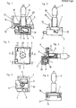
Die Figuren 1 bis 6 zeigen einen Glimmlampeneinsatz des ersten Ausführungsbeispiels, der im Boden des Schaltersockels befestigbar ist; die Figuren 7 bis 12 zeigen einen Glimmlampeneinsatz des zweiten Ausführungsbeispiels, der auf der Oberseite des Schaltersockels, seitlich vom Schalterbetätigungselement, befestigbar ist.Figures 1 to 6 show a glow lamp insert of the first embodiment, which can be fastened in the bottom of the switch base; Figures 7 to 12 show a glow lamp insert of the second embodiment, which can be attached to the top of the switch base, to the side of the switch actuating element.
Es zeigt:
- Fig. 1 eine Seitenschnittansicht des in einen Schaltersockel eingesetzten erfindungsgemäßen Glimmlampeneinsatzes gemäß der Schnittlinie I-I der Fig. 3,
- Fig. 2 eine Seitenansicht des Glimmlampeneinsatzes,
- Fig. 3 eine Aufsicht auf den Glimmlampeneinsatz von oben mit einer Darstellung der am Glimmlampeneinsatz ausgeführten Schnittlinien, wobei die römischen Ziffern auf die entsprechenden Figuren bezogen sind und die Pfeilrichtung die Blickrichtung angibt,
- Fig. 4 eine weitere Seitenschnittansicht des Glimmlampensockels gemäß der versetzten Schnittlinie IV-IV in Fig. 3,
- Fig. 5 eine Draufsicht auf den Oberteil des Glimmlampengehäuses von der dem Unterteil des Glimmlampengehäuses zugewandten Seite,
- Fig. 6 eine weitere Seitenschnittansicht des Glimmlampeneinsatzes gemäß der Schnittlinie VI-VI in Fig. 3,
- Fig. 7 eine Draufsicht auf die den Schalterkontaktteilen zugewandte Unterseite des Glimmlampeneinsatzes des zweiten Ausführungsbeispiels sowie eine Darstellung der Schnittlinien, bezogen auf die den römischen Ziffern entsprechenden Figuren,
- Fig. 8 eine Seitenschnittansicht des zweiten Ausführungsbeispieles gemäß der Schnittlinie VIII-VIII in Fig. 7,
- Fig. 9 eine weitere Seitenschnittansicht des zweiten Ausführungsbeispiels gemäß der versetzten Schnittlinie IX-IX in Fig. 7,
- Fig. 10 eine Seitenansicht des Glimmlampeneinsatzes des zweiten Ausführungsbeispiels,
- Fig. 11 eine weitere Seitenschnittansicht des Glimmlampeneinsatzes des zweiten Ausführungsbeispiels gemäß der Schnittlinie XI-XI in Fig. 7,
- Fig. 12 eine Aufsicht auf die den Schalterkontaktteilen abgewandte Seite des Glimmlampeneinsatzes des zweiten Ausführungsbeipiels.
- 1 is a side sectional view of the glow lamp insert according to the invention used in a switch base according to section line II of FIG. 3,
- 2 is a side view of the glow lamp insert,
- 3 shows a top view of the glow lamp insert from above with a representation of the cutting lines carried out on the glow lamp insert, the Roman numerals relating to the corresponding figures and the direction of the arrow indicating the direction of view,
- 4 shows a further side sectional view of the glow lamp base according to the offset section line IV-IV in FIG. 3,
- 5 is a plan view of the upper part of the glow lamp housing from the side facing the lower part of the glow lamp housing,
- 6 shows a further side sectional view of the glow lamp insert according to the section line VI-VI in FIG. 3,
- 7 is a plan view of the underside of the glow lamp insert of the second exemplary embodiment facing the switch contact parts and a representation of the cutting lines, based on the figures corresponding to the Roman numerals,
- 8 is a side sectional view of the second embodiment according to the section line VIII-VIII in Fig. 7,
- 9 shows a further side sectional view of the second exemplary embodiment according to the offset cutting line IX-IX in FIG. 7,
- 10 is a side view of the glow lamp insert of the second embodiment,
- 11 shows a further side sectional view of the glow lamp insert of the second exemplary embodiment according to the section line XI-XI in FIG. 7,
- Fig. 12 is a plan view of the side facing away from the switch contact parts of the glow lamp insert of the second exemplary embodiment.
Gemäß dem in den Figuren 1 bis 6 dargestellten ersten Ausführungsbeispiel besteht der Glimmlampeneinsatz im wesentlichen aus einem Oberteil 1 und einem Unterteil 2 eines Glimmlampengehäuses, welches durch erste und zweite eine Rastverbindung bildende Rastnasen 13, 14 zusammengehalten wird, einer Glimmlampe 3, einem der Strombe grenzung dienenden Vorwiderstand 4, einer in einem Fach des Oberteils 1 des Glimmlampengehäuses angeordneten Anschlußklemme 6, einer ersten Kontaktfeder 5 und einer zweiten Kontaktfeder 7, sowie einer ersten und einer zweiten Zuführungsleitung 8, 9. Erste Kontaktfeder 5, erste Zuführungsleitung 8, Vorwiderstand 4, Glimmlampe 3, zweite Zuführungsleitung 9 sowie zweite Kontaktfeder 7 sind in dieser Reihenfolge elektrisch in Reihe geschaltet.According to the first exemplary embodiment shown in FIGS. 1 to 6, the glow lamp insert essentially consists of an
Die als Federklemme ausgebildete Anschlußklemme 6 besteht aus einem Klemmstück 10 und einer Blattfeder 11. Das Klemmstück 10 besteht vorzugsweise aus einem U-förmigen Metallstück, an dessen einer Wandung eine V-förmige Rille 30 eingeformt ist. Diese Rille 30 dient der klemmfesten Aufnahme eines Leitungsdrahtes 21. Die Blattfeder 11 besteht aus einem im wesentlichen V-förmig gebogenen Stück Bandmetall. Aufgrund der an der gebogenen Blattfeder 11 auftretenden Druckspannung wird sowohl die zweite Zuführungsleitung 9 als auch die zweite Kontaktfeder 7 gegen eine Wandung des Klemmstückes 10 gepreßt und festgehalten. Weiter wird dadurch, daß der eine Klemmschenkel der Blattfeder 11 einen spitzen Winkel, vorzugsweise 45°, mit dem einen Ende der zweiten Kontaktfeder 7 bildet, sowie dadurch, daß der eine Schenkel scharfrandig in die zweite Kontaktfeder 7 eingreift, ein Herausrutschen der zweiten Kontaktfeder 7 weitgehend verhindert. Sofern man mit einem geeigneten Werkzeug (z.B. einem Schraubendreher) durch zwei sich überlappende, sowohl im Oberteil 1 als auch im Unterteil 2 des Glimmlampengehäuses angebrachte Durchbrüche 15 hindurchgreift und die Blattfeder 11 gegen die vorliegende Spannung zusammendrückt, läßt sich die zweite Kontaktfeder 7 herausschieben. Auf dem gleichen Weg läßt sich der Leitungsdraht 21 einschieben und festklemmen. Da die Anschlußklemme 6 als Federklemme ausgebildet ist, läßt sich in einfacher und zweckmäßiger Weise auch ein Ende der zweiten Zuführungsleitung 9 zwischen Klemmstück 10 und Blattfeder 11 der Anschlußklemme 6 einklemmen, wie insbesondere Figur 4 zeigt. Die zweite Kontaktfeder 7 ist im mittleren Bereich zum Zwecke des Aufbaues einer Federdruckkraft S-förmig gebogen und somit federnd elastisch ausgebildet. Die Kontaktfahne 12 der zweiten Kontaktfeder 7 wird durch das eine Ende der zweiten Kohtaktfeder 7 gebildet, welches aus dem Oberteil 1 des Glimmlampengehäuses herausragt.The
Wenn die am Oberteil 1 des Glimmlampengehäuses angeformte Hülse 19 zum Zwecke der zuverlässigen Halterung des Glimmlampeneinsatzes am Schaltersockel 17 in die entsprechende Sockelaufnahme 18 des Schaltersockels 17 eingeführt und mittels dritter Rastnasen 20 verrastend gehalten wird, drückt sich die entsprechend dimensionierte zweite Kontaktfeder 7 etwas zusammen, wodurch sie mit einem gewissen Kontaktdruck das Kontaktteil 16 des Schalters kontaktiert.If the
Die Figuren 7 bis 12 zeigen den Glimmlampeneinsatz des zweiten Ausführungsbeispiels. Der Glimmlampeneinsatz des zweiten Ausführungsbeispiels besteht im wesentlichen aus einem Glimmlampengehäuse 22, einer Glimmlampe 3, einem Vorwiderstand 4, einer ersten und zweiten Zuführungsleitung 8, 9, einer Anschlußklemme 26 sowie einer ersten und zweiten Kontaktfeder 25, 27. Was die Funktion der Einzelteile anlangt, gilt das zuvor beim ersten Ausführungsbeispiel Beschriebene.Figures 7 to 12 show the glow lamp insert of the second embodiment. The glow lamp insert of the second embodiment essentially consists of a
Über einen Teilbereich des Glimmlampengehäuses 22 wird ein hülsenartiges Gehäuseteil 23 geschoben und durch eine fünfte Rastnase 29 gehalten. Dies geschieht zum Zwecke der Halterung der Anschlußklemme 26, welche im übrigen gleich aufgebaut ist, wie die Anschlußklemme 6 des ersten Ausführungsbeispiels. Der Glimmlampeneinsatz des zweiten Ausführungsbeispiels wird mittels federnder Stege 24, an welchen vierte Rastnasen 28 angeformt sind, an der Sockelaufnahme 18 verrastend gehalten.A sleeve-
- 1 Oberteil des Glimmlampengehäuses1 upper part of the glow lamp housing
- 2 Unterteil des Glimmlampengehäuses2 lower part of the glow lamp housing
- 3 Glimmlampe3 glow lamp
- 4 Vorwiderstand4 series resistor
- 5 erste Kontaktfeder5 first contact spring
- 6 Anschlußklemme6 connecting terminal
- 7 zweite Kontaktfeder7 second contact spring
- 8 erste Zuführungsleitung8 first feed line
- 9 zweite Zuführungsleitung9 second feed line
- 10 Klemmstück der Anschlußklemme10 Clamp of the connection terminal
- 11 Blattfeder der "11 leaf spring of the "
- 12 Kontaktfahne der zweiten Kontaktfeder12 Contact tab of the second contact spring
- 13 erste Rastnasen13 first latches
- 14 zweite Rastnasen14 second latches
- 15 Durchbrüche am Glimmlampengehäuse15 openings on the glow lamp housing
- 16 Kontaktteil des Schalters16 contact part of the switch
- 17 Schaltersockel17 switch base
- 18 Sockelaufnahme18 base mounting
- 19 am Oberteil des Glimmlampengehäuses angeformte Hülse19 molded sleeve on the upper part of the glow lamp housing
- 20 dritte Rastnasen20 third latches
- 21 Leitungsdraht21 lead wire
- 22 Glimmlampengehäuse eines weiteren Ausführungsbeispiels22 Glow lamp housing of a further embodiment
- 23 hülsenartiges Gehäuseteil eines weiteren Ausführungsbsp.23 sleeve-like housing part of a further exemplary embodiment.
- 24 federnder Steg eines weiteren Ausführungsbeispiels24 resilient web of a further embodiment
- 25 erste Kontaktfeder eines weiteren Ausführungsbsp.25 first contact spring of a further exemplary embodiment.
- 26 Anschlußklemme " " "26 connecting terminal "" "
- 27 zweite Kontaktfeder" " "27 second contact spring "" "
- 28 vierte Rastnase " " "28 fourth latch "" "
- 29 fünfte Rastnase " "29 fifth latch ""
- 30 V-förmige Rille30 V-shaped groove
Claims (6)
Priority Applications (1)
| Application Number | Priority Date | Filing Date | Title |
|---|---|---|---|
| AT86113308T ATE68628T1 (en) | 1985-10-09 | 1986-09-26 | GLOW LAMP INSERT FOR ELECTRICAL INSTALLATION DEVICES. |
Applications Claiming Priority (2)
| Application Number | Priority Date | Filing Date | Title |
|---|---|---|---|
| DE19853536006 DE3536006A1 (en) | 1985-10-09 | 1985-10-09 | FLASH BULB INSERT FOR ELECTRICAL INSTALLATION DEVICES |
| DE3536006 | 1985-10-09 |
Publications (3)
| Publication Number | Publication Date |
|---|---|
| EP0222122A2 true EP0222122A2 (en) | 1987-05-20 |
| EP0222122A3 EP0222122A3 (en) | 1989-05-24 |
| EP0222122B1 EP0222122B1 (en) | 1991-10-16 |
Family
ID=6283149
Family Applications (1)
| Application Number | Title | Priority Date | Filing Date |
|---|---|---|---|
| EP86113308A Expired - Lifetime EP0222122B1 (en) | 1985-10-09 | 1986-09-26 | Discharge lamp fitting for electrical installation apparatuses |
Country Status (4)
| Country | Link |
|---|---|
| EP (1) | EP0222122B1 (en) |
| AT (1) | ATE68628T1 (en) |
| DE (2) | DE3536006A1 (en) |
| FI (1) | FI864032A (en) |
Cited By (2)
| Publication number | Priority date | Publication date | Assignee | Title |
|---|---|---|---|---|
| DE4405760A1 (en) * | 1994-02-23 | 1995-08-24 | Marquardt Gmbh | Lighting device and illuminated electric switch |
| EP0833547A1 (en) * | 1996-09-28 | 1998-04-01 | GIRA GIERSIEPEN GmbH. & CO. KG | Light signalling device |
Families Citing this family (5)
| Publication number | Priority date | Publication date | Assignee | Title |
|---|---|---|---|---|
| DE4317491A1 (en) * | 1993-05-26 | 1994-12-01 | Abb Patent Gmbh | Glow lamp to plug in |
| DE4409932C2 (en) * | 1994-03-12 | 2001-07-19 | Abb Patent Gmbh | Lighting insert |
| DE4408369C2 (en) * | 1994-03-12 | 2002-09-26 | Abb Patent Gmbh | Holder for a lamp |
| DE102005008755B3 (en) * | 2005-02-25 | 2006-05-24 | Siemens Ag | Modular electrical installation switch with replaceable illumination unit has base module with recess on switch rocker side for accommodation of illumination unit as insert into recess |
| DE102010014474B4 (en) * | 2010-04-09 | 2013-01-10 | Bjb Gmbh & Co. Kg | version |
Citations (3)
| Publication number | Priority date | Publication date | Assignee | Title |
|---|---|---|---|---|
| US3328551A (en) * | 1966-04-05 | 1967-06-27 | Square D Co | Detachable lamp assembly for electrical switch |
| DE1440766B1 (en) * | 1962-04-05 | 1970-10-15 | Berker Geb | Exchangeable lamp housing with built-in glow or glow lamp for use in electrical installation switches |
| DE1690400A1 (en) * | 1967-04-26 | 1971-05-27 | Vedder Gmbh Fabrik Elektrotech | Installation apparatus with screwless conductor connection terminals |
-
1985
- 1985-10-09 DE DE19853536006 patent/DE3536006A1/en not_active Withdrawn
-
1986
- 1986-09-26 EP EP86113308A patent/EP0222122B1/en not_active Expired - Lifetime
- 1986-09-26 DE DE8686113308T patent/DE3682020D1/en not_active Expired - Fee Related
- 1986-09-26 AT AT86113308T patent/ATE68628T1/en not_active IP Right Cessation
- 1986-10-06 FI FI864032A patent/FI864032A/en not_active Application Discontinuation
Patent Citations (3)
| Publication number | Priority date | Publication date | Assignee | Title |
|---|---|---|---|---|
| DE1440766B1 (en) * | 1962-04-05 | 1970-10-15 | Berker Geb | Exchangeable lamp housing with built-in glow or glow lamp for use in electrical installation switches |
| US3328551A (en) * | 1966-04-05 | 1967-06-27 | Square D Co | Detachable lamp assembly for electrical switch |
| DE1690400A1 (en) * | 1967-04-26 | 1971-05-27 | Vedder Gmbh Fabrik Elektrotech | Installation apparatus with screwless conductor connection terminals |
Cited By (2)
| Publication number | Priority date | Publication date | Assignee | Title |
|---|---|---|---|---|
| DE4405760A1 (en) * | 1994-02-23 | 1995-08-24 | Marquardt Gmbh | Lighting device and illuminated electric switch |
| EP0833547A1 (en) * | 1996-09-28 | 1998-04-01 | GIRA GIERSIEPEN GmbH. & CO. KG | Light signalling device |
Also Published As
| Publication number | Publication date |
|---|---|
| FI864032A (en) | 1987-04-10 |
| EP0222122A3 (en) | 1989-05-24 |
| ATE68628T1 (en) | 1991-11-15 |
| EP0222122B1 (en) | 1991-10-16 |
| FI864032A0 (en) | 1986-10-06 |
| DE3682020D1 (en) | 1991-11-21 |
| DE3536006A1 (en) | 1987-04-09 |
Similar Documents
| Publication | Publication Date | Title |
|---|---|---|
| EP1614200A1 (en) | Overvoltage protection magazine for a device of telecommunications technology | |
| DE2825201C2 (en) | Contact device | |
| EP0222122A2 (en) | Discharge lamp fitting for electrical installation apparatuses | |
| DE3447135A1 (en) | Screwless connecting and joining terminal for electrical leads | |
| EP0108235B1 (en) | Device for the screwless connection of two parts | |
| DE3004211A1 (en) | Terminal cover for e.g. circuit interrupter - has fixing for engaging switch casing and holding cover in place | |
| DE2914507C2 (en) | ||
| DE102009008934A1 (en) | Electrical connecting terminal i.e. series terminal, for use as frontal terminal, has spring force element including opening via which current bar directly contacts conductor, where bar is arranged on spring force element | |
| DE1230880B (en) | Electric switch with sliding actuator | |
| DE2634697C3 (en) | Direction indicator and hazard warning switches in motor vehicles | |
| DE3422768A1 (en) | Electrical apparatus | |
| DE2339504C2 (en) | Clamping device for insulated electrical conductors | |
| DE8502551U1 (en) | CONTACT PLIERS, ESPECIALLY FOR THE ELECTROPHORETIC PAINTING OF METAL PARTS | |
| DE2836974C2 (en) | Interior light | |
| EP0156291A2 (en) | Compact fluorescent lamp | |
| DE2646611C2 (en) | Fuse terminal with exchangeable glow lamp | |
| DE2353416A1 (en) | ELECTRIC SWITCH | |
| DE2460856C2 (en) | Device for electrical connection | |
| DE3243290C2 (en) | Fastening device for a leaf spring contact switch | |
| EP0336251A2 (en) | Clamping screw | |
| DE19727927A1 (en) | Connection device for insulated electrical conductors without stripping | |
| DE3304121C2 (en) | Bimetal switch | |
| DE3019106C2 (en) | Electrical connector | |
| DE7318348U (en) | DEVICE FOR ATTACHING A LIGHTING BODY TO A CEILING AND CONNECTING TO AN ELECTRICAL MAINS | |
| DE3222597A1 (en) | Electrical plug device, such as a plug or coupling socket |
Legal Events
| Date | Code | Title | Description |
|---|---|---|---|
| PUAI | Public reference made under article 153(3) epc to a published international application that has entered the european phase |
Free format text: ORIGINAL CODE: 0009012 |
|
| AK | Designated contracting states |
Kind code of ref document: A2 Designated state(s): AT BE DE FR SE |
|
| RAP1 | Party data changed (applicant data changed or rights of an application transferred) |
Owner name: ASEA BROWN BOVERI AKTIENGESELLSCHAFT |
|
| PUAL | Search report despatched |
Free format text: ORIGINAL CODE: 0009013 |
|
| AK | Designated contracting states |
Kind code of ref document: A3 Designated state(s): AT BE DE FR SE |
|
| 17P | Request for examination filed |
Effective date: 19890705 |
|
| 17Q | First examination report despatched |
Effective date: 19900816 |
|
| GRAA | (expected) grant |
Free format text: ORIGINAL CODE: 0009210 |
|
| AK | Designated contracting states |
Kind code of ref document: B1 Designated state(s): AT BE DE FR SE |
|
| REF | Corresponds to: |
Ref document number: 68628 Country of ref document: AT Date of ref document: 19911115 Kind code of ref document: T |
|
| REF | Corresponds to: |
Ref document number: 3682020 Country of ref document: DE Date of ref document: 19911121 |
|
| ET | Fr: translation filed | ||
| PLBE | No opposition filed within time limit |
Free format text: ORIGINAL CODE: 0009261 |
|
| STAA | Information on the status of an ep patent application or granted ep patent |
Free format text: STATUS: NO OPPOSITION FILED WITHIN TIME LIMIT |
|
| 26N | No opposition filed | ||
| PGFP | Annual fee paid to national office [announced via postgrant information from national office to epo] |
Ref country code: AT Payment date: 19930805 Year of fee payment: 8 |
|
| PGFP | Annual fee paid to national office [announced via postgrant information from national office to epo] |
Ref country code: SE Payment date: 19930830 Year of fee payment: 8 Ref country code: FR Payment date: 19930830 Year of fee payment: 8 |
|
| PGFP | Annual fee paid to national office [announced via postgrant information from national office to epo] |
Ref country code: DE Payment date: 19930902 Year of fee payment: 8 |
|
| PGFP | Annual fee paid to national office [announced via postgrant information from national office to epo] |
Ref country code: BE Payment date: 19930906 Year of fee payment: 8 |
|
| PG25 | Lapsed in a contracting state [announced via postgrant information from national office to epo] |
Ref country code: AT Effective date: 19940926 |
|
| PG25 | Lapsed in a contracting state [announced via postgrant information from national office to epo] |
Ref country code: SE Effective date: 19940927 |
|
| PG25 | Lapsed in a contracting state [announced via postgrant information from national office to epo] |
Ref country code: BE Effective date: 19940930 |
|
| EAL | Se: european patent in force in sweden |
Ref document number: 86113308.0 |
|
| BERE | Be: lapsed |
Owner name: ASEA BROWN BOVERI A.G. Effective date: 19940930 |
|
| PG25 | Lapsed in a contracting state [announced via postgrant information from national office to epo] |
Ref country code: FR Effective date: 19950531 |
|
| PG25 | Lapsed in a contracting state [announced via postgrant information from national office to epo] |
Ref country code: DE Effective date: 19950601 |
|
| EUG | Se: european patent has lapsed |
Ref document number: 86113308.0 |
|
| REG | Reference to a national code |
Ref country code: FR Ref legal event code: ST |