EP0222074B1 - Arbitrierungsvorrichtung zur Bestimmung der Zugriffspriorität auf einen gemeinsamen Bus - Google Patents
Arbitrierungsvorrichtung zur Bestimmung der Zugriffspriorität auf einen gemeinsamen Bus Download PDFInfo
- Publication number
- EP0222074B1 EP0222074B1 EP86111148A EP86111148A EP0222074B1 EP 0222074 B1 EP0222074 B1 EP 0222074B1 EP 86111148 A EP86111148 A EP 86111148A EP 86111148 A EP86111148 A EP 86111148A EP 0222074 B1 EP0222074 B1 EP 0222074B1
- Authority
- EP
- European Patent Office
- Prior art keywords
- signal
- arbiter
- request
- access
- gate
- Prior art date
- Legal status (The legal status is an assumption and is not a legal conclusion. Google has not performed a legal analysis and makes no representation as to the accuracy of the status listed.)
- Expired
Links
Images


Classifications
-
- G—PHYSICS
- G06—COMPUTING OR CALCULATING; COUNTING
- G06F—ELECTRIC DIGITAL DATA PROCESSING
- G06F13/00—Interconnection of, or transfer of information or other signals between, memories, input/output devices or central processing units
- G06F13/14—Handling requests for interconnection or transfer
- G06F13/20—Handling requests for interconnection or transfer for access to input/output bus
- G06F13/28—Handling requests for interconnection or transfer for access to input/output bus using burst mode transfer, e.g. direct memory access DMA, cycle steal
- G06F13/30—Handling requests for interconnection or transfer for access to input/output bus using burst mode transfer, e.g. direct memory access DMA, cycle steal with priority control
-
- G—PHYSICS
- G06—COMPUTING OR CALCULATING; COUNTING
- G06F—ELECTRIC DIGITAL DATA PROCESSING
- G06F13/00—Interconnection of, or transfer of information or other signals between, memories, input/output devices or central processing units
- G06F13/14—Handling requests for interconnection or transfer
-
- G—PHYSICS
- G06—COMPUTING OR CALCULATING; COUNTING
- G06F—ELECTRIC DIGITAL DATA PROCESSING
- G06F13/00—Interconnection of, or transfer of information or other signals between, memories, input/output devices or central processing units
- G06F13/14—Handling requests for interconnection or transfer
- G06F13/36—Handling requests for interconnection or transfer for access to common bus or bus system
- G06F13/362—Handling requests for interconnection or transfer for access to common bus or bus system with centralised access control
- G06F13/364—Handling requests for interconnection or transfer for access to common bus or bus system with centralised access control using independent requests or grants, e.g. using separated request and grant lines
Definitions
- the present invention pertains to an arbitration apparatus which resolves priority of access to a shared bus based on a rotating priority scheme, the scheme being selectively changeable by the user.
- various processors and input/output units disposed within the computer system may require access to a common shared data bus at approximately the same time.
- the data bus can handle only one access at a time. Therefore, some mechanism must be utilized to determine which unit and which processor may be granted access to the bus.
- an instruction processor unit 10a is connected to an instruction cache (I-cache) 10b and a data cache (D-cache) 10c.
- the instruction cache 10b and the data cache 10c are further connected to a common storage facility 10d and to an input/output interface unit logic circuit (IOIU logic) 10e via a storage bus 10f.
- a storage control logic circuit 10g is connected to the common storage facility 10d via a control bus 10h and interfaces with the IOIU logic circuit 10e.
- the IOIU logic circuit 10e further interfaces with an arbiter logic circuit 10i according to the present invention.
- Refresh logic 10x is disposed within said arbiter logic circuit 10i.
- the IOICs 10j, 10k, 10L, and 10m are connected to various I/O subunits 10p, 10q, 10r, and 10s via I/O buses 10t, 10u, 10v, and 10w, respectively.
- the arbiter logic circuit 10i receives bus adaptor access requests from the storage control logic 10g via line 7, an access request from the refresh logic 10x via line 8, and a PBO CS request from the storage control logic 10g via line 9.
- the instruction processor unit (IPU) 10a executes instructions stored in the instruction cache 10b utilizing data stored in the data cache 10c.
- the results of the execution of the instructions are stored in the common storage facility 10d. If it is necessary to transfer the results to various ones of the I/O subunits 10p, 10q, 10r, and 10s, the results are retrieved from the common storage facility 10d by the storage control logic 10g and are transferred to the adapter bus 10n via the IOIU logic 10e and to the I/O subunits 10p through 10s via the IOICs 10j through 10m.
- the instruction cache 10b, the data cache 10c, and/or one or more of the IOICs 10j through 10m may require access to the shared buses (storage bus 10f, and the adapter bus 10n) simultaneously. Since the shared buses can handle only one access at a time, some arbitration mechanism must be utilized to determine which unit will access the shared bus at a particular point in time. In order to make this determination, a plurality of units needing access, comprising the data cache 10c, the instruction cache 10b, the IOIC 1 10j, the IOIC 2 10k, the IOIC 3 10L, the IOIC 4 10m, the storage control logic 10g and the refresh logic 10x, each generate an access request signal which is directed to the arbiter logic 10i via lines 1 through 9.
- a third individual arbiter 10i3, third in order of priority relative to other individual arbiters, represents the IOIC normal request rotator arbiter used for data transfers. This second IOIC level of arbitration prevents the normal data transfers from interfering with the command transfers which could cause device overruns.
- the third arbiter receives normal requests from the IOIC subunits 10j through 10m.
- a fourth individual arbiter 10i4, fourth in order of priority relative to other individual arbiters represents an I-cache request fixed priority arbiter.
- the fourth arbiter receives access requests from the instruction cache 10b.
- a fifth individual arbiter 10i5, fifth in order of priority relative to other individual arbiters, represents a D-cache request fixed priority arbiter.
- the fifth arbiter receives access requests from the data cache 10c.
- a sixth individual arbiter 10i6, sixth in order of priority relative to other individual arbiters, represents a bus adapter, fixed priority, arbiter.
- the sixth arbiter receives access requests from the storage control logic 10g.
- the first individual arbiter 10i1 has a request input terminal and an enable input terminal.
- the request input terminal is connected, in parallel, to each of IOIC's 1 through 4 representing I/O subunits 10p, 10q, 10r, and 10s, respectively, of Figure 1.
- the enable input terminal of the first individual arbiter 10i1 is connected to an output terminal of a AND gate 10i1a.
- the input terminals of the AND gate 10i1a receive the "no refresh pending" input signal and the "allow arbitration" input signal.
- the AND gate 10i1a has the following truth table: all inputs must be positive for the output to be positive; any inputs which are negative will cause the output to be negative.
- the first individual arbiter 10i1 is connected to a first command rotor 10i1b.
- the command rotor 10i1b stores numbers 1 through 4 corresponding to subunits 1 through 4, respectively, the command requests of which are being input to the request input terminal of the first individual arbiter 10i1.
- the command rotor 10i1b stores, in Figure 2a, numbers 4, 1, 2, and 3, in sequence, any sequence of numbers may be stored in the command rotor.
- command rotor 10i1b could easily store numbers 1, 1, 2, 3, or numbers 1, 2, 3, 3, etc.
- the command rotor 10i1b may be depicted as "rotating". That is, as the command rotor "rotates", numbers 4, 1, 2, 3 will be input to the first individual arbiter 10i1 representing IOIC's 4, 1, 2, and 3, in sequence.
- the rotors are not limited to four entries, they may contain any number of entries. The number of entries or slots available will determine the granularity of the percent priority each entry possesses.
- arbiter 10i1 Assume that IOIC's command requests are being input to arbiter 10i1 by all four IOIC's 1-4. Therefore, the request input terminal of arbiter 10i1 is receiving four command request signals from IOIC's 1 through 4, respectively. Further, assume that the command rotor 10i1b is positioned as shown in Figure 2a, that is, the number 4 is being input to arbiter 10i1. This first arbiter 10i1 can be thought of as an arbiter having 4 input request lines but containing 5 levels of fixed descending priority arbitration. The top priority level is determined by the value contained in the rotor 10i1b.
- a positive signal energizes the enable terminal of arbiter 10i1.
- IOIC's 4, 1, 2, and 3 are sequentially granted access to the shared bus. Therefore, command request signals corresponding to IOIC's 4, 1, 2, and 3 sequentially energize the shared bus. If either or both of the "no refresh pending" or “allow arbitration” signals are not positive, a negative signal energizes the enable terminal of arbiter 10i1. If a negative signal energizes the enable terminal, IOIC's 1-4 are all denied access to the shared bus.
- Access to the shared bus by IOIC's 1-4 via arbiter 10i1 is higher in priority than a PBO cycle steal access request to the shared bus via arbiter 10i2. If IOIC's 1-4 are not requesting access to the shared bus via arbiter 10i1, the PBO cycle steal request via arbiter 10i2 may be granted.
- the IOIC command requests via arbiter 10i1 have highest priority, among the arbiters of Figures 2a - 2c, and the PBO cycle steal request via arbiter 10i2 has secondary priority.
- the enable terminal of arbiter 10i2 is connected to the output terminal of another AND gate 10i2b having a truth table which is the same as the truth table for AND gate 10i1a.
- the input terminals of AND gate 10i2b receive the "allow arbitration” signal and the "no IOIC command requests” signal.
- the "no IOIC command requests” signal represents an output signal from a negative AND gate 10i2a.
- IOIC command access requests (IOIC 1 command req, IOIC 2 command req, etc), which energize the request terminal of arbiter 10i1, also energize the input terminals of the negative AND gate 10i2a. Therefore, if any IOIC command request is high, the output of negative AND gate 10i2a is low, whereas, if all IOIC command requests are low, the output of negative AND gate 10i2a is high.
- the output of AND gate 10i2a is appropriately labelled "+no IOIC command req's". This labelling convention indicates that, if there are no high (active) IOIC command requests energizing the request terminal of arbiter 10i1, the first input terminal of AND gate 10i2b is high.
- AND gate 10i3a receives the following input signals: "no refresh pending", “no IOIC command request”, “no PBO CS request”, and "allow arbitration".
- AND gate 10i3a has a truth table which is the same as that of AND gate 10i1a, that is, all positive inputs yield a positive output; any other combination yields a negative output.
- a negative signal, energizing the enable terminal of arbiter 10i3, will block all IOIC normal requests from gaining access to the shared bus via the request terminal of arbiter 10i3.
- a command rotor 10i3b is connected to the arbiter 10i3 and functions in the same manner as that of rotor 10i1b.
- IOIC's 1-4 will be granted access to the bus via arbiter 10i3 in an order defined by the "rotation" of command rotor 10i3b.
- IOIC's 1-4 in response to a counterclockwise rotation of rotor 10i3b, IOIC's 1-4 will be given highest priority to the bus in the following order: subunits 3, 4, 1, and 2. If the selection for highest priority is not matched with its respective request, the remaining requests are handled in a fixed descending priority order.
- arbiter 10i4 receives an I-cache request at its request terminal. If access requests are not being received by arbiters 10i1, 10i2, or 10i3 of Figure 2a, the I-cache request received by arbiter 10i4 may be granted access to the shared bus, provided the signal being received at the enable terminal of arbiter 10i4 is positive.
- Arbiter 10i4 ranks fourth in priority relative to arbiters 10i1, 10i2, and 10i3.
- the enable terminal of arbiter 10i4 is connected to the output of a AND gate 10i4a.
- the AND gate 10i4a possesses the same truth table as that of AND gate 10i3a.
- the enable terminal of arbiter 10i5 is connected to the output terminal of AND gate 10i5a.
- the AND gate 10i5a possesses a truth table which is the same as that of AND gates 10i4a and 10i3a.
- the input terminals of AND gate 10i5a receive the following input signals: "no refresh pending", a positive signal indicating that no refresh is pending; "no IOIC command requests” (see AND gate 10i2b description); “no PBO CS REQ” (see AND gate 10i3a description); “no IOIC normal requests” (see AND gate 10i4a description); "no I-cache request", a positive signal meaning that there is no I-cache request being received by arbiter 10i4; and "allow arbitration", a positive signal indicating nothing is prohibiting arbitration. If all of these signals are positive, a positive signal is received at the enable terminal of arbiter 10i5, and, as a result, the D-cache request, received at the request terminal of arbiter 10
- refresh logic 10x including arbiters 10i7 and 10i8, is illustrated.
- arbiter 10i7 receives a refresh request signal at its request terminal. If arbiters 10i1, 10i2, 10i3, 10i4, 10i5, and 10i6 do not receive access requests, arbiter 10i7 may grant the refresh access request if the signal at its enable terminal is positive.
- Arbiter 10i7 ranks seventh in order of priority relative to arbiters 10i1 through 10i6.
- the enable terminal of arbiter 10i7 is connected to an output terminal of AND gate 10i7a.
- AND gate 10i7a possesses the same truth table as that of AND gate 10i6a and the other AND gates.
- AND gate 10i7a receives the following input signals: "no IOIC command requests”, a positive signal indicating that IOIC's command requests are not received by arbiter 10i1; “no IOIC normal requests”, a positive signal indicating that the subunit normal requests are not received by arbiter 10i3; “no I-cache request”, a positive signal indicating that an I-cache request is not received by arbiter 10i4; "no D-cache request”, a positive signal indicating that a D-cache request is not received by arbiter 10i5; and "allow arbitration", a positive signal indicating that no signal exists which would prevent arbitration from continuing.
- the enable terminal of arbiter 10i7 is also connected to an AND gate 10i7b via an inverter 10i7c.
- the other input terminal of the AND gate 10i7b is connected to the refresh request signal which is energizing the request terminal of the arbiter 10i7.
- the output of the AND gate 10i7b is connected to the set terminal of a set/reset latch circuit 10i7d.
- the Q output of the latch circuit 10i7d is connected to the request terminal of a further arbiter 10i8.
- the output terminal of the further arbiter 10i8 is connected to one input terminal of an OR gate 10i9.
- the other input terminal of the OR gate 10i9 is connected to the output terminal of the arbiter 10i7.
- the output terminal of the OR gate 10i9 labelled "refresh grant”, is connected to the reset terminal of the latch circuit 10i7d.
- the Q output of the latch circuit 10i7d is labelled “+refresh pending” and the Q bar output of the latch circuit 10i7d is labelled “no refresh pending”. This is the signal connected to the enable AND gates of arbiters 10i1, 10i3, 10i4, 10i5, 10i6.
- the functional operation of the refresh logic 10x will be described in the following paragraph with reference to Figure 2c.
- a positive Q output signal (the +REFRESH PENDING signal) from the latch circuit 10i7d represents a refresh pending condition (which means that some higher request was active at the same time the refresh request was active and the refresh operation will be delayed until the other operation has completed).
- the "allow arbitration" signal goes active which allows the output of arbiter 10i8 to become active.
- This output signal is fed to the input of OR gate 10i9 which now causes the refresh grant signal to be generated. Since the "refresh request" signal is only active for one cycle, the latch 10i7d will be set during the time some other storage operation is in progress.
- the Q-output signal of the latch circuit 10i7d which generates the +REFRESH PENDING signal, signifies that a refresh operation is pending and will be taken as soon as the "allow arbitration" signal becomes active.
- the command rotors represent, as in Figure 3a, a simple memory with a pointer addressing the memory. As the pointer addresses the memory, the subunit numbers stored therein are read out in sequence. However, in Figure 3b, a different set of subunit numbers are stored in the memory. In fact, any set of subunit numbers may be stored in the memory. Therefore, the set of subunit numbers to be stored in the memory is selectively changeable by the user. In the Figure 3b embodiment, subunit numbers 1, 2, 2, 3, 3, and 4 are read out in sequence.
- subunit 3 must be granted access to the shared bus more frequently than subunit 1, or subunit 4, the subunit number 3 should be stored a multiple number of times in the memory.
- the percentage of top priority grants is established by the number of times a subunits address appears in the memory array.
- the granularity of the percentage of highest priority is inversely proportional to the number of slots used. In other words, if only four memory slots were used, each subunit would be guaranteed highest priority 25% of the time. If eight slots were used, the percentage would be 12.5 thus giving 37.5% to a subunit having 3 entries.
- the inputs 1DCD, 2DCD,..., and 4DCD, represent the individual outputs from decoder b4(1).
- a number is stored in each of the registers b2a, b2b, b2c,...,b2n, each of the numbers representing a particular subunit command request, energizing the request terminal of arbiter 10i1, or representing a particular subunit normal request, energizing the request terminal of arbiter 10i3.
- the numbers, stored in these respective registers are binary numbers "10, 11, 10,..., and 01".
- the numbers are selected from each of the registers b2a, b2b, b2c,..., and b2n, in sequence, starting with the binary number 10, by the gate means b3.
- Latch circuit b3a generates an output signal energizing gate b3 thereby selecting the output from register b2a, latch circuit b3b generating an output signal energizing gate b3 thereby selecting the output from register b2b, etc.
- multiplexer b1 generates output signals representing the numbers stored in registers b2a, b2b, b2c, ..., and b2n, respectively.
- the decoder b4(1) receives the output signals from the multiplexer b1 and develops corresponding output signals, in sequence, labeled 1DCD, 2DCD,..., 4DCD, starting with the "1DCD" output signal.
- These corresponding output signals developed from the decoder b4(1) sequentially energize a plurality of gates b4a, b4b,..., b4n. Each of these gates b4a,...,b4n also simultaneously receive request signals labeled "+ request 1, + request 2, ...., + request 4". These request signals represent the IOIC command request signals energizing the arbiter 10i1 and the IOIC normal request signals energizing the arbiter 10i3.
- the gates b4a, b4b, ..., b4n generate an output signal representing the fact that the selected highest priority, determined by the priority register selected by the gate means b3, matched its associated request signal and will therefore be granted access to the shared bus on the next cycle.
- IOIC subunits 4, 1, 2, and 3 will be granted access to the shared bus provided the "no refresh pending" signal is positive, indicating that there is no refresh pending, the "no IOIC command request” signal is positive, indicating there are no IOIC command requests energizing the request terminal of arbiter 10i1, the "no PBO CS request” signal is positive indicating there is no PBO cycle steal request energizing the request terminal of arbiter 10i2, and the "allow arbitration” is also positive, indicating there is no operation in progress which would prevent arbitration from continuing.
- I-Cache preemptive grant There is a second method of generating an I-Cache grant called the I-Cache preemptive grant. It is generated from the 10i4c AND gate if the "no higher requests" signal is positive, indicating arbiters 10i1, 10i2, and 10i3 do not have their respective request terminals active, the "no lower grants” signal is positive, indicating no grants were given to the D-Cache, the Bus Adapter, or refresh, and the "allow arbitration” as well as the "no refresh cycle” signals are positive, indicating that no data transfer operation or refresh operation is in progress.
- bus adapter request If the "bus adapter request" signal is energizing the request terminal of arbiter 10i6, it will be granted access to the shared bus, and the "bus adapter grant” signal will be developed from arbiter 10i6 provided that all higher requests are not energizing the request terminals of arbiters 10i1 through 10i5, and provided that the "no refresh pending" and the “allow arbitration” signals, energizing gate 10i6a, are positive. Each of the signals energizing gate 10i6a must be positive in order to allow the "bus adapter request" signal access to the shared bus.
- An output from AND gate 10i7b sets latch 10i7d.
- an output from the Q output terminal energizes the request terminal of arbiter 10i8.
- An output signal is generated from arbiter 10i8 when the allow arbitration signal goes active at the end of the operation currently in progress. This signal energizes OR gate 10i9 which causes a "refresh grant signal to be generated. The refresh operation will commence immediately following the termination of the previous operation (the previous operation is causing one of the signals energizing gate 10i7a to be negative). This grant signal from OR gate 10i9 will also force the refresh pending latch 10i7d to be reset.
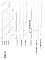
- FIGS 5 through 7 a set of timing diagrams 1 through 3 illustrate a typical timing sequence of the arbitration process.
- timing diagram 1 depicts the timing sequence for either an I/O request or a D-Cache request.
- the "NO HIGHER REQUEST” signal is positive, meaning no higher request than the current level of request is active, and "ALLOW ARBITRATION” signal is positive, meaning it is safe to arbitrate at the next T0.
- the GRANT is given out at T1 to the unit whose request was active at T0.
- the I-Cache grant signal is taken away since some other grant was activated during this cycle.
- the "allow arbitration” signal is deactivated to prevent further arbitration while the current operation is in progress.
- the requesting unit will continue to sample its grant signal at T3 until it finds the signal active, and will then place its command and address on the shared bus on the following cycle, in this case, cycle 3.
- timing diagram 3 depicts the normal I-Cache grant sequence when the shared facility is busy.
- the I-Cache request signal is activated, however, I-Cache grant is not active since the "ALLOW ARBITRATION” signal is inactive at T0.
- Arbitration takes place in cycle 2 since the "ALLOW ARBITRATION” signal is positive at T0.
- the arbiter activates the "I-CACHE GRANT” signal which is detected by the I-Cache at T3.
- the I-Cache then activates the command and address on the shared bus during cycle 3. This sequence is known as a normal I-Cache grant.
Landscapes
- Engineering & Computer Science (AREA)
- Theoretical Computer Science (AREA)
- Physics & Mathematics (AREA)
- General Engineering & Computer Science (AREA)
- General Physics & Mathematics (AREA)
- Bus Control (AREA)
- Multi Processors (AREA)
Claims (6)
- Entscheidungseinrichtung in einem Rechnersystem mit einer Mehrzahl von Untereinheiten (10b, 10c, 10g, 10x, 10j-10m), die einen Zugriff auf ein gemeinsames Busbetriebsmittel (10f) anfordern, wobei die Entscheidungseinrichtung folgendes aufweist:
eine Mehrzahl einzelner Entscheidungsmittel (10i1-10i7), die in einer Prioritätsfolge angeordnet sind, wobei jedes der Entscheidungsmittel folgendes aufweist: einen Anforderungsanschluß (REQ), um ein Signal für eine Zugriffsanforderung aus zumindest einer der Untereinheiten zu empfangen, die einen Zugriff auf den gemeinsamen Bus suchen, und einen Aktivierungsanschluß (+ENABLE), um ein Aktivierungssignal zu empfangen, wobei das Aktivierungssignal aktiv ist, wenn keine Zugriffsanforderung an einen Entscheider gestellt wurde, der in der Prioritätsfolge höher steht, wodurch ein Entscheidungsmittel ein Gewährungssignal für einen Zugriff auf den gemeinsamen Bus bildet, wenn sowohl sein Anforderungsanschluß als auch sein Aktivierungsanschluß angeregt sind,
wobei die Entscheidungseinrichtung dadurch gekennzeichnet ist, daß
zumindest eines der Entscheidungsmittel (10i1 oder 10i3) eine Mehrzahl von Signalen für eine Zugriffsanforderung empfängt und eine Mehrzahl von Gewährungssignalen für einen Buszugriff erzeugt, die einem Untersatz (10j-10m) der Mehrzahl von Untereinheiten entsprechen und zumindest eines der Entscheidungsmittel folgendes aufweist:
Steuerungsspeichermittel (b2a-b2n), um eine Mehrzahl von Identifizierungssymbolen in denselben zu speichern, welche die Untereinheiten in dem Untersatz identifizieren, wobei die Steuerungsspeichermittel eine Wiederholungsfolge von Ausgangssignalen ('1'DCD,...,'n'DCD) erzeugen, die jeweils der Mehrzahl von Identifizierungssymbolen entsprechen und identifizieren, welche Untereinheiten in dem Untersatz höchste Priorität zu irgendeinem gegebenen Augenblick in der Wiederholungsfolge aufweist,
Erfassungsmittel (b4a-b4n) für eine Koinzidenz, wodurch ein Koinzidenzsignal erzeugt wird, wenn während der Wiederholungsfolge eines der Ausgangssignale eine Untereinheit identifiziert, die zu derselben Zeit ein Signal für eine Zugriffsanforderung erzeugt,
eine Anforderungsschaltung (b5) mit einer Mehrzahl von Latch-Mitteln (b5g-b5j), wobei jedes Latch-Mittel einer Untereinheit des Untersatzes entspricht und ein Signal für eine Zugriffsanforderung entsprechend einer festen Prioritätsreihenfolge hält, wenn das Koinzidenzsignal nicht aktiv ist,
wodurch das zumindest eine der Entscheidungsmittel, falls dieses aktiviert ist, einen Zugriff auf den gemeinsamen Bus folgenden gewährt:
entweder der Untereinheit des Untersatzes, die es bewirkt hat, daß das Koinzidenzsignal aktiv wurde,
oder der Untereinheit des Untersatzes mit der höchsten Priorität in der festen Prioritätsreihenfolge, wenn das Koinzidenzsignal nicht aktiv ist. - Entscheidungseinrichtung nach Anspruch 1,
bei welcher die Mehrzahl von Identifizierungssymbolen selektiv geändert werden kann, um einen neuen Satz von Identifizierungssymbolen zu bilden, welche die Elemente eines neuen Untersatzes der Mehrzahl von Untereinheiten identifizieren,
die Zeit, zu der einer speziellen Untereinheit ein Zugriff auf den gemeinsamen Bus gewährt ist, von der Anzahl abhängig ist, wie oft ihr entsprechendes Identifizierungssymbol in den Steuerungsspeichermitteln gespeichert ist. - Entscheidungseinrichtung nach Anspruch 1 oder 2, die ferner folgendes aufweist:
ein erstes Tormittel (10i4b), das als Eingaben das Gewährungssignal aus einem der Entscheidungsmittel (10i4) und das Ausgangssignal des zweiten Tormittels (10i4c) empfängt, wobei das Ausgangssignal anzeigt, daß kein Signal für eine Zugriffsanforderung ein Entscheidungsmittel anregt, das höher in der Prioritätsfolge steht und daß kein Gewährungssignal aus einem Entscheidungsmittel gebildet wird, das niedriger in der Folge steht,
wobei das Ausgangssignal des zweiten Tormittels ein wahlweise vergebbares Gewährungssignal ist, der Ausgang des ersten Tormittels angeregt ist, wenn irgendeiner seiner Eingänge aktiv ist,
und wodurch das eine der Entscheidungsmittel einen Zugriff auf den gemeinsamen Bus als nächstes gewährt, ein nachfolgender Maschinenzyklus dem Eintreffen seiner entsprechenden Zugriffsanforderung folgt, falls das wahlweise vergebbare Gewährungssignal beim Eintreffen der Zugriffsanforderung aktiv war, wodurch ein Entscheidungsmaschinenzyklus gesichert wird. - Entscheidungseinrichtung nach Anspruch 3,
bei welcher das Signal für eine Zugriffsanforderung ein Anforderungssignal für einen Befehls-Cache-Speicher ist, das von einer Untereinheit (10b) eines Befehls-Cache-Speicher gebildet wird, die innerhalb des Rechnersystems eingerichtet ist. - Entscheidungseinrichtung nach irgendeinem der Ansprüche 1 bis 4, die ferner folgendes aufweist:
dritte Tormittel (10i7b, 10i7c), welche das Signal für eine Zugriffsanforderung und das Freigabesignal eines (10i7) der Entscheidungsmittel empfangen und ein Setzsignal erzeugen, wenn das Signal für eine Zugriffsanforderung durch das eine der Entscheidungsmittel empfangen wird und das Freigabesignal von dem einen der Entscheidungsmittel nicht empfangen wird,
ein Latch-Schaltung-Mittel (10i7b), welches das Setzsignal an seinem Setzeingang und das Gewährungssignal des einen der Entscheidungsmittel an seinem Rücksetzeingang empfängt und ein Signal zum Aussetzen einer Anforderung erzeugt,
Tormittel (10i8, 10i9), welche das Signal zum Aussetzen einer Anforderung und ein "Ermögliche eine Entscheidung"-Signal empfangen und es bewirken, daß das Gewährungssignal des einen der Entscheidungsmittel sobald aktiv wird, als das "Ermögliche eine Entscheidung"-Signal aktiv wird. - Entscheidungseinrichtung nach Anspruch 5,
bei welcher das Signal für eine Zugriffsanforderung, das von dem einen (10i7) der Entscheidungsmittel empfangen wird, ein Signal zum Auffrischen einer Zugriffsanforderung ist, das Signal zum Aussetzen einer Anforderung ein Signal zum Aussetzen einer Auffrischung ist und das Gewährungssignal ein Gewährungssignal für eine Auffrischung ist.
Applications Claiming Priority (2)
| Application Number | Priority Date | Filing Date | Title |
|---|---|---|---|
| US791647 | 1985-10-28 | ||
| US06/791,647 US4760515A (en) | 1985-10-28 | 1985-10-28 | Arbitration apparatus for determining priority of access to a shared bus on a rotating priority basis |
Publications (3)
| Publication Number | Publication Date |
|---|---|
| EP0222074A2 EP0222074A2 (de) | 1987-05-20 |
| EP0222074A3 EP0222074A3 (en) | 1989-09-27 |
| EP0222074B1 true EP0222074B1 (de) | 1992-12-09 |
Family
ID=25154347
Family Applications (1)
| Application Number | Title | Priority Date | Filing Date |
|---|---|---|---|
| EP86111148A Expired EP0222074B1 (de) | 1985-10-28 | 1986-08-12 | Arbitrierungsvorrichtung zur Bestimmung der Zugriffspriorität auf einen gemeinsamen Bus |
Country Status (5)
| Country | Link |
|---|---|
| US (1) | US4760515A (de) |
| EP (1) | EP0222074B1 (de) |
| JP (1) | JPH0812652B2 (de) |
| BR (1) | BR8604937A (de) |
| DE (1) | DE3687257T2 (de) |
Families Citing this family (47)
| Publication number | Priority date | Publication date | Assignee | Title |
|---|---|---|---|---|
| US5051946A (en) * | 1986-07-03 | 1991-09-24 | Unisys Corporation | Integrated scannable rotational priority network apparatus |
| US4896266A (en) * | 1987-06-03 | 1990-01-23 | Bull Hn Information Systems Inc. | Bus activity sequence controller |
| US4920486A (en) * | 1987-11-23 | 1990-04-24 | Digital Equipment Corporation | Distributed arbitration apparatus and method for shared bus |
| US5038274A (en) * | 1987-11-23 | 1991-08-06 | Digital Equipment Corporation | Interrupt servicing and command acknowledgement system using distributed arbitration apparatus and shared bus |
| JP2504512B2 (ja) * | 1988-03-09 | 1996-06-05 | 富士通株式会社 | Dmaコントロ―ラ |
| US4998198A (en) * | 1988-04-07 | 1991-03-05 | Tandem Computers Incorporated | Dynamic burst control for data transfers |
| US4924380A (en) * | 1988-06-20 | 1990-05-08 | Modular Computer Systems, Inc. (Florida Corporation) | Dual rotating priority arbitration method for a multiprocessor memory bus |
| US4987529A (en) * | 1988-08-11 | 1991-01-22 | Ast Research, Inc. | Shared memory bus system for arbitrating access control among contending memory refresh circuits, peripheral controllers, and bus masters |
| US4926313A (en) * | 1988-09-19 | 1990-05-15 | Unisys Corporation | Bifurcated register priority system |
| US5032984A (en) * | 1988-09-19 | 1991-07-16 | Unisys Corporation | Data bank priority system |
| US5311461A (en) * | 1988-12-30 | 1994-05-10 | International Business Machines Corp. | Programmable priority and selective blocking in a compute system |
| US5203007A (en) * | 1988-12-30 | 1993-04-13 | International Business Machines Corporation | Overriding programmable priority and selective blocking in a computer system |
| US5072420A (en) * | 1989-03-16 | 1991-12-10 | Western Digital Corporation | FIFO control architecture and method for buffer memory access arbitration |
| JP2833796B2 (ja) * | 1989-10-11 | 1998-12-09 | 日本電気株式会社 | バス調停装置 |
| US5293493A (en) * | 1989-10-27 | 1994-03-08 | International Business Machines Corporation | Preemption control for central processor with cache |
| US5072363A (en) * | 1989-12-22 | 1991-12-10 | Harris Corporation | Multimode resource arbiter providing round robin arbitration or a modified priority arbitration |
| US5450591A (en) * | 1991-02-19 | 1995-09-12 | International Business Machines Corporation | Channel selection arbitration |
| US5689657A (en) * | 1991-03-30 | 1997-11-18 | Deutsche Itt Industries Gmbh | Apparatus and methods for bus arbitration in a multimaster system |
| US5440752A (en) | 1991-07-08 | 1995-08-08 | Seiko Epson Corporation | Microprocessor architecture with a switch network for data transfer between cache, memory port, and IOU |
| US5265223A (en) * | 1991-08-07 | 1993-11-23 | Hewlett-Packard Company | Preservation of priority in computer bus arbitration |
| US5369748A (en) * | 1991-08-23 | 1994-11-29 | Nexgen Microsystems | Bus arbitration in a dual-bus architecture where one bus has relatively high latency |
| JP2854474B2 (ja) * | 1992-09-29 | 1999-02-03 | 三菱電機株式会社 | バス使用要求調停装置 |
| WO1994025914A2 (en) * | 1993-04-30 | 1994-11-10 | Zenith Data Systems Corporation | Symmetric multiprocessing system with unified environment and distributed system functions |
| US5392434A (en) * | 1993-09-03 | 1995-02-21 | Motorola, Inc. | Arbitration protocol system granting use of a shared resource to one of a plurality of resource users |
| TW400483B (en) * | 1994-03-01 | 2000-08-01 | Intel Corp | High performance symmetric arbitration protocol with support for I/O requirements |
| US5533200A (en) * | 1994-03-18 | 1996-07-02 | Intel Corporation | Method and apparatus for transmission of signals over a shared line |
| US5696983A (en) * | 1994-05-26 | 1997-12-09 | Hitachi, Ltd. | Decentralized system connected by individual buses and bus connection method |
| US5625824A (en) * | 1995-03-03 | 1997-04-29 | Compaq Computer Corporation | Circuit for selectively preventing a microprocessor from posting write cycles |
| US5966163A (en) * | 1995-10-20 | 1999-10-12 | Scientific-Atlanta, Inc. | Providing constant bit rate upstream data transport in a two way cable system by scheduling preemptive grants for upstream data slots using selected fields of a plurality of grant fields |
| US5724527A (en) * | 1995-12-28 | 1998-03-03 | Intel Corporation | Fault-tolerant boot strap mechanism for a multiprocessor system |
| US5954809A (en) * | 1996-07-19 | 1999-09-21 | Compaq Computer Corporation | Circuit for handling distributed arbitration in a computer system having multiple arbiters |
| US6023748A (en) * | 1997-09-12 | 2000-02-08 | Adaptec, Inc. | Multiple client memory arbitration system capable of operating multiple configuration types |
| US6065102A (en) * | 1997-09-12 | 2000-05-16 | Adaptec, Inc. | Fault tolerant multiple client memory arbitration system capable of operating multiple configuration types |
| KR100236948B1 (ko) * | 1997-11-28 | 2000-01-15 | 이계철 | 셀 버스 조정 장치 및 방법 |
| GB9919208D0 (en) * | 1999-08-13 | 1999-10-20 | Sgs Thomson Microelectronics | An arbiter and a method of arbitrating |
| US7143219B1 (en) * | 2002-12-31 | 2006-11-28 | Intel Corporation | Multilevel fair priority round robin arbiter |
| KR100585116B1 (ko) * | 2003-12-13 | 2006-06-01 | 삼성전자주식회사 | 멀티 뱅크 메모리의 억세스 효율을 개선한 아비터, 이를구비한 메모리 억세스 중재 시스템 및 그 방법 |
| JP4222251B2 (ja) * | 2004-04-27 | 2009-02-12 | ソニー株式会社 | バス調停装置およびバス調停方法 |
| US20060259737A1 (en) * | 2005-05-10 | 2006-11-16 | Telairity Semiconductor, Inc. | Vector processor with special purpose registers and high speed memory access |
| US20070150697A1 (en) * | 2005-05-10 | 2007-06-28 | Telairity Semiconductor, Inc. | Vector processor with multi-pipe vector block matching |
| US20140333779A1 (en) * | 2013-05-13 | 2014-11-13 | Electronics And Telecommunications Research Institute | Apparatus for distributing bus traffic of multiple camera inputs of automotive system on chip and automotive system on chip using the same |
| US9892067B2 (en) | 2015-01-29 | 2018-02-13 | International Business Machines Corporation | Multiprocessor cache buffer management |
| US10861504B2 (en) | 2017-10-05 | 2020-12-08 | Advanced Micro Devices, Inc. | Dynamic control of multi-region fabric |
| US10558591B2 (en) * | 2017-10-09 | 2020-02-11 | Advanced Micro Devices, Inc. | Method and apparatus for in-band priority adjustment forwarding in a communication fabric |
| US11196657B2 (en) | 2017-12-21 | 2021-12-07 | Advanced Micro Devices, Inc. | Self identifying interconnect topology |
| US11507522B2 (en) | 2019-12-06 | 2022-11-22 | Advanced Micro Devices, Inc. | Memory request priority assignment techniques for parallel processors |
| US11223575B2 (en) | 2019-12-23 | 2022-01-11 | Advanced Micro Devices, Inc. | Re-purposing byte enables as clock enables for power savings |
Family Cites Families (18)
| Publication number | Priority date | Publication date | Assignee | Title |
|---|---|---|---|---|
| JPS5430626B2 (de) * | 1974-05-22 | 1979-10-02 | ||
| US4009470A (en) * | 1975-02-18 | 1977-02-22 | Sperry Rand Corporation | Pre-emptive, rotational priority system |
| US3964054A (en) * | 1975-06-23 | 1976-06-15 | International Business Machines Corporation | Hierarchy response priority adjustment mechanism |
| US4091455A (en) * | 1976-12-20 | 1978-05-23 | Honeywell Information Systems Inc. | Input/output maintenance access apparatus |
| US4209838A (en) * | 1976-12-20 | 1980-06-24 | Sperry Rand Corporation | Asynchronous bidirectional interface with priority bus monitoring among contending controllers and echo from a terminator |
| US4103329A (en) * | 1976-12-28 | 1978-07-25 | International Business Machines Corporation | Data processing system with improved bit field handling |
| US4229791A (en) * | 1978-10-25 | 1980-10-21 | Digital Equipment Corporation | Distributed arbitration circuitry for data processing system |
| US4449183A (en) * | 1979-07-09 | 1984-05-15 | Digital Equipment Corporation | Arbitration scheme for a multiported shared functional device for use in multiprocessing systems |
| US4417304A (en) * | 1979-07-30 | 1983-11-22 | International Business Machines Corporation | Synchronous cycle steal mechanism for transferring data between a processor storage unit and a separate data handling unit |
| JPS5672752A (en) * | 1979-11-20 | 1981-06-17 | Casio Comput Co Ltd | Controller for occupation of common bus line |
| FR2482331B1 (fr) * | 1980-05-06 | 1986-03-21 | Thomson Csf Mat Tel | Procede d'arbitration centralisee, et arbitreur centralise pour systeme multiprocesseur |
| EP0048767B1 (de) * | 1980-09-27 | 1985-03-20 | Ibm Deutschland Gmbh | Prioritätsstufengesteuerte Unterbrechungseinrichtung |
| US4463445A (en) * | 1982-01-07 | 1984-07-31 | Bell Telephone Laboratories, Incorporated | Circuitry for allocating access to a demand-shared bus |
| US4488218A (en) * | 1982-01-07 | 1984-12-11 | At&T Bell Laboratories | Dynamic priority queue occupancy scheme for access to a demand-shared bus |
| US4470112A (en) * | 1982-01-07 | 1984-09-04 | Bell Telephone Laboratories, Incorporated | Circuitry for allocating access to a demand-shared bus |
| US4536839A (en) * | 1982-03-30 | 1985-08-20 | Mai Basic Four, Inc. | Memory request arbitrator |
| US4535330A (en) * | 1982-04-29 | 1985-08-13 | Honeywell Information Systems Inc. | Bus arbitration logic |
| JPS58205237A (ja) * | 1982-05-26 | 1983-11-30 | Fuji Electric Co Ltd | 共通バス優先使用制御方式 |
-
1985
- 1985-10-28 US US06/791,647 patent/US4760515A/en not_active Expired - Fee Related
-
1986
- 1986-08-12 EP EP86111148A patent/EP0222074B1/de not_active Expired
- 1986-08-12 DE DE8686111148T patent/DE3687257T2/de not_active Expired - Fee Related
- 1986-09-19 JP JP61219919A patent/JPH0812652B2/ja not_active Expired - Lifetime
- 1986-10-09 BR BR8604937A patent/BR8604937A/pt not_active IP Right Cessation
Also Published As
| Publication number | Publication date |
|---|---|
| BR8604937A (pt) | 1987-07-07 |
| JPH0812652B2 (ja) | 1996-02-07 |
| US4760515A (en) | 1988-07-26 |
| JPS62113261A (ja) | 1987-05-25 |
| DE3687257D1 (de) | 1993-01-21 |
| EP0222074A3 (en) | 1989-09-27 |
| DE3687257T2 (de) | 1993-06-09 |
| EP0222074A2 (de) | 1987-05-20 |
Similar Documents
| Publication | Publication Date | Title |
|---|---|---|
| US4760515A (en) | Arbitration apparatus for determining priority of access to a shared bus on a rotating priority basis | |
| US4195342A (en) | Multi-configurable cache store system | |
| US6671761B2 (en) | Bus system | |
| US4030075A (en) | Data processing system having distributed priority network | |
| US4924380A (en) | Dual rotating priority arbitration method for a multiprocessor memory bus | |
| US4577273A (en) | Multiple microcomputer system for digital computers | |
| US4161024A (en) | Private cache-to-CPU interface in a bus oriented data processing system | |
| US4449183A (en) | Arbitration scheme for a multiported shared functional device for use in multiprocessing systems | |
| US3995258A (en) | Data processing system having a data integrity technique | |
| EP0082683B1 (de) | Computerspeichersystem | |
| US4000485A (en) | Data processing system providing locked operation of shared resources | |
| US4181974A (en) | System providing multiple outstanding information requests | |
| EP0587865B1 (de) | Aufteilung des buszugriffs zwischen mehreren endlichen automaten mit minimaler wartezeit und priorisierung von ähnlichen zyklustypen | |
| US3997896A (en) | Data processing system providing split bus cycle operation | |
| US6584523B1 (en) | Device for organizing the access to a memory bus | |
| US4972313A (en) | Bus access control for a multi-host system using successively decremented arbitration delay periods to allocate bus access among the hosts | |
| US5506989A (en) | Arbitration system limiting high priority successive grants | |
| KR960012357B1 (ko) | 자원의 이용가능도에 의거한 아비트레이션 방법 및 장치 | |
| KR100252752B1 (ko) | 다단계 제어 버스 중재장치 | |
| JPH08297632A (ja) | 分割トランザクション・バス・プロトコルを可能にするバスに対するアービトレーション方法及び装置 | |
| US4236203A (en) | System providing multiple fetch bus cycle operation | |
| WO1998009224A2 (en) | Resource sharing and device identification in computer systems | |
| JP3208332B2 (ja) | 割込み装置 | |
| US5212796A (en) | System with modules using priority numbers related to interrupt vectors for bit-serial-arbitration on independent arbitration bus while CPU executing instructions | |
| US4604685A (en) | Two stage selection based on time of arrival and predetermined priority in a bus priority resolver |
Legal Events
| Date | Code | Title | Description |
|---|---|---|---|
| PUAI | Public reference made under article 153(3) epc to a published international application that has entered the european phase |
Free format text: ORIGINAL CODE: 0009012 |
|
| AK | Designated contracting states |
Kind code of ref document: A2 Designated state(s): DE FR GB IT |
|
| 17P | Request for examination filed |
Effective date: 19870821 |
|
| PUAL | Search report despatched |
Free format text: ORIGINAL CODE: 0009013 |
|
| RHK1 | Main classification (correction) |
Ipc: G06F 13/14 |
|
| AK | Designated contracting states |
Kind code of ref document: A3 Designated state(s): DE FR GB IT |
|
| 17Q | First examination report despatched |
Effective date: 19910717 |
|
| GRAA | (expected) grant |
Free format text: ORIGINAL CODE: 0009210 |
|
| AK | Designated contracting states |
Kind code of ref document: B1 Designated state(s): DE FR GB IT |
|
| PG25 | Lapsed in a contracting state [announced via postgrant information from national office to epo] |
Ref country code: IT Free format text: LAPSE BECAUSE OF FAILURE TO SUBMIT A TRANSLATION OF THE DESCRIPTION OR TO PAY THE FEE WITHIN THE PRE;WARNING: LAPSES OF ITALIAN PATENTS WITH EFFECTIVE DATE BEFORE 2007 MAY HAVE OCCURRED AT ANY TIME BEFORE 2007. THE CORRECT EFFECTIVE DATE MAY BE DIFFERENT FROM THE ONE RECORDED.SCRIBED TIME-LIMIT Effective date: 19921209 |
|
| REF | Corresponds to: |
Ref document number: 3687257 Country of ref document: DE Date of ref document: 19930121 |
|
| ET | Fr: translation filed | ||
| PLBE | No opposition filed within time limit |
Free format text: ORIGINAL CODE: 0009261 |
|
| STAA | Information on the status of an ep patent application or granted ep patent |
Free format text: STATUS: NO OPPOSITION FILED WITHIN TIME LIMIT |
|
| 26N | No opposition filed | ||
| PGFP | Annual fee paid to national office [announced via postgrant information from national office to epo] |
Ref country code: GB Payment date: 19950726 Year of fee payment: 10 |
|
| PGFP | Annual fee paid to national office [announced via postgrant information from national office to epo] |
Ref country code: FR Payment date: 19950807 Year of fee payment: 10 |
|
| PGFP | Annual fee paid to national office [announced via postgrant information from national office to epo] |
Ref country code: DE Payment date: 19950821 Year of fee payment: 10 |
|
| PG25 | Lapsed in a contracting state [announced via postgrant information from national office to epo] |
Ref country code: GB Effective date: 19960812 |
|
| GBPC | Gb: european patent ceased through non-payment of renewal fee |
Effective date: 19960812 |
|
| PG25 | Lapsed in a contracting state [announced via postgrant information from national office to epo] |
Ref country code: FR Effective date: 19970430 |
|
| PG25 | Lapsed in a contracting state [announced via postgrant information from national office to epo] |
Ref country code: DE Effective date: 19970501 |
|
| REG | Reference to a national code |
Ref country code: FR Ref legal event code: ST |