EP0221802A1 - Sicherheitswerkzeughalter für Werkzeugmaschine - Google Patents
Sicherheitswerkzeughalter für Werkzeugmaschine Download PDFInfo
- Publication number
- EP0221802A1 EP0221802A1 EP86402184A EP86402184A EP0221802A1 EP 0221802 A1 EP0221802 A1 EP 0221802A1 EP 86402184 A EP86402184 A EP 86402184A EP 86402184 A EP86402184 A EP 86402184A EP 0221802 A1 EP0221802 A1 EP 0221802A1
- Authority
- EP
- European Patent Office
- Prior art keywords
- rod
- tool
- nut
- tool holder
- sheath
- Prior art date
- Legal status (The legal status is an assumption and is not a legal conclusion. Google has not performed a legal analysis and makes no representation as to the accuracy of the status listed.)
- Granted
Links
- 230000005489 elastic deformation Effects 0.000 claims abstract 2
- 230000006835 compression Effects 0.000 claims description 8
- 238000007906 compression Methods 0.000 claims description 8
- 230000005540 biological transmission Effects 0.000 claims description 4
- 239000000463 material Substances 0.000 claims description 4
- 230000001681 protective effect Effects 0.000 claims description 3
- 238000003801 milling Methods 0.000 abstract description 7
- 210000000078 claw Anatomy 0.000 description 8
- 230000007423 decrease Effects 0.000 description 5
- 238000012423 maintenance Methods 0.000 description 3
- 230000006866 deterioration Effects 0.000 description 2
- 230000000694 effects Effects 0.000 description 2
- 238000003754 machining Methods 0.000 description 2
- 229910000831 Steel Inorganic materials 0.000 description 1
- 241001080024 Telles Species 0.000 description 1
- 230000032683 aging Effects 0.000 description 1
- XAGFODPZIPBFFR-UHFFFAOYSA-N aluminium Chemical compound [Al] XAGFODPZIPBFFR-UHFFFAOYSA-N 0.000 description 1
- 229910052782 aluminium Inorganic materials 0.000 description 1
- 230000006378 damage Effects 0.000 description 1
- 230000006837 decompression Effects 0.000 description 1
- 230000000977 initiatory effect Effects 0.000 description 1
- 229910001234 light alloy Inorganic materials 0.000 description 1
- 230000002035 prolonged effect Effects 0.000 description 1
- 239000010959 steel Substances 0.000 description 1
- 230000035882 stress Effects 0.000 description 1
Images


Classifications
-
- B—PERFORMING OPERATIONS; TRANSPORTING
- B23—MACHINE TOOLS; METAL-WORKING NOT OTHERWISE PROVIDED FOR
- B23B—TURNING; BORING
- B23B31/00—Chucks; Expansion mandrels; Adaptations thereof for remote control
- B23B31/02—Chucks
- B23B31/24—Chucks characterised by features relating primarily to remote control of the gripping means
- B23B31/26—Chucks characterised by features relating primarily to remote control of the gripping means using mechanical transmission through the working-spindle
- B23B31/261—Chucks characterised by features relating primarily to remote control of the gripping means using mechanical transmission through the working-spindle clamping the end of the toolholder shank
- B23B31/265—Chucks characterised by features relating primarily to remote control of the gripping means using mechanical transmission through the working-spindle clamping the end of the toolholder shank by means of collets
-
- G—PHYSICS
- G01—MEASURING; TESTING
- G01L—MEASURING FORCE, STRESS, TORQUE, WORK, MECHANICAL POWER, MECHANICAL EFFICIENCY, OR FLUID PRESSURE
- G01L5/00—Apparatus for, or methods of, measuring force, work, mechanical power, or torque, specially adapted for specific purposes
- G01L5/24—Apparatus for, or methods of, measuring force, work, mechanical power, or torque, specially adapted for specific purposes for determining value of torque or twisting moment for tightening a nut or other member which is similarly stressed
-
- B—PERFORMING OPERATIONS; TRANSPORTING
- B23—MACHINE TOOLS; METAL-WORKING NOT OTHERWISE PROVIDED FOR
- B23B—TURNING; BORING
- B23B2270/00—Details of turning, boring or drilling machines, processes or tools not otherwise provided for
- B23B2270/48—Measuring or detecting
-
- Y—GENERAL TAGGING OF NEW TECHNOLOGICAL DEVELOPMENTS; GENERAL TAGGING OF CROSS-SECTIONAL TECHNOLOGIES SPANNING OVER SEVERAL SECTIONS OF THE IPC; TECHNICAL SUBJECTS COVERED BY FORMER USPC CROSS-REFERENCE ART COLLECTIONS [XRACs] AND DIGESTS
- Y10—TECHNICAL SUBJECTS COVERED BY FORMER USPC
- Y10T—TECHNICAL SUBJECTS COVERED BY FORMER US CLASSIFICATION
- Y10T409/00—Gear cutting, milling, or planing
- Y10T409/30—Milling
- Y10T409/309352—Cutter spindle or spindle support
- Y10T409/309408—Cutter spindle or spindle support with cutter holder
- Y10T409/309464—Cutter spindle or spindle support with cutter holder and draw bar
Definitions
- the present invention relates to a tool holder intended to be mounted in the head of a machine tool comprising safety means, and allowing an operator to continuously control the value of the force necessary for the correct maintenance of the tool in the tool holder.
- This tool holder is more specifically adapted to the electrospindles of milling machines intended in particular for the machining of light alloys, such as for example aluminum.
- Electrospindles for a machine tool are known, provided with a tool holder comprising a sheath in which a rod is arranged.
- a tool holder comprising a sheath in which a rod is arranged.
- One end of the sheath is shaped like a cone with which is able to cooperate a tool, such as a milling cutter, secured to one end of the rod by means of gripping means such as claws.
- This tool holder also comprises axial elastic return means which bear on the one hand against the sheath and on the other hand against a tightening nut screwed onto a thread formed on the other end of the stem. These elastic return means tend to compress the nut and therefore to pull on the rod carrying the tool at its opposite end, and make it possible to maintain the rod in the working position.
- the tool cooperates perfectly with the cone formed in the end of the sheath.
- the rod can move axially relative to the sheath between a first working position with locking of the tool by means of the gripping means and a second rest position with unlocking of the tool, the gripping means then releasing the tool under the action of a jack acting on the rod.
- the invention aims to provide a safety tool holder for a machine tool retaining the qualities of the tool holder described above, and which includes means for permanent control of the representative force exerted by elastic axial return means.
- the safety tool holder for a machine tool comprising a sheath in which an axial opening is formed, said sheath being mounted in a body integral with the machine tool, a rod disposed in said axial breakthrough of the sheath, a first end of said rod comprising gripping means capable of holding a tool head, the second end of the rod comprising a thread, this rod being able to move axially relative to said sheath between a position working with tool locking, and a rest position with tool unlocking, axial elastic return means, bearing on the one hand against said sheath and on the other hand against a nut screwed onto the thread of said rod and making it possible to maintain the rod in its working position, is remarkable in that it comprises means for permanent control of said rod in its working position, said means comprising at least one sensor arranged on said nut, means for supplying and transmitting electrical power to said sensor, means for analyzing the signals emitted by said sensor, and means for displaying these signals, for detecting the variation in
- the senor is made up of resistive strain gauges bonded to the nut which is advantageously made of a material having sufficient elastic characteristics to deform during low compressions.
- the means for supplying and transmitting signals are constituted by a rotating collector mainly comprising a rotor, brushes and brush holders, supplying said gauges using electrical connections and transmitting the received signals to the analysis means.
- the electrical connections connecting the gauges to the collector are protected by a casing fixed on the sheath.
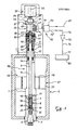
- FIG 1 there is shown schematically a milling machine 40 fixed to the ground 41 by screws 42.
- This milling machine comprises in particular a frame 43 supporting a work table 44 capable of being able to move in three coordinates X, Y, Z, l using, for example, electrical means moving endless screws not shown in the figure.
- An upper body 5 is integral with the frame 43 inside which is mounted an electrospindle 46 enclosing a tool holder 50 around an axis 22 and one end of which holds a tool 4 such as a milling cutter.
- Thrust means 30 represented by an electromechanical jack are disposed above the upper body supporting the electrospindle, coaxially with respect to the axis 22.
- a control unit 53 gives the various instructions necessary for the smooth running of the machine. tool (table movements, rotation, stopping the electrospindle, etc.).
- the work table 44 comprises for example clamps 54 allowing the attachment of a workpiece 55.
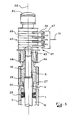
- FIG. 2 represents a section of a tool holder according to the prior art and its description will be made with that of FIGS. 3 and 4 which illustrate the tool holder according to the invention on the one hand in the working position or tool locking ( Figure 3) and secondly in the rest position or unlocking the tool ( Figure 4).
- This tool holder comprises a sheath 1 in which an axial through hole 2 is formed, defined by two coaxial bores 11 and 12 of different diameters, the bore 11 corresponding to that of smaller diameter.
- the change in diameter between these two bores 11 and 12 inside the sheath is represented by an internal shoulder 14; the bore 11 of this sleeve ends in a conical end 3 capable of receiving the corresponding conical part of the working tool 4.
- the sheath 1 is integrated in the body 5 (shown schematically in Figures 2,3 and 4) integral with the frame 43 of the machine tool.
- An electric motor 57 is arranged between the sheath 1 receiving the rotor 58, and the body 5 receiving the stator 59 of this motor.
- a rod 6 is arranged in the axial breakthrough 2, the diameter of which is substantially equivalent to the bore of smaller diameter 11. It has at its lower end 7, located in the vicinity of the conical end 3 of the sheath, gripping means 8 defined by a ring 15, a first end 16 of which is force fitted into a groove 17 formed in the rod 6 and the second end 18 of which is provided with resilient claws or clamps 19 projecting relative to the end 7 of the rod. These claws 19 are able to occupy two positions specified below.
- the rod 6 has at its opposite end 9 a thread 10.
- This rod is able to move axially relative to the sheath 1 between a first working position ( Figure 3) for which the claws 19 resiliently clamp the head 20 of the tool 4 and a second rest position ( Figure 4) for which the claws 19 are elastically spaced from one another, to release the head of the tool.
- These claws are then inserted into a notch 32 formed in the axial breakthrough 2, more precisely above the conical end 3 of the bore 11.
- the first working position corresponds to the locking of the tool and the second rest position corresponds to the unlocking of the tool.
- This tool holder 50 further comprises elastic return means 25 produced by a stack of spring washers of the "Belleville” or “Schnorr” type which bears, on the one hand, against the internal shoulder 14 and, on the other hand, against a tightening nut 26 screwed onto the thread 10 of the end 9 of the rod 6.
- the spring washers 25 and the nut 26 are arranged in the bore 12 of larger diameter of the breakthrough axial. These means 25 keep the rod 6 in its working position, by pulling the tool against the conical end 3 by means of the gripping means 8 disposed at the end 7 of the rod 6. These means 25 tend to compress the nut tightening 26 under the traction effect developed by the spring washers.
- means are provided for permanent control of the rod in its working position by measuring for this, the variation in the compression force of the nut, and more precisely, the variations in dimension of the nut which are proportional to the force exerted by the spring washers on the nut.
- the tightening nut 26 is made of a material having elastic characteristics liable to deform for low compressions, this material possibly being steel.
- control means comprise, for example, a sensor constituted by resistive strain gauges 60 arranged by bonding in a notch 27 formed on the nut 26, means of supply and electrical transmission 61, means of analysis signals 70 emitted by the gauges and means 80 for displaying the value of the force measured.
- the supply and transmission means 61 of the signals comprise a rotating collector 62 screwed into the end of the rod 6 by means of a tapped hole 63 formed on one face 64 of the collector, this face coming substantially into contact with the upper end of the nut 26.
- This collector briefly comprises a rotor 65 provided with brushes 66 cooperating with brush holders 67 arranged on the body 5.
- connection wires 68 it is connected to the strain gauges 60 using connection wires 68, while the brush holders 67 receiving the signals transmitted by the collector, are connected to the signal analysis means 70 by a link 71
- These analysis means 70 notably comprise a distributor 72 of the signals, selecting and processing the latter coming on the one hand from the general power supply 69 and on the other hand from the strain gauges 60 via the collector 62.
- the output 73 of the distributor is connected to the input 74 of an amplifier 75, the output 76 of which is connected to the input 77 of the display means 80 consisting of a digital type display, for example with light-emitting diodes.
- the value initially displayed is representative of the compression force of the nut 26 exerted on it by the spring washers 25.
- the manifold 62 has at its end 84, opposite that coming substantially opposite the nut 26 through its face 64, a ring 85 comprising a flange 86 capable of coming into contact with a position detector 87 integral with the body 5 of the machine tool, by means of a jack 30 of the electromechanical type.
- This last one is also fixed to the body 5, in the axis 22 of the electrospindle 46 and is therefore coaxial with the assembly of the sheath 1, the rod 6, the nut 26 and the manifold 62.
- the head of the piston of this jack is opposite the end 84 of the manifold.
- connection wires 68 connecting the gauges 60 to the manifold 62 are protected by a protective casing 90 mounted on the upper end of the sleeve 1 by screwing.
- the operator consults the value Vo indicated and delivered by the digital display 80 receiving the electrical information coming from the strain gauges 60 arranged by bonding on the nut and means of analysis 70 and transmission 61 of this signals. Beforehand, these various means will have been calibrated.
- the operator after having made the various adjustments for the machining of the part, activates the motor 57 of the electrospindle 46 thereby driving all of the sleeve 1, of the rod 6, of the nut 26 of the collector 62 and of the tool 4 rotating around the axis 22.
- the operator can control on the digital display 80, a possible variation of the value Vo initially displayed by means of the information transmitted by the strain gauges 60, permanently measuring the compression and the expansion of the part of the nut where they are bonded and representative of the force exerted on the bearing face of the tightening nut 26 by the stack of washers 25.
- the displayed value Vo is a maximum initial setting value, which can only decrease as a result of the fatigue and mechanical wear of the spring washers, of which the possible reduction in their effort is precisely measured.
- the digital display delivers a value lower than that of the reference (possibly supplemented by an audible or light signal) and intervene accordingly to change the spring washers.
- the mounting of the nut against the new set of spring washers in the bore 12 of the axial breakthrough 2 of the sheath 1 must be subjected beforehand to the control of its calibration indicating for example a value 0 in the display 80.
- the tightening of the nut 26 is carried out using the key until reaching the initial calibration value Vo.
- Disassembly of the tool according to the invention is carried out, using the electromechanical cylinder 30 actuated by the operator and the piston of which comes into contact with the end 84 of the manifold 62 driving down the assembly of the nut 26, the rod 6, and the tool 4 by compressing the spring washers 25.
- the force delivered by the jack is greater than that exerted by the spring washers.
- the claws 19 of the gripping means 8 move away gradually returning by elasticity to their original position to be housed in the notch 32 of the sheath 1 which remains fixed in translation relative to the axis 22.
- the operator removes the tool 4 from the tool holder to, for example, change the tools.
- the flange 86 of the ring 85 linked to the collector 62 is, during the descent of the assembly mentioned above, coming into contact with the position detector 87 secured to the body 5 thus causing the immobilization in rotation of the electrospindle as long as the tool holder is in the unlocked position.
- strain gauges it would be conceivable, without departing from the scope of the invention, to directly connect the strain gauges to the signal analysis means without passing through a collector in the case of a machine tool whose tool would work in translation.
Landscapes
- Engineering & Computer Science (AREA)
- Mechanical Engineering (AREA)
- Physics & Mathematics (AREA)
- General Physics & Mathematics (AREA)
- Gripping On Spindles (AREA)
- Machine Tool Sensing Apparatuses (AREA)
- Auxiliary Devices For Machine Tools (AREA)
- Jigs For Machine Tools (AREA)
Applications Claiming Priority (2)
| Application Number | Priority Date | Filing Date | Title |
|---|---|---|---|
| FR8515201 | 1985-10-14 | ||
| FR8515201A FR2588492B1 (fr) | 1985-10-14 | 1985-10-14 | Porte-outil de securite pour machine-outil |
Publications (2)
| Publication Number | Publication Date |
|---|---|
| EP0221802A1 true EP0221802A1 (de) | 1987-05-13 |
| EP0221802B1 EP0221802B1 (de) | 1989-04-05 |
Family
ID=9323801
Family Applications (1)
| Application Number | Title | Priority Date | Filing Date |
|---|---|---|---|
| EP86402184A Expired EP0221802B1 (de) | 1985-10-14 | 1986-10-03 | Sicherheitswerkzeughalter für Werkzeugmaschine |
Country Status (7)
| Country | Link |
|---|---|
| US (1) | US4708547A (de) |
| EP (1) | EP0221802B1 (de) |
| JP (1) | JPS6294207A (de) |
| CA (1) | CA1277490C (de) |
| DE (1) | DE3662655D1 (de) |
| ES (1) | ES2007565B3 (de) |
| FR (1) | FR2588492B1 (de) |
Cited By (4)
| Publication number | Priority date | Publication date | Assignee | Title |
|---|---|---|---|---|
| EP0258989A1 (de) * | 1986-07-24 | 1988-03-09 | Seiko Seiki Kabushiki Kaisha | Spannvorrichtung in einer Werkzeugmaschinenspindel |
| EP0356636A2 (de) * | 1988-09-02 | 1990-03-07 | Kelch Gmbh + Co. | Einzugskraft-Messgerät für Werkzeug-Spannvorrichtungen |
| FR2695850A1 (fr) * | 1992-09-23 | 1994-03-25 | Snecma | Appareil d'entraînement d'un outil rotatif permettant des changements d'outil faciles et installation comportant cet appareil. |
| WO1998004377A2 (de) * | 1996-07-25 | 1998-02-05 | Ima Montagetechnik Gmbh | Arbeitsspindel für eine werkzeugmaschine |
Families Citing this family (17)
| Publication number | Priority date | Publication date | Assignee | Title |
|---|---|---|---|---|
| EP0267156B1 (de) * | 1986-11-04 | 1994-12-07 | Fritz Krüsi Maschinenbau | Vorrichtung zum Bearbeiten eines Werkstückes aus Holz, insbesondere von Holzbalken |
| US5078558A (en) * | 1990-02-16 | 1992-01-07 | Hitachi Seiko, Ltd. | Low mass spindle and Z-axis unit |
| JP2001315010A (ja) * | 2000-05-08 | 2001-11-13 | Mori Seiki Co Ltd | 工作機械 |
| JP4772991B2 (ja) * | 2001-06-22 | 2011-09-14 | オークマ株式会社 | 工作機械の主軸装置 |
| EP1499472B2 (de) * | 2002-04-20 | 2014-10-15 | Renishaw plc | Maschinenanpassung |
| EP1398110B1 (de) * | 2002-09-13 | 2008-03-26 | Maschinenfabrik Berthold Hermle AG | Spindelkopf für eine Werkzeugmaschine |
| GB0311852D0 (en) * | 2003-05-22 | 2003-06-25 | Westwind Air Bearings Ltd | Rotary tool holder assemblies |
| DE102004011738B4 (de) * | 2004-03-03 | 2010-01-07 | Michael Weinig Ag | Vorrichtung mit einer Löseeinheit zum Betätigen einer Spannvorrichtung für Werkzeuge |
| US6951256B1 (en) * | 2004-04-24 | 2005-10-04 | Ru Song Xiao | Machine tool having coaxial driving device |
| DE102004026438B4 (de) * | 2004-05-29 | 2009-04-02 | Ott-Jakob Gmbh & Co. Spanntechnik Kg | Spannvorrichtung |
| DE102004051031B3 (de) * | 2004-10-20 | 2006-04-27 | Ott-Jakob Gmbh & Co. Spanntechnik Kg | Spannvorrichtung |
| RU2357345C2 (ru) * | 2006-10-11 | 2009-05-27 | Шлюмбергер Текнолоджи Б.В. | Погружной электрический двигатель постоянного тока |
| DE102007007389B3 (de) * | 2007-02-12 | 2008-07-03 | Ott-Jakob Spanntechnik Gmbh | Spannvorrichtung |
| DE102012005614B4 (de) | 2012-03-22 | 2013-10-17 | Matthias Brenneis | Sensorisches Verbindungselement und Herstellverfahren |
| JP5894837B2 (ja) * | 2012-04-02 | 2016-03-30 | トーヨーエイテック株式会社 | 工作機械のクランプ装置 |
| JP6492502B2 (ja) * | 2014-10-03 | 2019-04-03 | 株式会社ジェイテクト | 工作機械の主軸装置 |
| DE102020126006A1 (de) * | 2020-10-05 | 2022-04-07 | Sterman Technische Systeme Gmbh | Spannvorrichtung, Spindelanordnung sowie Werkzeugmaschine |
Citations (5)
| Publication number | Priority date | Publication date | Assignee | Title |
|---|---|---|---|---|
| US3201977A (en) * | 1961-02-20 | 1965-08-24 | Kutsay Ali Umit | Strain gauge |
| FR1451525A (fr) * | 1965-07-22 | 1966-01-07 | Forest & Cie | Dispositif de blocage d'un porte-outil conique dans un nez de broche rotative de machine-outil |
| FR2518749A1 (fr) * | 1981-12-23 | 1983-06-24 | Forkardt Paul Gmbh | Capteur de force de serrage pour dispositifs rotatifs de serrage |
| DE3212761A1 (de) * | 1982-04-06 | 1983-10-13 | Paul Forkardt GmbH & Co KG, 4000 Düsseldorf | Umlaufende spannvorrichtung |
| DE3408310A1 (de) * | 1984-03-07 | 1984-10-04 | Eberhard Dipl.-Ing. 6301 Wettenberg Seidel | Messvorrichtung zum getrennten messen der axialen spannkraft und des anziehdrehmomentes sowie dessen anteile aus gewinde- und kopfreibung einer schraubenverbindung ohne ueberlagerung von zug- und torsionsspannung |
Family Cites Families (7)
| Publication number | Priority date | Publication date | Assignee | Title |
|---|---|---|---|---|
| US3520228A (en) * | 1967-04-10 | 1970-07-14 | Giddings & Lewis | Spindle orienting and drawbolt malfunction sensing machine tool control system |
| US3603203A (en) * | 1970-01-12 | 1971-09-07 | Pratt & Whitney Inc | Pneumatic tool-sensing system for machine tool |
| SU524618A1 (ru) * | 1975-01-20 | 1976-08-15 | Устройство дл зажима интрумента в шпинделе станка | |
| JPS5245784A (en) * | 1975-10-09 | 1977-04-11 | Howa Mach Ltd | Unclampdevice for tool |
| US4303360A (en) * | 1980-02-29 | 1981-12-01 | Giddings & Lewis, Inc. | Power drawfinger system for machine tool spindle |
| JPS5924944A (ja) * | 1982-07-27 | 1984-02-08 | Yamazaki Mazak Corp | 工具保持力測定装置 |
| JPS5973252A (ja) * | 1982-10-20 | 1984-04-25 | Inoue Japax Res Inc | 工具及び工具取り付け装置 |
-
1985
- 1985-10-14 FR FR8515201A patent/FR2588492B1/fr not_active Expired
-
1986
- 1986-10-03 ES ES86402184T patent/ES2007565B3/es not_active Expired
- 1986-10-03 EP EP86402184A patent/EP0221802B1/de not_active Expired
- 1986-10-03 DE DE8686402184T patent/DE3662655D1/de not_active Expired
- 1986-10-09 JP JP61239427A patent/JPS6294207A/ja active Pending
- 1986-10-14 CA CA000520367A patent/CA1277490C/fr not_active Expired - Fee Related
- 1986-10-14 US US06/918,394 patent/US4708547A/en not_active Expired - Fee Related
Patent Citations (5)
| Publication number | Priority date | Publication date | Assignee | Title |
|---|---|---|---|---|
| US3201977A (en) * | 1961-02-20 | 1965-08-24 | Kutsay Ali Umit | Strain gauge |
| FR1451525A (fr) * | 1965-07-22 | 1966-01-07 | Forest & Cie | Dispositif de blocage d'un porte-outil conique dans un nez de broche rotative de machine-outil |
| FR2518749A1 (fr) * | 1981-12-23 | 1983-06-24 | Forkardt Paul Gmbh | Capteur de force de serrage pour dispositifs rotatifs de serrage |
| DE3212761A1 (de) * | 1982-04-06 | 1983-10-13 | Paul Forkardt GmbH & Co KG, 4000 Düsseldorf | Umlaufende spannvorrichtung |
| DE3408310A1 (de) * | 1984-03-07 | 1984-10-04 | Eberhard Dipl.-Ing. 6301 Wettenberg Seidel | Messvorrichtung zum getrennten messen der axialen spannkraft und des anziehdrehmomentes sowie dessen anteile aus gewinde- und kopfreibung einer schraubenverbindung ohne ueberlagerung von zug- und torsionsspannung |
Cited By (6)
| Publication number | Priority date | Publication date | Assignee | Title |
|---|---|---|---|---|
| EP0258989A1 (de) * | 1986-07-24 | 1988-03-09 | Seiko Seiki Kabushiki Kaisha | Spannvorrichtung in einer Werkzeugmaschinenspindel |
| EP0356636A2 (de) * | 1988-09-02 | 1990-03-07 | Kelch Gmbh + Co. | Einzugskraft-Messgerät für Werkzeug-Spannvorrichtungen |
| EP0356636A3 (de) * | 1988-09-02 | 1991-04-03 | Gmbh + Co. Kelch | Einzugskraft-Messgerät für Werkzeug-Spannvorrichtungen |
| FR2695850A1 (fr) * | 1992-09-23 | 1994-03-25 | Snecma | Appareil d'entraînement d'un outil rotatif permettant des changements d'outil faciles et installation comportant cet appareil. |
| WO1998004377A2 (de) * | 1996-07-25 | 1998-02-05 | Ima Montagetechnik Gmbh | Arbeitsspindel für eine werkzeugmaschine |
| WO1998004377A3 (de) * | 1996-07-25 | 1998-03-26 | Ima Montagetechnik Gmbh | Arbeitsspindel für eine werkzeugmaschine |
Also Published As
| Publication number | Publication date |
|---|---|
| DE3662655D1 (en) | 1989-05-11 |
| FR2588492A1 (fr) | 1987-04-17 |
| ES2007565B3 (es) | 1989-08-01 |
| EP0221802B1 (de) | 1989-04-05 |
| JPS6294207A (ja) | 1987-04-30 |
| CA1277490C (fr) | 1990-12-11 |
| FR2588492B1 (fr) | 1989-05-26 |
| US4708547A (en) | 1987-11-24 |
Similar Documents
| Publication | Publication Date | Title |
|---|---|---|
| EP0221802B1 (de) | Sicherheitswerkzeughalter für Werkzeugmaschine | |
| EP1120190B1 (de) | Pneumatische Werkzeugmaschine | |
| FR2859838A1 (fr) | Installation de limitation de couple pour un moteur electrique notamment un outil electroportatif | |
| FR2643845A3 (fr) | Tournevis | |
| FR2743449A1 (fr) | Outil portable pour le sertissage de broches de connexion sur des conducteurs electriques | |
| FR2468428A1 (fr) | Dispositif de fixation d'outil, notamment pour perceuse a main | |
| FR2773131A1 (fr) | Articulation a rotule pour direction de vehicule automobile | |
| FR2755049A1 (fr) | Serrage pilote compact | |
| FR2474375A1 (de) | ||
| WO2007031682A1 (fr) | Procede et dispositif de reglage de la profondeur d'emmanchement d'un outil dans un porte-outil | |
| FR2534515A1 (fr) | Ensemble porte-outil vibrant | |
| FR2474363A1 (fr) | Outil d'usinage avec brise-copeaux reglable | |
| FR2583520A1 (fr) | Detecteur de vitesse de vehicule automobile | |
| EP1252969B1 (de) | Antriebsschraubenmodul mit Stossdämpfung | |
| FR2776858A1 (fr) | Dispositif de maintien, de positionnement, ou de serrage, a actionnement electrique | |
| EP1157766B1 (de) | Stangenzuführvorrichtung | |
| EP2998835A1 (de) | Vorrichtung zur dateneingabe und seine bremsmittel | |
| EP1592534B1 (de) | Vorrichtung zum schleifen von ophthalmischen linsen mit verbessertem mittel zum festklemmen des glasrohlings zum schleifen | |
| FR2814765A1 (fr) | Systeme de commande de la meule d'une machine de meulage notamment de rails | |
| CH664516A5 (en) | Dental mandrel for boring or cutting - has central hole of chuck tilted obliquely by slide | |
| EP1890840A1 (de) | Kalibrierwerkzeug und dieses umfassende fräsmaschine | |
| FR2543041A1 (fr) | Procede et installation de serrage d'une liaison de type vis, avec controle de la tension mecanique appliquee a la vis | |
| EP0569288B1 (de) | Hubschrauberheckrotor mit einem Detektor der Überschreitung einer Verschiebungschwellenspannung in der Steigungsregelung | |
| FR2842449A1 (fr) | Dispositif et outil d'assemblage a sortie de donnees | |
| FR2814493A1 (fr) | Machine de forage ou de sondage equipee d'un systeme de securite |
Legal Events
| Date | Code | Title | Description |
|---|---|---|---|
| PUAI | Public reference made under article 153(3) epc to a published international application that has entered the european phase |
Free format text: ORIGINAL CODE: 0009012 |
|
| AK | Designated contracting states |
Kind code of ref document: A1 Designated state(s): BE DE ES GB IT NL |
|
| 17P | Request for examination filed |
Effective date: 19870529 |
|
| 17Q | First examination report despatched |
Effective date: 19880627 |
|
| GRAA | (expected) grant |
Free format text: ORIGINAL CODE: 0009210 |
|
| RAP1 | Party data changed (applicant data changed or rights of an application transferred) |
Owner name: SOCIETE NATIONALE INDUSTRIELLE AEROSPATIALE SOCIET |
|
| AK | Designated contracting states |
Kind code of ref document: B1 Designated state(s): BE DE ES GB IT NL |
|
| RAP2 | Party data changed (patent owner data changed or rights of a patent transferred) |
Owner name: AEROSPATIALE SOCIETE NATIONALE INDUSTRIELLE |
|
| REF | Corresponds to: |
Ref document number: 3662655 Country of ref document: DE Date of ref document: 19890511 |
|
| GBT | Gb: translation of ep patent filed (gb section 77(6)(a)/1977) | ||
| ITF | It: translation for a ep patent filed | ||
| BECN | Be: change of holder's name |
Effective date: 19890405 |
|
| PLBE | No opposition filed within time limit |
Free format text: ORIGINAL CODE: 0009261 |
|
| STAA | Information on the status of an ep patent application or granted ep patent |
Free format text: STATUS: NO OPPOSITION FILED WITHIN TIME LIMIT |
|
| 26N | No opposition filed | ||
| ITTA | It: last paid annual fee | ||
| PGFP | Annual fee paid to national office [announced via postgrant information from national office to epo] |
Ref country code: GB Payment date: 19921001 Year of fee payment: 7 |
|
| PGFP | Annual fee paid to national office [announced via postgrant information from national office to epo] |
Ref country code: ES Payment date: 19921005 Year of fee payment: 7 |
|
| PGFP | Annual fee paid to national office [announced via postgrant information from national office to epo] |
Ref country code: NL Payment date: 19921031 Year of fee payment: 7 |
|
| PGFP | Annual fee paid to national office [announced via postgrant information from national office to epo] |
Ref country code: DE Payment date: 19921104 Year of fee payment: 7 |
|
| PGFP | Annual fee paid to national office [announced via postgrant information from national office to epo] |
Ref country code: BE Payment date: 19921208 Year of fee payment: 7 |
|
| PG25 | Lapsed in a contracting state [announced via postgrant information from national office to epo] |
Ref country code: GB Effective date: 19931003 |
|
| PG25 | Lapsed in a contracting state [announced via postgrant information from national office to epo] |
Ref country code: ES Free format text: LAPSE BECAUSE OF THE APPLICANT RENOUNCES Effective date: 19931004 |
|
| PG25 | Lapsed in a contracting state [announced via postgrant information from national office to epo] |
Ref country code: BE Effective date: 19931031 |
|
| BERE | Be: lapsed |
Owner name: AEROSPATIALE SOC. NATIONALE INDUSTRIELLE Effective date: 19931031 |
|
| PG25 | Lapsed in a contracting state [announced via postgrant information from national office to epo] |
Ref country code: NL Effective date: 19940501 |
|
| GBPC | Gb: european patent ceased through non-payment of renewal fee |
Effective date: 19931003 |
|
| NLV4 | Nl: lapsed or anulled due to non-payment of the annual fee | ||
| PG25 | Lapsed in a contracting state [announced via postgrant information from national office to epo] |
Ref country code: DE Effective date: 19940701 |
|
| REG | Reference to a national code |
Ref country code: ES Ref legal event code: FD2A Effective date: 19991007 |
|
| PG25 | Lapsed in a contracting state [announced via postgrant information from national office to epo] |
Ref country code: IT Free format text: LAPSE BECAUSE OF NON-PAYMENT OF DUE FEES;WARNING: LAPSES OF ITALIAN PATENTS WITH EFFECTIVE DATE BEFORE 2007 MAY HAVE OCCURRED AT ANY TIME BEFORE 2007. THE CORRECT EFFECTIVE DATE MAY BE DIFFERENT FROM THE ONE RECORDED. Effective date: 20051003 |