EP0221477B1 - Rohrpostanlage - Google Patents
Rohrpostanlage Download PDFInfo
- Publication number
- EP0221477B1 EP0221477B1 EP86114811A EP86114811A EP0221477B1 EP 0221477 B1 EP0221477 B1 EP 0221477B1 EP 86114811 A EP86114811 A EP 86114811A EP 86114811 A EP86114811 A EP 86114811A EP 0221477 B1 EP0221477 B1 EP 0221477B1
- Authority
- EP
- European Patent Office
- Prior art keywords
- travel
- right angles
- narrow
- pneumatic
- pipe system
- Prior art date
- Legal status (The legal status is an assumption and is not a legal conclusion. Google has not performed a legal analysis and makes no representation as to the accuracy of the status listed.)
- Expired
Links
- 238000007789 sealing Methods 0.000 claims abstract description 47
- 239000000969 carrier Substances 0.000 claims abstract 6
- 239000007787 solid Substances 0.000 description 3
- IHQKEDIOMGYHEB-UHFFFAOYSA-M sodium dimethylarsinate Chemical class [Na+].C[As](C)([O-])=O IHQKEDIOMGYHEB-UHFFFAOYSA-M 0.000 description 2
- 238000005299 abrasion Methods 0.000 description 1
- 230000000694 effects Effects 0.000 description 1
- 238000009434 installation Methods 0.000 description 1
- 230000001788 irregular Effects 0.000 description 1
- 239000000463 material Substances 0.000 description 1
- 230000001105 regulatory effect Effects 0.000 description 1
Images



Classifications
-
- B—PERFORMING OPERATIONS; TRANSPORTING
- B65—CONVEYING; PACKING; STORING; HANDLING THIN OR FILAMENTARY MATERIAL
- B65G—TRANSPORT OR STORAGE DEVICES, e.g. CONVEYORS FOR LOADING OR TIPPING, SHOP CONVEYOR SYSTEMS OR PNEUMATIC TUBE CONVEYORS
- B65G51/00—Conveying articles through pipes or tubes by fluid flow or pressure; Conveying articles over a flat surface, e.g. the base of a trough, by jets located in the surface
- B65G51/04—Conveying the articles in carriers having a cross-section approximating that of the pipe or tube; Tube mail systems
- B65G51/06—Despatch carriers for tube mail
-
- B—PERFORMING OPERATIONS; TRANSPORTING
- B65—CONVEYING; PACKING; STORING; HANDLING THIN OR FILAMENTARY MATERIAL
- B65G—TRANSPORT OR STORAGE DEVICES, e.g. CONVEYORS FOR LOADING OR TIPPING, SHOP CONVEYOR SYSTEMS OR PNEUMATIC TUBE CONVEYORS
- B65G51/00—Conveying articles through pipes or tubes by fluid flow or pressure; Conveying articles over a flat surface, e.g. the base of a trough, by jets located in the surface
- B65G51/04—Conveying the articles in carriers having a cross-section approximating that of the pipe or tube; Tube mail systems
- B65G51/18—Adaptations of pipes or tubes; Pipe or tube joints
Definitions
- the invention relates to a pneumatic tube system with a pipeline system, with pneumatic tube bushes guided in an airtight manner in the tube system and with a suction / pressure blower for generating an overpressure or underpressure in the tube system, the inner cross section of the tube system and the outline of the pneumatic tube bushes being rectangular perpendicular to the direction of travel and the pneumatic post rifles are cuboid with a broad side and a narrow side, the outline of the cuboid perpendicular to the direction of travel is also smaller than the internal cross section and the cuboid is provided perpendicular to the direction of travel with circumferential sealing profiles which are spherical in the direction of travel.
- Such a pneumatic tube system is known from GB-B 1 338 051.
- the well-known pneumatic tube system is intended to connect a customer counter in a bank with a central cash register system.
- a pneumatic tube line with a rectangular cross section is provided, which connects the two stations in wide arches.
- note tube mail systems are known, for example, from US-A-3 888 433, US-A-1 951 820 and DE-A-323 886.
- paper tube mail systems instead of relatively bulky cuboid tube boxes, only individual pieces of paper, bundles of paper or, if necessary, narrow cardboard boxes are conveyed, which are provided with wings that protrude laterally obliquely at the front end and thus fill the relatively flat rectangular pipes.
- DD-A-67 927 describes another special elbow for pneumatic tube systems, but with cylindrical tubes.
- a pipe with a larger diameter is used in this special elbow, which must be connected to the further pipes at the connection points of the elbow via conical connecting parts.
- EP-A-0 034 940 also describes a pneumatic tube system with cuboid pneumatic tube bushes, but special components with an irregular course of the side walls are also used as manifolds in this known pneumatic tube system in order to counter the already mentioned problems with manifolds with a small radius of curvature.
- the invention is based on the object to further develop a pneumatic tube system of the type mentioned in such a way that manifolds with smaller radii of curvature can be used without the need for expensive and complex special components with complicated shapes, which are also due to their discontinuous course bring bad driving characteristics (driving noise) with it.
- the sealing profiles have circular cylindrical surfaces at least in sections and penetrate at their ends in the area of the corners, that a narrow section of the sealing profile arranged on the narrow side has a radius of curvature which is equal to half the inside width of the inner cross section in the width direction is perpendicular to the direction of travel and that a broad section of the sealing profile arranged on the broad side has a surface radius of curvature which is equal to half the clear width of the inner cross section in the width direction perpendicular to the direction of travel and that a broad section of the sealing profile arranged on the broad side has a surface radius of curvature which is equal to half the inside width of the inner cross section in the narrow direction perpendicular to the direction of travel.
- the object on which the invention is based is thus completely achieved because, owing to the shape of the pneumatic tube bushes described above, radii of curvature for the manifolds are possible which could not be achieved in such a small size in the prior art. It is particularly advantageous that as a crumb mer normal pipeline components can be used, in which the side walls of the elbows all run parallel to each other, so that complicated and complex shapes are unnecessary.
- Another advantage is that excessive friction when driving through bends in the overhead line system due to jams is reliably avoided. If the geometrical center point of all radii of the circular-cylindrical curved surfaces of the sections of the sealing profile lies in the plane of symmetry of the cuboid pneumatic tube, this means that the surface always has a common tangent with the inner surface of a curved inner surface of a pipe bend, namely because the radius of the bend also is aligned with the radius of the surface of the sealing profile.
- the circumferential sealing profiles can in principle be solid with a continuous circular cylindrical surface, but in a preferred embodiment of the invention the sealing profiles consist of a group of parallel and spaced apart individual sealing profiles, the surfaces of which lie on a circular cylindrical envelope.
- This measure has the advantage that the sealing profiles are even more flexible in themselves because the individual sealing profiles can dodge better in the event of frontal or oblique lateral stress.
- the weight of the pneumatic tube can is also reduced in this exemplary embodiment of the invention, which benefits the transport speed or the transportable payload of the pneumatic tube.
- sealing profiles are arranged symmetrically to the center lines of the broad side and the narrow side and if the cuboid pneumatic tube bushing is provided with two circumferential sealing profiles one behind the other in the direction of travel.
- the first-mentioned measure has the advantage that, in the case of a conventional, symmetrically curved pipe bend, completely identical conditions occur on the inner and the outer curved pipe wall, only mirrored in a point-symmetrical manner.
- the second-mentioned measure known per se has the advantage, which is also known per se, that the pneumatic tube bushing is guided securely in the pipeline sections.
- an embodiment of the invention is preferred in which the piping system has narrow elbows with a curved narrow side and wide elbows with a curved broad side and in which the radii of curvature of the center lines of the elbows are the same size.
- This measure has the advantage that when driving through narrow and wide manifolds largely the same driving conditions result, so that the loads on the pneumatic tube bushing are largely the same and this also results in a low level of noise when driving through the manifold. It is also ensured that the long side of the pneumatic tube can is at the same minimum distance from the inner walls of the pipeline system in both elbows, so that an optimal cross-sectional utilization is available.
- FIG. 1 designates a pneumatic tube system according to the invention.
- a pneumatic mailbox 11 can, as indicated by arrows 12 and 13, be moved in different directions in a pipeline system.
- the pneumatic tube bush 11 has a substantially cuboid shape and its outline, viewed in the direction of the arrows 12, 13, is rectangular with a different length of the rectangular sides.
- the pneumatic tube system consists, on the one hand, of straight line pieces 14 with an inner cross section which is also rectangular to the direction of travel.
- the pipeline system has narrow elbows 15, in which the narrow side is curved, and wide elbows 16, in which the broad side is curved.
- Station 17 there is a Station 17 indicated, with which pneumatic tube bushes 11 can be extended and retracted or redirected.
- the pneumatic tube system 10 finally also includes a blower 18 with which positive or negative pressure can be generated in the pipeline system in order to convey the pneumatic tube bushing 11.
- FIG. 1 is extremely schematic and further units known per se, in particular regulating and control units, are not shown for the sake of clarity.
- FIG. 2 shows the details of the pneumatic tube bushing 11 in a perspective representation and on an enlarged scale.
- the pneumatic tube bushing 11 comprises a cuboid box 20 which is provided on one end face with a cover 21 for inserting or removing items to be transported. Because of the cuboid shape of the box 20, the pneumatic tube bushing 11 is particularly suitable for conveying extensive and non-rollable documents.
- the box 20 alone, seen transversely to the direction of travel, has an outline which is smaller than the clear internal cross section of the piping system.
- two circumferential sealing profiles 22, 23 arranged one behind the other in the direction of travel are provided, the thickness of which is dimensioned such that the sealing profiles 22, 23 fill the space between the box 20 and the inner surfaces of the piping system .
- the sealing profiles 22, 23 have wide sections 26, 28 and narrow sections 27, 29 which span a broad side 24 or a narrow side 25 of the box 20.
- the surface of the sections 26 to 29 is circular cylindrical at least in sections, so that the ends of the sections 26 to 29 penetrate in the region of longitudinal corners 31, 32, 33, which form the broad sides 24 with the narrow sides 25 of the box 20, as with 34 and 35 indicated.
- the circular cylindrical surface shape of the sections 26 to 29 can be drawn down to the broad sides 24 or narrow sides 25, but it is also possible to provide shoulders 30 in order to achieve a corresponding overall height of the sections 26 to 29.
- 3 and 4 show the position of the pneumatic tube bushing 11 in the straight line piece 14 in two views.
- the pneumatic tube bushing 11 lies along lines 40, 41, 42, 43 on inner surfaces 50, 51 of the narrow side or the broad side of the straight line pieces 14.
- the distances between the narrow side 25 and the broad side 24 from the inner surface 50 of the narrow side and the inner surface 51 of the broad side of the line piece 14 are also denoted by H and h.
- the distances H and h are, as will be seen from FIGS. 5 and 6, dimensioned such that the elbows 15, 16 of the piping system can be safely passed through without the inner walls 50, 51 the narrow side 25 or the broad side 24 touch.
- the sealing profiles 22, 23 can either be formed in one piece with the box 20, but they can also be glued, welded or the like. Furthermore, it is possible to produce the sealing profiles 22, 23 from a particularly suitable material that on the one hand it is so pliable that it ensures a sufficient sealing effect even when the elbows 15, 16 are being driven through, but on the other hand it is also sufficiently resistant to abrasion.
- a sealing profile 48 is designed as an insert in a recess 49 of the box 20, the box 20 being curved per se in the region of the sealing profile 48.
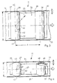
- FIG. 5 shows the pneumatic tube bush 11, in a view similar to FIG. 3, as it passes through the narrow elbow 15.
- the center line of the narrow elbow 15 is denoted by 55 and 56 is the radius of the curvature, which is indicated by a shortened center 57 going out.
- the contact lines 42 'and 42a' intersect in the center 57. This is because the contact lines 42 ', 42a' continue through the intersection 46 of the center line 55 of the narrow elbow 15 with the center line 44 of the broad side 24 of the Pneumatic tube rifle 11 go. Since the intersection 46 is also the starting point of the radius R, the narrow section 27 and the inner surface 50 of the narrow side of the narrow bend 15 touch in a common tangential plane.
- the radius 61 starting from a center 62 is a center line 60 of the wide elbow 16 as long as the corresponding radius of curvature 56 of the narrow elbow 15 in FIG. 5.
- single sealing profiles 70, 71, 72 are used instead of the solid sealing profiles, which, for example, can be inserted, glued, welded or the like into circumferential grooves 73 of the pneumatic tube bush 11, but of course also on the surface, for example the broad side 24, can be glued on, welded on, shrunk on, screwed on or the like.
- the individual sealing profiles 70, 71, 72 each have a surface that lies on a semi-cylindrical envelope curve 74, as was also the case with the solid sealing profiles 22, 23, 48 of the previously described exemplary embodiments .
- the radius of curvature r of the envelope 74 also coincides with the radius of curvature r of FIG. 4.
Landscapes
- Physics & Mathematics (AREA)
- Engineering & Computer Science (AREA)
- Fluid Mechanics (AREA)
- Mechanical Engineering (AREA)
- Actuator (AREA)
- Air Transport Of Granular Materials (AREA)
- Joints Allowing Movement (AREA)
- Jet Pumps And Other Pumps (AREA)
Priority Applications (1)
| Application Number | Priority Date | Filing Date | Title |
|---|---|---|---|
| AT86114811T ATE40872T1 (de) | 1985-10-28 | 1986-10-24 | Rohrpostanlage. |
Applications Claiming Priority (2)
| Application Number | Priority Date | Filing Date | Title |
|---|---|---|---|
| DE19853538241 DE3538241A1 (de) | 1985-10-28 | 1985-10-28 | Rohrpostanlage |
| DE3538241 | 1985-10-28 |
Publications (2)
| Publication Number | Publication Date |
|---|---|
| EP0221477A1 EP0221477A1 (de) | 1987-05-13 |
| EP0221477B1 true EP0221477B1 (de) | 1989-02-22 |
Family
ID=6284615
Family Applications (1)
| Application Number | Title | Priority Date | Filing Date |
|---|---|---|---|
| EP86114811A Expired EP0221477B1 (de) | 1985-10-28 | 1986-10-24 | Rohrpostanlage |
Country Status (3)
| Country | Link |
|---|---|
| EP (1) | EP0221477B1 (cg-RX-API-DMAC7.html) |
| AT (1) | ATE40872T1 (cg-RX-API-DMAC7.html) |
| DE (2) | DE3538241A1 (cg-RX-API-DMAC7.html) |
Families Citing this family (2)
| Publication number | Priority date | Publication date | Assignee | Title |
|---|---|---|---|---|
| CN108674994B (zh) * | 2018-06-25 | 2024-05-17 | 中国联合网络通信有限公司彭水县分公司 | 启闭装置 |
| CN114476683B (zh) * | 2020-11-11 | 2023-12-15 | 韦氏(苏州)医疗科技有限公司 | 气动物流传输系统 |
Family Cites Families (6)
| Publication number | Priority date | Publication date | Assignee | Title |
|---|---|---|---|---|
| DE323886C (de) * | 1918-03-31 | 1920-08-11 | Zwietusch E & Co Gmbh | Rohrkruemmung fuer Zettelrohrpostanlagen |
| US1951820A (en) * | 1930-11-14 | 1934-03-20 | Lamson Co | Pneumatic dispatch tube |
| GB1338051A (en) * | 1972-05-12 | 1973-11-21 | Lamson Engineering Co | Pneumatic tube systems |
| US3888433A (en) * | 1974-03-29 | 1975-06-10 | Bank Computer Network Corp | Disposable carriers for pneumatic conveyors |
| EP0034940B1 (en) * | 1980-02-25 | 1984-03-14 | D D Lamson Limited | Pneumatic tube carrier system |
| US4557638A (en) * | 1984-04-06 | 1985-12-10 | Neill Paul J O | Pneumatic tube conveyor |
-
1985
- 1985-10-28 DE DE19853538241 patent/DE3538241A1/de active Granted
-
1986
- 1986-10-24 EP EP86114811A patent/EP0221477B1/de not_active Expired
- 1986-10-24 DE DE8686114811T patent/DE3662133D1/de not_active Expired
- 1986-10-24 AT AT86114811T patent/ATE40872T1/de active
Also Published As
| Publication number | Publication date |
|---|---|
| DE3538241C2 (cg-RX-API-DMAC7.html) | 1989-01-12 |
| DE3538241A1 (de) | 1987-05-07 |
| ATE40872T1 (de) | 1989-03-15 |
| DE3662133D1 (en) | 1989-03-30 |
| EP0221477A1 (de) | 1987-05-13 |
Similar Documents
| Publication | Publication Date | Title |
|---|---|---|
| EP2281138B1 (de) | Strömungsoptimierter rohrbogen | |
| DE2655580A1 (de) | Transportsystem fuer flaches foerdergut | |
| EP0166800B1 (de) | Kopfstück für Betankungssysteme | |
| DE2731692A1 (de) | Verfahren und vorrichtung zur pneumatischen foerderung | |
| EP0166799A1 (de) | Betankungssystem, insbesondere für die Flugzeugbetankung | |
| DE69108881T2 (de) | Mechanismus zur Reduzierung von Druckverlusten in Rohrkrümmern. | |
| EP0221477A1 (de) | Rohrpostanlage | |
| US4557638A (en) | Pneumatic tube conveyor | |
| DE2809666C2 (cg-RX-API-DMAC7.html) | ||
| DE4124156C1 (cg-RX-API-DMAC7.html) | ||
| EP1042202B1 (de) | Schienenführbares fördermittel und führungsschiene zum führen des fördermittels | |
| DE2251108C3 (de) | Vorrichtung zum Überführen von schuppenförmig geförderten flachen Werkstücken, insbesondere von schlauchförmigen Faltschachtel-Zuschnitten von einer geschuppten Längslage in eine geschuppte Querlage | |
| EP0469636A2 (de) | Vorrichtung zum Wenden eines Produktstroms | |
| EP0091557B1 (de) | Vorrichtung zum Herstellen einer Verbindung zwischen jeweils zwei von mehreren Stationen | |
| DE68917390T2 (de) | Vorrichtung zum drucklosen Ausrichten von verschiedenen Gegenständen, insbesondere von Flaschen. | |
| EP0331099B1 (de) | Rohraggregat für die Aufnahme von Kabeln | |
| DE10159827B4 (de) | Rohrweiche für ein pneumatisches Fördersystem | |
| DE102017205071B4 (de) | Umlenk-Rohrelement für eine pneumatische Schüttgut-Fördereinrichtung | |
| DE8530464U1 (de) | Rohrpostbüchse | |
| DE69704116T2 (de) | Rohrverbinder für röhren in denen eine kabelinstallation vorgesehen ist | |
| DE4124913C2 (de) | Kontaktflächen eines Gleisbauteils wie Schiene oder Weichenbauteil und eines auf diesem fahrenden Rades eines Schienenfahrzeuges | |
| DE2938746C2 (de) | Ventilvorrichtung an einem Saugluftförderer | |
| DE3240894C2 (de) | Pneumatische Transportvorrichtung | |
| EP0611256A1 (de) | Transportsystem mit Transportketten | |
| EP1355012A2 (de) | Bausatz mit Eckverbinder |
Legal Events
| Date | Code | Title | Description |
|---|---|---|---|
| PUAI | Public reference made under article 153(3) epc to a published international application that has entered the european phase |
Free format text: ORIGINAL CODE: 0009012 |
|
| AK | Designated contracting states |
Kind code of ref document: A1 Designated state(s): AT CH DE FR GB IT LI NL |
|
| 17P | Request for examination filed |
Effective date: 19870827 |
|
| 17Q | First examination report despatched |
Effective date: 19880425 |
|
| GRAA | (expected) grant |
Free format text: ORIGINAL CODE: 0009210 |
|
| AK | Designated contracting states |
Kind code of ref document: B1 Designated state(s): AT CH DE FR GB IT LI NL |
|
| REF | Corresponds to: |
Ref document number: 40872 Country of ref document: AT Date of ref document: 19890315 Kind code of ref document: T |
|
| REF | Corresponds to: |
Ref document number: 3662133 Country of ref document: DE Date of ref document: 19890330 |
|
| GBT | Gb: translation of ep patent filed (gb section 77(6)(a)/1977) | ||
| ITF | It: translation for a ep patent filed | ||
| ET | Fr: translation filed | ||
| PLBE | No opposition filed within time limit |
Free format text: ORIGINAL CODE: 0009261 |
|
| STAA | Information on the status of an ep patent application or granted ep patent |
Free format text: STATUS: NO OPPOSITION FILED WITHIN TIME LIMIT |
|
| 26N | No opposition filed | ||
| ITTA | It: last paid annual fee | ||
| REG | Reference to a national code |
Ref country code: CH Ref legal event code: PUE Owner name: TECHNO MARK AG |
|
| REG | Reference to a national code |
Ref country code: FR Ref legal event code: TP |
|
| REG | Reference to a national code |
Ref country code: GB Ref legal event code: 732E |
|
| ITPR | It: changes in ownership of a european patent |
Owner name: CESSIONE;TECHNO MARK AG |
|
| NLS | Nl: assignments of ep-patents |
Owner name: TECHNO MARK AG TE ROTKREUZ, ZWITSERLAND. |
|
| PGFP | Annual fee paid to national office [announced via postgrant information from national office to epo] |
Ref country code: FR Payment date: 19960923 Year of fee payment: 11 |
|
| PGFP | Annual fee paid to national office [announced via postgrant information from national office to epo] |
Ref country code: GB Payment date: 19960924 Year of fee payment: 11 |
|
| PGFP | Annual fee paid to national office [announced via postgrant information from national office to epo] |
Ref country code: NL Payment date: 19960926 Year of fee payment: 11 |
|
| PGFP | Annual fee paid to national office [announced via postgrant information from national office to epo] |
Ref country code: AT Payment date: 19960927 Year of fee payment: 11 |
|
| PGFP | Annual fee paid to national office [announced via postgrant information from national office to epo] |
Ref country code: CH Payment date: 19961003 Year of fee payment: 11 |
|
| PGFP | Annual fee paid to national office [announced via postgrant information from national office to epo] |
Ref country code: DE Payment date: 19961211 Year of fee payment: 11 |
|
| PG25 | Lapsed in a contracting state [announced via postgrant information from national office to epo] |
Ref country code: GB Free format text: LAPSE BECAUSE OF NON-PAYMENT OF DUE FEES Effective date: 19971024 Ref country code: AT Free format text: LAPSE BECAUSE OF NON-PAYMENT OF DUE FEES Effective date: 19971024 |
|
| PG25 | Lapsed in a contracting state [announced via postgrant information from national office to epo] |
Ref country code: LI Free format text: LAPSE BECAUSE OF NON-PAYMENT OF DUE FEES Effective date: 19971031 Ref country code: FR Free format text: THE PATENT HAS BEEN ANNULLED BY A DECISION OF A NATIONAL AUTHORITY Effective date: 19971031 Ref country code: CH Free format text: LAPSE BECAUSE OF NON-PAYMENT OF DUE FEES Effective date: 19971031 |
|
| PG25 | Lapsed in a contracting state [announced via postgrant information from national office to epo] |
Ref country code: NL Free format text: LAPSE BECAUSE OF NON-PAYMENT OF DUE FEES Effective date: 19980501 |
|
| REG | Reference to a national code |
Ref country code: CH Ref legal event code: PL |
|
| GBPC | Gb: european patent ceased through non-payment of renewal fee |
Effective date: 19971024 |
|
| NLV4 | Nl: lapsed or anulled due to non-payment of the annual fee |
Effective date: 19980501 |
|
| PG25 | Lapsed in a contracting state [announced via postgrant information from national office to epo] |
Ref country code: DE Free format text: LAPSE BECAUSE OF NON-PAYMENT OF DUE FEES Effective date: 19980701 |
|
| REG | Reference to a national code |
Ref country code: FR Ref legal event code: ST |
|
| PG25 | Lapsed in a contracting state [announced via postgrant information from national office to epo] |
Ref country code: IT Free format text: LAPSE BECAUSE OF NON-PAYMENT OF DUE FEES;WARNING: LAPSES OF ITALIAN PATENTS WITH EFFECTIVE DATE BEFORE 2007 MAY HAVE OCCURRED AT ANY TIME BEFORE 2007. THE CORRECT EFFECTIVE DATE MAY BE DIFFERENT FROM THE ONE RECORDED. Effective date: 20051024 |