EP0220699B1 - Feeding carriage for a battery cage of several stories - Google Patents
Feeding carriage for a battery cage of several stories Download PDFInfo
- Publication number
- EP0220699B1 EP0220699B1 EP86114832A EP86114832A EP0220699B1 EP 0220699 B1 EP0220699 B1 EP 0220699B1 EP 86114832 A EP86114832 A EP 86114832A EP 86114832 A EP86114832 A EP 86114832A EP 0220699 B1 EP0220699 B1 EP 0220699B1
- Authority
- EP
- European Patent Office
- Prior art keywords
- feed
- cage
- funnel
- chute
- wall
- Prior art date
- Legal status (The legal status is an assumption and is not a legal conclusion. Google has not performed a legal analysis and makes no representation as to the accuracy of the status listed.)
- Expired
Links
- 244000144977 poultry Species 0.000 abstract 1
- 241001465754 Metazoa Species 0.000 description 2
- 230000005540 biological transmission Effects 0.000 description 2
- 230000000694 effects Effects 0.000 description 2
- 239000003245 coal Substances 0.000 description 1
- 238000010276 construction Methods 0.000 description 1
- 238000006073 displacement reaction Methods 0.000 description 1
- 238000012423 maintenance Methods 0.000 description 1
- 239000000463 material Substances 0.000 description 1
- 238000000034 method Methods 0.000 description 1
Images


Classifications
-
- B—PERFORMING OPERATIONS; TRANSPORTING
- B65—CONVEYING; PACKING; STORING; HANDLING THIN OR FILAMENTARY MATERIAL
- B65G—TRANSPORT OR STORAGE DEVICES, e.g. CONVEYORS FOR LOADING OR TIPPING, SHOP CONVEYOR SYSTEMS OR PNEUMATIC TUBE CONVEYORS
- B65G11/00—Chutes
- B65G11/20—Auxiliary devices, e.g. for deflecting, controlling speed of, or agitating articles or solids
- B65G11/206—Auxiliary devices, e.g. for deflecting, controlling speed of, or agitating articles or solids for bulk
-
- A—HUMAN NECESSITIES
- A01—AGRICULTURE; FORESTRY; ANIMAL HUSBANDRY; HUNTING; TRAPPING; FISHING
- A01K—ANIMAL HUSBANDRY; AVICULTURE; APICULTURE; PISCICULTURE; FISHING; REARING OR BREEDING ANIMALS, NOT OTHERWISE PROVIDED FOR; NEW BREEDS OF ANIMALS
- A01K31/00—Housing birds
- A01K31/14—Nest-boxes, e.g. for singing birds or the like
- A01K31/16—Laying nests for poultry; Egg collecting
- A01K31/17—Laying batteries including auxiliary features, e.g. feeding, watering, demanuring, heating, ventilation
-
- A—HUMAN NECESSITIES
- A01—AGRICULTURE; FORESTRY; ANIMAL HUSBANDRY; HUNTING; TRAPPING; FISHING
- A01K—ANIMAL HUSBANDRY; AVICULTURE; APICULTURE; PISCICULTURE; FISHING; REARING OR BREEDING ANIMALS, NOT OTHERWISE PROVIDED FOR; NEW BREEDS OF ANIMALS
- A01K39/00—Feeding or drinking appliances for poultry or other birds
- A01K39/01—Feeding devices, e.g. chainfeeders
Definitions
- the invention relates to a feed wagon for a multi-day cage battery, with a feed container, a height conveyor for the feed, which has discharge openings assigned to the different cage levels, and with adjustable discharge funnels, each of which extends downward from a discharge opening and in operation into the associated floor trough the cage battery.
Landscapes
- Life Sciences & Earth Sciences (AREA)
- Environmental Sciences (AREA)
- Birds (AREA)
- Animal Husbandry (AREA)
- Biodiversity & Conservation Biology (AREA)
- Zoology (AREA)
- Feeding And Watering For Cattle Raising And Animal Husbandry (AREA)
- Filling Or Emptying Of Bunkers, Hoppers, And Tanks (AREA)
- Specific Conveyance Elements (AREA)
- Intermediate Stations On Conveyors (AREA)
- Housing For Livestock And Birds (AREA)
Abstract
Description
Die Erfindung betrifft einen Futterwagen für eine mehretagige Käfigbatterie, mit einem Futterbehälter, einem Höhenförderer für das Futter, der den verschiedenen Käfigetagen zugeordnete Abgabeöffnungen aufweist, und mit verstellbaren Auslauftrichtern, die sich jeweils von einer Abgabeöffnung abwärts geneigt erstrecken und im Betrieb bis in den zugehörigen Etagentrog der Käfigbatterie herabragen.The invention relates to a feed wagon for a multi-day cage battery, with a feed container, a height conveyor for the feed, which has discharge openings assigned to the different cage levels, and with adjustable discharge funnels, each of which extends downward from a discharge opening and in operation into the associated floor trough the cage battery.
Ein solcher Futterwagen ist bekannt (DE-U-74 13 448). Dieser bekannte Futterwagen ist für eine Käfigbatterie mit rückseitig aneinander anschließenden Doppelkäfigen vorgesehen, die auf den einander gegenüberliegenden Längsseiten mit waagerechten Trögen versehen sind. Der Futterwagen übergreift die Käfigbatterie, weist auf dessen sich gegenüberliegenden Längsseiten jeweils einen Futterbehälter mit einem Höhenförderer und mit Auslauftrichtern auf und ist auf zwei Laufschienen in Längsrichtung verfahrbar. Somit wird jeder Trog bei einem Durchlauf des Futterwagens vom einen zum anderen Ende der Käfigbatterie auf seiner ganzen Länge mit Futter beschickt.Such a feed wagon is known (DE-U-74 13 448). This known feed wagon is provided for a cage battery with double cages adjoining one another on the back, which are provided with horizontal troughs on the opposite longitudinal sides. The feed wagon overlaps the cage battery, has a feed container with a height conveyor and discharge funnels on each of its opposite long sides and can be moved in the longitudinal direction on two running rails. This means that each trough is fed with feed along its entire length as the feed wagon passes from one end to the other of the cage battery.
Diese direkte Futterzuführung an alle Stellen des Troges begünstigt eine qualitativ gleichmäßige Fütterung aller Tiere, die dann nicht gewährleistet ist, wenn ein längsgerichteter Futtertransport durch den Trog stattfindet, weil dann bei einem Mischfutter bestimmte Futteranteile bevorzugt von den Tieren weggepickt werden, so daß das Futter an den in Transportrichtung nachfolgenden Stellen nicht mehr in der vorgesehenen Zusammensetzung ankommt. Außerdem hat ein sich durch den Trog erstreckendes Transportorgan wie eine Kette oder dergleichen den Nachteil, daß trotz mengenmäßig richtiger Fütterung Futterreste für längere Zeit im Trog verbleiben, was zu einer Qualitätsminderung des Futter führt.This direct feed to all parts of the trough favors a qualitatively uniform feeding of all animals, which is not guaranteed if a longitudinal feed transport takes place through the trough, because then in a mixed feed certain feed portions are preferably picked by the animals, so that the feed is on the places following in the direction of transport no longer arrive in the intended composition. In addition, a transport member extending through the trough, such as a chain or the like, has the disadvantage that, in spite of the correct amount of feeding, feed residues remain in the trough for a long time, which leads to a reduction in the quality of the feed.
Ein Nachteil der bekannten Futterzuführung mittels verfahrbarer Auslauftrichter liegt jedoch darin, daß es zu einer ungleichmäßigen Trogbefüllung bzw. zu Futterlücken im Trog kommt wenn sich das Futter auch nur kurzzeitig durch Brückenbildung oder dergleichen im Auslauftrichter staut. Dieser Gefahr wird beim bekannten Futterwagen dadurch begegnet, daß innerhalb eines jeden Auslauftrichters ein Drahtrahmen aufgehängt ist, der bis nahe zur Bodenöffnung des Auslauftrichters herabreicht und über einen aus dem Auslauftrichter nach außen geführten Doppelhebel und ein an diesen angreifendes Gestänge von einem Exzenter im wesentlichen vertikal hin und her bewegbar ist. Diese Rütteleinrichtung verhindert zwar Brückenbildungen im Auslauftrichter und sichert dadurch eine kontinuierliche Futterabgabe, erfordert aber einen entsprechenden Aufwand. Insbesondere sind auch die innerhalb der Auslauftrichter angeordneten Teile und Lager oder Gelenkstellen schlecht zugänglich, was angesichts der Rüttelbeanspruchung und des damit verbundenen Verschließes sowie im Hinblick auf die Anordnung im Futterstrom ungünstig ist.A disadvantage of the known feed supply by means of a movable discharge hopper is, however, that there is an uneven trough filling or feed gaps in the trough if the feed accumulates even briefly in the discharge hopper due to bridging or the like. This danger is countered in the known feed wagon in that a wire frame is suspended within each discharge funnel, which extends down to almost the bottom opening of the discharge funnel and via a double lever led out of the discharge funnel and a linkage attacking it from an eccentric substantially vertically and can be moved here. Although this vibrating device prevents bridges from forming in the discharge funnel and thereby ensures a continuous feed delivery, it requires a corresponding effort. In particular, the parts and bearings or articulation points arranged within the discharge funnel are also difficult to access, which is unfavorable in view of the vibrating stress and the associated closure and in view of the arrangement in the feed stream.
Dementsprechend liegt der Erfindung die Aufgabe zugrunde, die kontinuierliche Futterabgabe durch die Auslauftrichter in einer Weise sicherzustellen, die weder einen größeren konstruktiven Aufwand erfordert noch verschleiß- und wartungsintensiv ist.Accordingly, the object of the invention is to ensure the continuous delivery of feed through the discharge funnels in a manner that neither requires a great deal of design effort nor is wear and maintenance intensive.
Diese Aufgabe wird erfindungsgemäß dadurch gelöst, daß wenigstens ein Teil der geneigten Wand eines jeden Auslauftrichters, auf der das Futter herabrutscht, offen gestaltet ist und in dieser Wandöffnung eine entsprechend geneigte, drehbar gelagerte und mit einer Antriebseinrichtung versehene Scheibe angeordnet ist, die in diesem Bereich die Wand der Auslauftrichters bildet.This object is achieved in that at least a part of the inclined wall of each discharge funnel, on which the feed slides down, is designed to be open and a correspondingly inclined, rotatably mounted disc with a drive device is arranged in this wall opening, which is located in this area forms the wall of the discharge funnel.
Bei dieser Ausbildung befindet sich also kein Rüttelteil innerhalb des Auslauftrichters. Dieser ist auch nicht als insgesamt starres, in Umfangsrichtung geschlossenes Bauteil ausgebildet sondern mit einer Wandöffnung versehen, die durch die geneigt angeordnete Scheibe abgeschlossen ist. Diese Scheibe rotiert während des Betriebs in der Scheibenebene, so daß der Auslauftrichter stets geschlossen bleibt, jedoch eine Relativbewegung zwischen der von der Scheibe gebildeten Wandfläche und der restlichen Trichterwand und damit auch gegenüber dem im Trichter befindlichen Futter stattfindet. Bereits eine vergleichsweise langsame Rotation der Scheibe verhindert ein Festsetzen von Futter im Auslauftrichter. Dementsprechend entfällt ein verschleißintensiver Rüttelvorgang mit einem Exzenterantrieb oder dergleichen. Da die Scheibe naturgemäß an ihrer dem Innenraum des Trichters abgewandten Außenseite angetrieben wird, kann das Futter den Trichter glatt durchlaufen, ohne auf Teile innerhalb des Trichters aufzutreffen, an denen es sich auch festsetzen könnte. Ebenso kann die Antriebseinrichtung für die Scheibe gut zugänglich angebracht werden.With this training there is therefore no vibrating part inside the discharge funnel. This is also not designed as an overall rigid component which is closed in the circumferential direction, but rather is provided with a wall opening which is closed off by the inclined disc. This disc rotates during operation in the disc plane so that the discharge funnel always remains closed, but a relative movement takes place between the wall surface formed by the disc and the rest of the funnel wall and thus also with respect to the feed located in the funnel. Even a comparatively slow rotation of the disc prevents feed from getting stuck in the discharge funnel. Accordingly, a wear-intensive shaking process with an eccentric drive or the like is eliminated. Since the disk is naturally driven on its outside facing away from the interior of the funnel, the chuck can run smoothly through the funnel without hitting parts within the funnel to which it could also adhere. Likewise, the drive device for the disk can be attached so that it is easily accessible.
Ähnliches wird auch nicht durch einen Förderer nach DE-C 1 022 967 erreicht, der eine nach oben offene, im wesentlichen horizontale Förderrinne hat, in der im Abstand vom Boden Scheiben rotieren, die das Fördergut, insbesondere Kohle, Bergegut oder dgl. transportieren und durch seitlich nach außen gerichtete Abstreifbleche seitlich aus der Rinne herausbewegen lassen. Die dabei vorgesehenen Scheiben bilden nicht einen Teil der Wand, sondem die befinden sich im Abstand über dem Boden und schützen diesen gegen Verschleiß.Similar is not achieved by a conveyor according to DE-C 1 022 967, which has an upwardly open, essentially horizontal conveyor trough in which disks rotate at a distance from the ground, which transport the material to be conveyed, in particular coal, salvage or the like allow to move laterally out of the channel by wiping plates directed outwards. The disks provided do not form part of the wall, but are located at a distance above the floor and protect it against wear.
Zweckmäßigerweise erstrecken sich die Scheiben im wesentlichen über die gesamte Länge des zugehörigen Auslauftrichters, so daß der gewünschte Effekt der rotierenden Scheibe in jedem Querschnitt des Trichterkanals wirksam ist. Dabei können die Scheiben nach beiden Seiten über den zugehörigen Auslauftrichter vorstehen. Auf diese Weise läßt sich eine vergleichsweise große Wandöffnung im Auslauftrichter abschließen, die über ihre ganze Länge eine einheitliche Breite aufweisen kann.The disks expediently extend essentially over the entire length of the associated outlet funnel, so that the desired effect of the rotating disk is effective in every cross section of the funnel channel. The discs can protrude on both sides over the associated discharge funnel. In this way, a comparatively large wall opening can be closed in the discharge funnel, which can have a uniform width over its entire length.
Bei einer vorteilhaften Ausführungsform verläuft die Drehachse jeder Scheibe seitlich vom zugehörigen Auslauftrichter. In diesem Falle liegt der Drehpunkt bzw. Mittelpunkt der Scheibe außerhalb des Bereichs der Trichterwandöffnung, so daß sich alle im Bereich der Wandöffnung befindlichen Scheibenpunkt in gleichem Drehsinn bewegen. Au- βerdem ist die Bewegungsgeschwindigkeit der betreffenden Scheibenpunkte von ihrem Abstand zur Scheibenachse abhängig. Daher kann infolge der seitlichen Versetzung der Drehachse zum Auslauftrichter mit geringer Drehgeschwindigkeit der Scheiben gearbeitet werden.In an advantageous embodiment, the axis of rotation of each disc runs laterally from the associated discharge funnel. In this case, the fulcrum or center of the disc lies outside the area of the funnel wall opening, so that move all the disc points in the area of the wall opening in the same direction. In addition, the speed of movement of the respective disk points depends on their distance from the disk axis. Therefore, due to the lateral displacement of the axis of rotation to the discharge funnel, the discs can be operated at a low rotational speed.
Zweckmäßigerweise können die Antriebseinrichtungen der Scheiben vom Fahrantrieb des Futterwagens abgeleitet sein. Auf die Wirkung der Scheiben bzw. den kontinuierlichen Futterstrom durch die Auslauftrichter kommt es ja nur während des Verfahrens des Futterwagens an. Dementsprechend kann der Aufwand für selbständige Antriebseinrichtungen und deren Betätigung entfallen.The drive devices of the disks can expediently be derived from the traction drive of the feed wagon. The effect of the discs or the continuous flow of feed through the discharge hopper is only important during the feed wagon movement. Accordingly, the effort for independent drive devices and their operation can be omitted.
Ein Ausführungsbeispiel der Erfindung wird nachfolgend anhand einer schematischen Zeichnung näher erläutert. Es zeigen:
- Fig. 1 einen vertikalen Querschnitt durch eine Käfigbatterie mit dem Futterwagen;
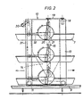
- Fig. 2 einen vertikalen Längsschnitt entsprechend Linie 11-11 in Fig. 1; und
- Fig. 3 eine vergrößerte perspektivische Teildarstellung eines Auslauftrichters mit Scheibe und Trog.
- 1 shows a vertical cross section through a cage battery with the feed wagon.
- Fig. 2 is a vertical longitudinal section along line 11-11 in Fig. 1; and
- Fig. 3 is an enlarged partial perspective view of an outlet funnel with disc and trough.
Gemäß Fig. 1 ist eine Käfigbatterie 1 mit Käfigen 2 vorgesehen, die in Doppelreihen in einer unteren Käfigetage 3, einer mittleren Käfigetage 4 und einer oberen Käfigetage 5 angeordnet sind.1, a cage battery 1 with
Die Käfige 2 sind paarweise mit gemeinsamer Rückseite zusammengebaut, so daß die zugänglichen Vorderseiten der Käfige 2 die Längsseiten der Batterie 1 bilden. Jede Käfigetage 3 bis 5 ist auf gegenüberliegenden Seiten mit einem Eisammelrost 6 und mit einem Etagentrog 7 versehen, die sich in waagerechter Richtung über die ganze Länge der Batterie 1 erstrecken.The
Die gesamte Käfigbatterie 1 ist auf Querschienen 8 abgestützt, an denen auf jeder Längsseite eine längsgerichtete Laufschiene 9 angebracht ist.The entire cage battery 1 is supported on
Auf den beiden Laufschienen 9 ist ein Futterwagen 10 mit vier Rädern 11 verfahrbar. Der Futterwagen 10 besteht im wesentlichen aus zwei schmalen hoch aufragenden Seitenteilen 12 und 13, die oberhalb der Käfigbatterie 1 durch Querstangen 14 zu einer starren Konstruktion miteinander verbunden sind. Dadurch erhält der Futterwagen 10 eine in der Längsrichtung bzw. Fahrtrichtung gesehen etwa umgekehrt u-förmige Gestalt und übergreift die Käfigbatterie von oben an beiden Längsseiten.A
Jedes Seitenteil 12 und 13 bildet einen Futterbehälter 14, der einen bis etwa zur Oberseite der Käfigbatterie 1 aufragenden Höhenförderer 15 aufnimmt. Dieser besteht im wesentlichen aus einem vertikalen Förderrohr 16 mit einer Förderschnecke 17, die von einer an der Oberseite des Futterwagens 10 vorgesehenen Antriebseinrichtung mit einem Fördermotor 18 (Fig. 2) und einer Transmission 19 angetrieben wird.Each
An jedes der beiden Förderrohre 16 sind drei Auslauftrichter 20 angeschlossen, die jeweils in einen der drei Tröge 7 auf der betreffenden Längsseite der Käfigbatterie 1 herabragen und mit einer drehbaren Scheibe 21 versehen sind.To each of the two
Gemäß Fig. 3 ist jeder Auslauftrichter 20 mit seinem oberen Ende an eine Abgabeöffnung 22 des Förderrohrs 16 angeschlossen. Die Förderschnecke 17 gibt durch die Abgabeöffnungen 22 dosierte Futtermengen ab, wobei überschüssiges Futter am oberen Ende des Förderrohrs wieder in den Futterbehälter 14 abgeworfen wird. Der abwärts geneigte Trichterkanal 23 weist einen im wesentlichen rechteckigen Querschnitt auf und ist dabei von einer unteren Trichterwand 24, einer oberen Trichterwand 25 und zwei seitlichen Trichterwänden 26 begrenzt. In der unteren Trichterwand 24 ist eine Wandöffnung 27 ausgebildet, die sich über die ganze Breite und im wesentlichen die gesamte Länge des Trichterkanals 23 erstreckt.3, each
Im Bereich der Wandöffnung 27 wird der Trichterkanal 23 von der Scheibe 21 bzw. ihrer schräg nach oben weisenden Kreisfläche 28 begrenzt. Dabei weist die Scheibe 21 einen die Länge der Wandöffnung 27 etwas übersteigenden Durchmesser auf. Die Scheibe 21 ist mit ihrer durch die Scheibenwelle 29 verlaufenden Drehachse in Längsrichtung zur einen Seite des Auslauftrichters 20 hin versetzt angeordnet, ragt aber auch noch über die andere Seite des Auslauftrichters 20 vor, wie es aus Fig. 3 zu ersehen ist. Jede der insgesamt sechs Scheiben 21 ist mit ihrer Scheibenwelle 29 im betreffenden Seitenteil 12 bzw. 13 drehbar gelagert.In the area of the wall opening 27, the funnel channel 23 is delimited by the
Der Fahrantrieb für die Räder 11 des Futterwagens 10 weist gemäß Fig. 2 einen Fahrmotor 30 und einen umlaufenden Antriebsgurt oder eine Antriebskette 31 auf. Diese treibt die Räder 11 und über Transmissionen 32 auch die Scheiben 21 an.According to FIG. 2, the travel drive for the
Wie in Fig. 2 angedeutet kann die Antriebskette 31 sowohl in der einen wie in der entgegengesetzten Richtung umlaufen, um den Futterwagen 10 in der einen oder in der entgegengesetzten Richtung auf den Laufschienen 9 zu verfahren, wie es jeweils durch einen vollflächigen Pfeil und einen nur mit einer Umrißlinie gezeichneten Pfeil angedeutet ist. Dementsprechend drehen sich auch die Scheiben 21 entweder in der einen oder in der anderen Richtung um ihre Achse, wie es gleichfalls auch in Fig. 3 dargestellt ist. Die mit einem eigenen Antrieb versehene Förderschnecke 17 wird natürlich in beiden Fahrtrichtungen gleichsinnig angetrieben. Durch die Drehung der Scheibe 21 wird deren Kreisfläche im Bereich der Wandöffnung 27 entsprechend dem Pfeil 33 im wesentlichen aufwärts - bei entgegengesetzter Fahrtrichtung abwärts - bewegt. Dadurch wird wirksam vermieden, daß durch den Trichterkanal 23 über die Kreisfläche 28 der Scheibe 21 herabrutschendes Futter sich im Auslauftrichter 20 festsetzt. Somit wird das Futter kontinuierlich am unteren Ende des Auslauftrichters 20 abgegeben. Dementsprechend werden alle sechs Tröge vom Futterwagen 10 über ihre Länge gleichmäßig gefüllt, so daß das Futter gleichmäßig verteilt wird.As indicated in Fig. 2, the
Zusammengefaßt läßt sich die Erfindung wie folgt darstellen: Der Futterwagen ist mit wenigstens einem Höhenförderer und mit einem an diesen angeschlossenen abwärts geneigten Auslauftrichter versehen, dessen Trichterkanal eine Wandöffnung aufweist, die durch eine Kreisfläche einer Scheibe geschlossen gehalten wird, die mit einem Drehantrieb versehen ist. Durch die Drehbewegung der Scheibe wird das Futter an einer Brückenbildung im Auslauftrichter gehindert und dementsprechend in einem kontinuierlichen gleichmäßigen Strom abgegeben.The invention can be summarized as follows: The feed wagon is provided with at least one height conveyor and with a downwardly inclined discharge funnel, the funnel channel of which has a wall opening has, which is kept closed by a circular surface of a disc which is provided with a rotary drive. The rotary movement of the disc prevents the feed from bridging in the discharge funnel and is accordingly released in a continuous, uniform flow.
Claims (5)
Priority Applications (1)
| Application Number | Priority Date | Filing Date | Title |
|---|---|---|---|
| AT86114832T ATE46241T1 (en) | 1985-10-26 | 1986-10-24 | FEED TROLLEY FOR A MULTI-DAY CAGE BATTERY. |
Applications Claiming Priority (2)
| Application Number | Priority Date | Filing Date | Title |
|---|---|---|---|
| DE3538179 | 1985-10-26 | ||
| DE19853538179 DE3538179A1 (en) | 1985-10-26 | 1985-10-26 | FEEDING TROLLEY FOR A MULTI-DAY CAGE BATTERY |
Publications (2)
| Publication Number | Publication Date |
|---|---|
| EP0220699A1 EP0220699A1 (en) | 1987-05-06 |
| EP0220699B1 true EP0220699B1 (en) | 1989-09-13 |
Family
ID=6284569
Family Applications (1)
| Application Number | Title | Priority Date | Filing Date |
|---|---|---|---|
| EP86114832A Expired EP0220699B1 (en) | 1985-10-26 | 1986-10-24 | Feeding carriage for a battery cage of several stories |
Country Status (5)
| Country | Link |
|---|---|
| US (1) | US4844017A (en) |
| EP (1) | EP0220699B1 (en) |
| AT (1) | ATE46241T1 (en) |
| DE (2) | DE3538179A1 (en) |
| GR (1) | GR3000204T3 (en) |
Families Citing this family (12)
| Publication number | Priority date | Publication date | Assignee | Title |
|---|---|---|---|---|
| US5062389A (en) * | 1990-08-21 | 1991-11-05 | Ctb, Inc. | Feed car apparatus |
| US5549075A (en) * | 1994-11-09 | 1996-08-27 | Golden; James B. | Automatic bird feeder |
| US8154412B2 (en) * | 2009-02-13 | 2012-04-10 | Verdiramo Vincent L | Hand wash monitoring system and method |
| US8800752B2 (en) | 2012-05-17 | 2014-08-12 | David W. Sammons | Portable continuous feed delivery system and method of use |
| DE102012104913A1 (en) * | 2012-06-06 | 2013-12-12 | Förster Technik GmbH | Method and device for feeding animals in confined spaces with feed |
| CN103461196B (en) * | 2013-08-22 | 2014-12-24 | 四川宁氏牧业设备有限公司 | Discharging adjustment device for travelling feeding system |
| CN106879489B (en) * | 2017-03-23 | 2023-05-09 | 宜川县鑫丰生态养殖有限责任公司 | Automatic chicken coop that control was fed and is eaten |
| CN106973822B (en) * | 2017-04-27 | 2020-06-09 | 新希望六和股份有限公司 | Chick breeding cage |
| CN109496884B (en) * | 2018-12-29 | 2023-09-26 | 佛山科学技术学院 | Feeding device |
| CN110268994B (en) * | 2019-06-18 | 2021-12-28 | 湖南欣牧达畜牧设备有限公司 | Conveniently get poultry feeding device of egg |
| CN110269000B (en) * | 2019-06-18 | 2022-06-17 | 湖南欣牧达畜牧设备有限公司 | Poultry breeding device convenient for feed feeding and operation method thereof |
| CN111789038B (en) * | 2019-12-21 | 2022-03-29 | 华南理工大学 | Layered dairy cow feeding system and feeding method |
Family Cites Families (7)
| Publication number | Priority date | Publication date | Assignee | Title |
|---|---|---|---|---|
| DE7413448U (en) * | 1974-07-18 | Salmet Gmbh & Co Kg | Feed distributor for a battery of cages | |
| US4056215A (en) * | 1976-04-26 | 1977-11-01 | Elex A.G. | Anti-bridging device |
| US4346802A (en) * | 1977-11-17 | 1982-08-31 | Popper Engineering Ltd. | Combination anti-bridging device and vibrating tray |
| US4195594A (en) * | 1978-01-25 | 1980-04-01 | Diamond International Corporation | Feeding system for animals |
| US4337729A (en) * | 1980-05-13 | 1982-07-06 | Chore-Time Equipment, Inc. | Traveling hopper feed delivery system |
| US4379439A (en) * | 1981-09-14 | 1983-04-12 | Baur Robert P | Animal feeder |
| DE3213688C2 (en) * | 1982-04-14 | 1984-07-26 | Hubert 4591 Cappeln Weßjohann | Feed dispenser for feeding pigs with masses of feed that tend to form bridges |
-
1985
- 1985-10-26 DE DE19853538179 patent/DE3538179A1/en not_active Withdrawn
-
1986
- 1986-10-24 AT AT86114832T patent/ATE46241T1/en not_active IP Right Cessation
- 1986-10-24 EP EP86114832A patent/EP0220699B1/en not_active Expired
- 1986-10-24 DE DE8686114832T patent/DE3665526D1/en not_active Expired
- 1986-10-27 US US06/923,333 patent/US4844017A/en not_active Expired - Lifetime
-
1989
- 1989-11-01 GR GR89400228T patent/GR3000204T3/en unknown
Also Published As
| Publication number | Publication date |
|---|---|
| US4844017A (en) | 1989-07-04 |
| DE3665526D1 (en) | 1989-10-19 |
| ATE46241T1 (en) | 1989-09-15 |
| DE3538179A1 (en) | 1987-04-30 |
| GR3000204T3 (en) | 1990-12-31 |
| EP0220699A1 (en) | 1987-05-06 |
Similar Documents
| Publication | Publication Date | Title |
|---|---|---|
| EP0220699B1 (en) | Feeding carriage for a battery cage of several stories | |
| EP0408837B1 (en) | Device for ballast cleaning machines | |
| DE2143399A1 (en) | Device for drying green fodder | |
| DE2016968A1 (en) | Device for washing stones and the like from disordered, specifically lighter materials, in particular from sugar cane | |
| DE2906672C2 (en) | ||
| DE2647721C2 (en) | ||
| DE3727451C2 (en) | Fermentation arrangement | |
| DE2604752A1 (en) | Tractor towed potato planting machine - has ridge plough and container with conveyor on two adjacent vertical belts with scoops (NL 9.8.77) | |
| DE827323C (en) | Device for emptying containers filled with granular material | |
| DE3248599C2 (en) | ||
| DE1084199B (en) | Belt bunker, especially for wood chips and other loose material | |
| DE967338C (en) | Loading device in which a pick-up is arranged to be pivotable about a vertical axis at the lower end of a high conveyor | |
| DE70046C (en) | A flooring machine for concrete and similar materials | |
| DE3524778C1 (en) | Device for picking up and removing field crops stored in piles | |
| DE1431611A1 (en) | Sponsor | |
| DE817660C (en) | Potato planter | |
| DE6605237U (en) | CONVEYOR DEVICE FOR MANURE AND THE LIKE. | |
| DE1800144C (en) | Mobile machine for clearing, picking up and distributing the ballast | |
| DE2610658B2 (en) | Silo system, especially for clay and clay-like masses | |
| DE572575C (en) | Cleaning device for grain | |
| DE1280270B (en) | Profile-free machine for cleaning the railway bed ballast | |
| DE1442171C (en) | Germination box | |
| DE940183C (en) | Device for the uninterrupted extraction of liquids from solids, especially oils | |
| DE2317036A1 (en) | POTATO SKIN MACHINE WITH SEVERAL LAYING CHAINS | |
| DE2024976A1 (en) | Potato planting machine with guide channel |
Legal Events
| Date | Code | Title | Description |
|---|---|---|---|
| PUAI | Public reference made under article 153(3) epc to a published international application that has entered the european phase |
Free format text: ORIGINAL CODE: 0009012 |
|
| AK | Designated contracting states |
Kind code of ref document: A1 Designated state(s): AT BE DE FR GB GR NL |
|
| 17P | Request for examination filed |
Effective date: 19870923 |
|
| 17Q | First examination report despatched |
Effective date: 19880509 |
|
| GRAA | (expected) grant |
Free format text: ORIGINAL CODE: 0009210 |
|
| AK | Designated contracting states |
Kind code of ref document: B1 Designated state(s): AT BE DE FR GB GR NL |
|
| REF | Corresponds to: |
Ref document number: 46241 Country of ref document: AT Date of ref document: 19890915 Kind code of ref document: T |
|
| REF | Corresponds to: |
Ref document number: 3665526 Country of ref document: DE Date of ref document: 19891019 |
|
| ET | Fr: translation filed | ||
| GBT | Gb: translation of ep patent filed (gb section 77(6)(a)/1977) | ||
| REG | Reference to a national code |
Ref country code: GR Ref legal event code: FG4A Free format text: 3000204 |
|
| PLBE | No opposition filed within time limit |
Free format text: ORIGINAL CODE: 0009261 |
|
| STAA | Information on the status of an ep patent application or granted ep patent |
Free format text: STATUS: NO OPPOSITION FILED WITHIN TIME LIMIT |
|
| 26N | No opposition filed | ||
| PGFP | Annual fee paid to national office [announced via postgrant information from national office to epo] |
Ref country code: GR Payment date: 19931014 Year of fee payment: 8 Ref country code: GB Payment date: 19931014 Year of fee payment: 8 Ref country code: AT Payment date: 19931014 Year of fee payment: 8 |
|
| PGFP | Annual fee paid to national office [announced via postgrant information from national office to epo] |
Ref country code: FR Payment date: 19931015 Year of fee payment: 8 |
|
| PGFP | Annual fee paid to national office [announced via postgrant information from national office to epo] |
Ref country code: BE Payment date: 19931028 Year of fee payment: 8 |
|
| PGFP | Annual fee paid to national office [announced via postgrant information from national office to epo] |
Ref country code: NL Payment date: 19931031 Year of fee payment: 8 |
|
| PGFP | Annual fee paid to national office [announced via postgrant information from national office to epo] |
Ref country code: DE Payment date: 19931217 Year of fee payment: 8 |
|
| PG25 | Lapsed in a contracting state [announced via postgrant information from national office to epo] |
Ref country code: GB Effective date: 19941024 Ref country code: AT Effective date: 19941024 |
|
| PG25 | Lapsed in a contracting state [announced via postgrant information from national office to epo] |
Ref country code: BE Effective date: 19941031 |
|
| BERE | Be: lapsed |
Owner name: FIRMA SALMET G.M.B.H. & CO. K.G. Effective date: 19941031 |
|
| PG25 | Lapsed in a contracting state [announced via postgrant information from national office to epo] |
Ref country code: GR Free format text: THE PATENT HAS BEEN ANNULLED BY A DECISION OF A NATIONAL AUTHORITY Effective date: 19950430 |
|
| PG25 | Lapsed in a contracting state [announced via postgrant information from national office to epo] |
Ref country code: NL Effective date: 19950501 |
|
| NLV4 | Nl: lapsed or anulled due to non-payment of the annual fee | ||
| GBPC | Gb: european patent ceased through non-payment of renewal fee |
Effective date: 19941024 |
|
| PG25 | Lapsed in a contracting state [announced via postgrant information from national office to epo] |
Ref country code: FR Effective date: 19950630 |
|
| REG | Reference to a national code |
Ref country code: GR Ref legal event code: MM2A Free format text: 3000204 |
|
| PG25 | Lapsed in a contracting state [announced via postgrant information from national office to epo] |
Ref country code: DE Effective date: 19950701 |
|
| REG | Reference to a national code |
Ref country code: FR Ref legal event code: ST |