EP0220249B1 - Sicherheitsanordnung für schalter - Google Patents
Sicherheitsanordnung für schalter Download PDFInfo
- Publication number
- EP0220249B1 EP0220249B1 EP86902803A EP86902803A EP0220249B1 EP 0220249 B1 EP0220249 B1 EP 0220249B1 EP 86902803 A EP86902803 A EP 86902803A EP 86902803 A EP86902803 A EP 86902803A EP 0220249 B1 EP0220249 B1 EP 0220249B1
- Authority
- EP
- European Patent Office
- Prior art keywords
- fuse
- barring
- pins
- box
- switch
- Prior art date
- Legal status (The legal status is an assumption and is not a legal conclusion. Google has not performed a legal analysis and makes no representation as to the accuracy of the status listed.)
- Expired
Links
- 230000007935 neutral effect Effects 0.000 claims abstract description 6
- 230000037431 insertion Effects 0.000 claims abstract description 5
- 238000003780 insertion Methods 0.000 claims abstract description 5
- 230000000694 effects Effects 0.000 claims 1
- 238000010276 construction Methods 0.000 description 5
- 238000005192 partition Methods 0.000 description 5
- 230000008878 coupling Effects 0.000 description 1
- 238000010168 coupling process Methods 0.000 description 1
- 238000005859 coupling reaction Methods 0.000 description 1
- 230000000284 resting effect Effects 0.000 description 1
- 210000003813 thumb Anatomy 0.000 description 1
Images
Classifications
-
- H—ELECTRICITY
- H01—ELECTRIC ELEMENTS
- H01H—ELECTRIC SWITCHES; RELAYS; SELECTORS; EMERGENCY PROTECTIVE DEVICES
- H01H9/00—Details of switching devices, not covered by groups H01H1/00 - H01H7/00
- H01H9/10—Adaptation for built-in fuses
- H01H9/104—Adaptation for built-in fuses with interlocking mechanism between switch and fuse
-
- H—ELECTRICITY
- H01—ELECTRIC ELEMENTS
- H01H—ELECTRIC SWITCHES; RELAYS; SELECTORS; EMERGENCY PROTECTIVE DEVICES
- H01H85/00—Protective devices in which the current flows through a part of fusible material and this current is interrupted by displacement of the fusible material when this current becomes excessive
- H01H85/02—Details
- H01H85/0208—Tools for inserting and removing fuses
Definitions
- the present invention relates to a safety device for use in connection with power switches of a type known per se and comprising a substantially box-shaped breaker box with a number of one-sidedly located contact pieces which are in pairs intended to secure a fuse formed as a fuse body and two opposite terminal legs extending there from.
- switches of the above type are often only shielded by means of mounted plastic partitions between the fuses and their holders (the contact pieces), which has resulted in a construction of switch boards, where each switch is mounted below separate doors or covers, which can only be opened when the switch in question is disconnected. This will obviously increase the price of switchboards, the daily operation of which is difficult and time-consuming.
- SE-A-219225 and DE-B-1069270 relate to a cover with a manually operated closing handle resiliently movable for cooperation with carrier pins engaging the fuse vanes.
- Switches with built-in safety devices are known preventing unauthorised access to live parts when the fuse has been mounted and the switch connected; however, no safety device is known, which, if desired, can be mounted as a separate unit on existing power switches of the above type and which can simultaneously offer the necessary safety.
- a safety device is hereby obtained which can easily be mounted as a separate unit on existing power switches and will consequently imply protection against the situation, where a impatient electrician is injured during an attempt of removing or inserting a fuse by means of an available unsuitable tool while the switch is connected.
- the safety device according to the invention prevents everybody from coming into contact at all with live parts in a connected switch via the terminal legs of the fuse by means of an inappropriate manipulation with the fuse, e.g. by an oblique insertion of the fuse into the fuse box. The space will prevent this.
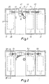
- Fig. 1 of the drawing illustrates a position indicator 15 on the axle of the handle as well as markings for the in- and out-position, "I" and "O", respectively, of the switch.
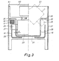
- a respective box-shaped shielded fuse box in Figs. 1 and 2 designated 17, 19, and 21, is positioned around each pair of contact pieces, only indicated in Fig. 3 of the drawing at positions 16, there being a fuse box for each of the three phases normally available.
- a DIN-standardized knife fuse consisting of a fuse body 23 and a terminal leg 25 in each end is inserted into each box as indicated by dotted line.
- Each fuse box comprises in particular an outer box 27 open at the top and the bottom; said outer box carries in the inner of the central third part a chamber for the fuse body 23, said chamber being substantially U-shaped in section.
- the chamber is formed by two inner end walls 29 and a bottom wall 31. Each inner wall 29 is at the top connected to an outer end wall through a horizontal partition 33.
- the mutual distance between the inner end walls 29 is only somewhat greater than the length of the fuse body 23, so that only little clearance d is left between the end surfaces of the fuse body 23 and the inner end walls 29 of the fuse box.
- end walls 29 and the horizontal partitions 33 furthermore comprise a slot 35 each allowing insertion of the terminal legs of the fuse for engaging a contact piece 16 each.
- the fuse boxes 17, 19, and 21 may be fastened to the breaker box 11 by means of screws or suitable snap-action device; this is not illustrated in the drawing.
- Each fuse box comprises a barring pin 41, 43, and 45, respectively, situated in the same horizontal and vertical plane and resting in suitable recesses in the side walls of the fuse boxes at a level between a horizontal partition 33 and the upper end of a contact piece 16.
- the barring pins can be moved longitudinally between the two outermost positions by means of a suitable manoeuvring means, e.g. an appropriately formed cam disc 47 placed on the axle 13 of the handle.
- a suitable manoeuvring means e.g. an appropriately formed cam disc 47 placed on the axle 13 of the handle.
- the cam disc 47 has manoeuvred all barring pins to the barring position as illustrated in Fig. 2. This takes place under the surmounting of small spring forces from the springs 51, 53, and 55 ensuring the return of the pins to the neutral position when the switch is disconnected. It should be noted that as far as the two adjacent fuse boxes - which in the drawing are positioned to the right of the handle axis 13 - are concerned, the outer barring pin 45 is indirectly influenced through the inner barring pin 43.
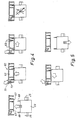
- Each fuse box is furthermore covered by a specially formed cover according to the invention as illustrated in Figs. 3, 4, and 5.
- the cover provided with the general reference number 60, abuts the upper edge of the outer box walls 27 with an edge flange 61, cf. Fig. 3.
- a central section of the cover is opened in the side walls to form a handle portion 63 and is on the underside constructed with open cells separated by partitions 65.
- the cover is provided with carrier pins 67 for engaging eye-shaped fuse vanes 69, which by way of standard are provided at the ends of the fuse body 23 of each fuse.
- a closing handle 71 is provided in one end wall of the cover opposite a carrier pin 67 through suitable recesses in the end wall and on the top side; the closing handle may be bent outwards, away from the center of the handle or the cover, the cover being made of a material sufficiently elastic to make such a deflection possible.
- the closing handle 71 is furthermore provided with a downwardly projecting nose 73 for cooperation with a fuse vane 69 as illustrated in Figs. 4 and 5, which are a longitudinal sectional view of the cover 60 and a sectional view of the fuse.
- the construction of the cover further allows the removal of a hot fuse without it being touched, as the closing handle 71 after removal from the fuse box in question is easily bent outwards by a push with a thumb, whereafter the fuse is capable of sliding off freely, if the handle is tilted at a suitable angle.
Landscapes
- Switch Cases, Indication, And Locking (AREA)
- Fuses (AREA)
- Push-Button Switches (AREA)
- Driving Mechanisms And Operating Circuits Of Arc-Extinguishing High-Tension Switches (AREA)
- Automotive Seat Belt Assembly (AREA)
- Keying Circuit Devices (AREA)
Claims (3)
- Sicherheitsvorrichtung für einen beliebigen Leistungsschalter mit einem im wesentlichen kastenförmigen Unterbrechergehäuse (11) mit mehreren vorspringenden Kontaktstücken (16), die paarweise angeordnet sind, wobei jedes Paar die Aufgabe hat, eine Sicherung mit einem Sicherungskörper (23) und zwei gegenüberstehenden Anschlußschenkeln (25), die sich von ihm erstrecken, zu haltern, dadurch gekennzeichnet, daß die Anordnung aufweist: mehrere Sicherungskästen (17, 19, 21) zum individuellen Befestigen auf dem Unterbrecherkasten (11) und zum Abschirmen eines Paares von Kontaktstücken (16) mit einer angeschlossenen Sicherung (23, 25), jeweils einen Verriegelungsstift (41, 43, 45) für jeden Sicherungskasten, die in dem Unterbrecherkasten (11) gegen die Kraft einer Feder (51, 53, 55) zwischen einer neutralen Position und einer Verriegelungsposition in Längsrichtung verschiebbar angeordnet sind, und eine Manövriereinheit (47) zum kollektiven Betätigen der Verriegelungsstifte entweder direkt oder indirekt, so daß die Verriegelungsstifte in der Ein-Position ("I") des Schalters in die Verriegelungsposition und in der Aus-Position ("O") des Schalters in die neutrale Position verschoben werden, und wobei jeder Sicherungskasten auf seiner Innenseite mit inneren Wänden (29, 31, 33) auf solche Weise versehen ist, daß die Sicherung (23, 25) zu ihnen einen so kleinen Abstand (d) wie möglich hat, daß er eine schräge Befestigung der Sicherung unmöglich macht, und wobei die Verriegelungsstifte (41, 43, 45) in der Verriegelungsposition das Entfernen bzw. das Einsetzen einer Sicherung aus ihren bzw. in ihre entsprechenden Kontaktstücke(n) (16) unmöglich machen.
- Sicherheitsanordnung nach Anspruch 1, dadurch gekennzeichnet, daß sie ferner eine Abdeckung (60) für jeden Sicherungskasten aufweist, wobei die Abdeckung ein Handhabungsteil (63) und einen starren und manuell betätigten Verschlußgriff (71) aufweist, der elastisch aus einer Ruhelage beweglich ist und mit einem Ende für das Einwirken auf eine der Sicherungsplatten (69) auf dem Sicherungskörper (23) vorgesehen ist und der Trägerstifte (67) auf der Unterseite aufweist, um in die Sicherungsplatten einzugreifen und die Sicherung zu tragen, wobei der Verschlußgriff (71) in einer Ruheposition das unbeabsichtigte Abgleiten einer Sicherungsplatte aus einem Trägerstift verhindert.
- Sicherheitsvorrichtung nach Anspruch 2, dadurch gekennzeichnet, daß der Verschlußgriff (71) so ausgebildet ist, daß er selbsttätig verriegelt, wenn die Abdeckung (60) befestigt wurde.
Priority Applications (1)
| Application Number | Priority Date | Filing Date | Title |
|---|---|---|---|
| AT86902803T ATE65147T1 (de) | 1985-04-17 | 1986-04-16 | Sicherheitsanordnung fuer schalter. |
Applications Claiming Priority (2)
| Application Number | Priority Date | Filing Date | Title |
|---|---|---|---|
| DK1743/85 | 1985-04-17 | ||
| DK174385A DK160115C (da) | 1985-04-17 | 1985-04-17 | Sikkerhedsindretning til stroemafbrydere |
Publications (2)
| Publication Number | Publication Date |
|---|---|
| EP0220249A1 EP0220249A1 (de) | 1987-05-06 |
| EP0220249B1 true EP0220249B1 (de) | 1991-07-10 |
Family
ID=8107706
Family Applications (1)
| Application Number | Title | Priority Date | Filing Date |
|---|---|---|---|
| EP86902803A Expired EP0220249B1 (de) | 1985-04-17 | 1986-04-16 | Sicherheitsanordnung für schalter |
Country Status (5)
| Country | Link |
|---|---|
| EP (1) | EP0220249B1 (de) |
| AU (1) | AU588595B2 (de) |
| DK (1) | DK160115C (de) |
| FI (1) | FI86012C (de) |
| WO (1) | WO1986006221A1 (de) |
Cited By (1)
| Publication number | Priority date | Publication date | Assignee | Title |
|---|---|---|---|---|
| DE4204238C2 (de) * | 1992-02-13 | 2000-06-21 | Moeller Gmbh | Einschub mit einer schaltbaren NH-Sicherungsleiste für Einschubverteiler |
Families Citing this family (3)
| Publication number | Priority date | Publication date | Assignee | Title |
|---|---|---|---|---|
| DE9308495U1 (de) * | 1993-06-07 | 1994-10-20 | Weber AG, Emmenbrücke | Ein- oder mehrpolige NH-Sicherung |
| US6833519B1 (en) | 1999-07-22 | 2004-12-21 | Klaus Bruchmann | Switching system with a combined switching and blocking device |
| DE29913698U1 (de) * | 1999-08-05 | 1999-11-04 | Bruchmann, Klaus, 96450 Coburg | Mehrpolige Schaltersicherungsanordnung für Sammelschienensysteme |
Family Cites Families (6)
| Publication number | Priority date | Publication date | Assignee | Title |
|---|---|---|---|---|
| DE361514C (de) * | 1922-10-16 | Voigt & Haeffner Akt Ges | Verriegelungsanordnung zwischen mehr als zwei Schalterantrieben | |
| US2342852A (en) * | 1942-11-19 | 1944-02-29 | Bulldog Electric Prod Co | Switch |
| DE1069270B (de) * | 1956-08-11 | 1959-11-19 | Siemens Ag | Sicherungsgriffzange zum einsetzen von nh-sicherungen |
| GB859084A (en) * | 1956-09-07 | 1961-01-18 | English Electric Co Ltd | Improvements in and relating to electric fusegear |
| DE1150434B (de) * | 1958-02-10 | 1963-06-20 | Bassani Spa | Verriegelnder elektrischer Kippschalter |
| DE2618360C3 (de) * | 1976-04-27 | 1983-11-03 | Lindner Gmbh, Fabrik Elektrischer Lampen Und Apparate, 8600 Bamberg | Sicherungssockel mit eingebautem Schalter |
-
1985
- 1985-04-17 DK DK174385A patent/DK160115C/da not_active IP Right Cessation
-
1986
- 1986-04-16 EP EP86902803A patent/EP0220249B1/de not_active Expired
- 1986-04-16 WO PCT/DK1986/000041 patent/WO1986006221A1/en not_active Ceased
- 1986-04-16 AU AU58113/86A patent/AU588595B2/en not_active Ceased
- 1986-12-11 FI FI865055A patent/FI86012C/fi not_active IP Right Cessation
Cited By (1)
| Publication number | Priority date | Publication date | Assignee | Title |
|---|---|---|---|---|
| DE4204238C2 (de) * | 1992-02-13 | 2000-06-21 | Moeller Gmbh | Einschub mit einer schaltbaren NH-Sicherungsleiste für Einschubverteiler |
Also Published As
| Publication number | Publication date |
|---|---|
| DK160115C (da) | 1991-07-01 |
| EP0220249A1 (de) | 1987-05-06 |
| AU5811386A (en) | 1986-11-05 |
| WO1986006221A1 (en) | 1986-10-23 |
| DK174385A (da) | 1986-10-18 |
| FI865055A0 (fi) | 1986-12-11 |
| DK160115B (da) | 1991-01-28 |
| AU588595B2 (en) | 1989-09-21 |
| FI865055A7 (fi) | 1986-12-11 |
| FI86012B (fi) | 1992-03-13 |
| DK174385D0 (da) | 1985-04-17 |
| FI86012C (fi) | 1992-06-25 |
Similar Documents
| Publication | Publication Date | Title |
|---|---|---|
| CN100474481C (zh) | 保险丝装置 | |
| US3171908A (en) | Handle operating mechanism for enclosed electric devices | |
| EP0204479A2 (de) | Verriegelungseinrichtung eines Steuerhebels für Lastschalter | |
| AP593A (en) | Enclosure for a circuit breaker. | |
| US4827089A (en) | Molded case circuit breaker interlock arrangement | |
| CZ2002390A3 (cs) | Vícepólové bezpečnostní spínací zařízení | |
| US4496916A (en) | Switch fuse unit | |
| EP0717425B1 (de) | Differenzielles Schutzmodul mit multipolarem Schaltblock mit Sicherheitskupplung zur Ankupplung an den multipolaren Schaltblock | |
| US5027091A (en) | Molded case circuit interrupter rating plug keying and interlock arrangement | |
| US5936214A (en) | Apparatus for restricting operation of push buttons on electric switching apparatus | |
| KR880005640A (ko) | 상호 교환가능한 전자개폐 스위치장치 | |
| US5060107A (en) | Molded case circuit breaker operating handle guard | |
| US4034169A (en) | Electric switchgear device with interlocking handle means | |
| EP0220249B1 (de) | Sicherheitsanordnung für schalter | |
| US6531948B1 (en) | Fuse handler | |
| US2263760A (en) | Enclosed circuit breaker | |
| US5486666A (en) | Protective cover for electrical terminals and method of using same | |
| DK157467B (da) | Lille kontaktor med en aftagelig underenhed af hjaelpeafbrydere | |
| US3076876A (en) | Means for locking circuit breaker operating handles | |
| US3295025A (en) | Movable barrier serving as shutter means and enclosure door in switchgear housing | |
| US3141934A (en) | Enclosed electric switch with rotary type operating handle and interlocking mechanism | |
| EP1112585B1 (de) | Niederspannungsschaltgerät mit bimetallauslöser | |
| US4547634A (en) | Electrical appliance interlock switch with improved buss | |
| GB1270188A (en) | Interlocking fuse and switch assembly | |
| US3171007A (en) | Circuit breaker actuator box |
Legal Events
| Date | Code | Title | Description |
|---|---|---|---|
| PUAI | Public reference made under article 153(3) epc to a published international application that has entered the european phase |
Free format text: ORIGINAL CODE: 0009012 |
|
| AK | Designated contracting states |
Kind code of ref document: A1 Designated state(s): AT BE CH DE FR GB IT LI LU NL SE |
|
| 17P | Request for examination filed |
Effective date: 19870403 |
|
| 17Q | First examination report despatched |
Effective date: 19890602 |
|
| GRAA | (expected) grant |
Free format text: ORIGINAL CODE: 0009210 |
|
| AK | Designated contracting states |
Kind code of ref document: B1 Designated state(s): AT BE CH DE FR GB IT LI LU NL SE |
|
| PG25 | Lapsed in a contracting state [announced via postgrant information from national office to epo] |
Ref country code: LI Effective date: 19910710 Ref country code: CH Effective date: 19910710 Ref country code: BE Effective date: 19910710 Ref country code: AT Effective date: 19910710 |
|
| REF | Corresponds to: |
Ref document number: 65147 Country of ref document: AT Date of ref document: 19910715 Kind code of ref document: T |
|
| REF | Corresponds to: |
Ref document number: 3680175 Country of ref document: DE Date of ref document: 19910814 |
|
| ITF | It: translation for a ep patent filed | ||
| REG | Reference to a national code |
Ref country code: CH Ref legal event code: PL |
|
| ET | Fr: translation filed | ||
| PG25 | Lapsed in a contracting state [announced via postgrant information from national office to epo] |
Ref country code: LU Free format text: LAPSE BECAUSE OF NON-PAYMENT OF DUE FEES Effective date: 19920430 |
|
| PLBE | No opposition filed within time limit |
Free format text: ORIGINAL CODE: 0009261 |
|
| STAA | Information on the status of an ep patent application or granted ep patent |
Free format text: STATUS: NO OPPOSITION FILED WITHIN TIME LIMIT |
|
| 26N | No opposition filed | ||
| REG | Reference to a national code |
Ref country code: GB Ref legal event code: 732 |
|
| ITPR | It: changes in ownership of a european patent |
Owner name: CESSIONE;HOLEC LK A/S |
|
| REG | Reference to a national code |
Ref country code: FR Ref legal event code: TP |
|
| NLS | Nl: assignments of ep-patents |
Owner name: HOLEC SYSTEMEN EN COMPONENTEN B.V. TE HENGELO (O.) |
|
| ITPR | It: changes in ownership of a european patent |
Owner name: CESSIONE;HOLEC SYSTEMEN & COMPONENTEN B.V. |
|
| EAL | Se: european patent in force in sweden |
Ref document number: 86902803.5 |
|
| NLS | Nl: assignments of ep-patents |
Owner name: HOLEC HOLLAND N.V. |
|
| REG | Reference to a national code |
Ref country code: GB Ref legal event code: 732E |
|
| REG | Reference to a national code |
Ref country code: FR Ref legal event code: TP |
|
| PG25 | Lapsed in a contracting state [announced via postgrant information from national office to epo] |
Ref country code: FR Free format text: LAPSE BECAUSE OF NON-PAYMENT OF DUE FEES Effective date: 20011231 |
|
| REG | Reference to a national code |
Ref country code: GB Ref legal event code: IF02 |
|
| REG | Reference to a national code |
Ref country code: FR Ref legal event code: ST |
|
| PGFP | Annual fee paid to national office [announced via postgrant information from national office to epo] |
Ref country code: SE Payment date: 20020327 Year of fee payment: 17 |
|
| PGFP | Annual fee paid to national office [announced via postgrant information from national office to epo] |
Ref country code: NL Payment date: 20020328 Year of fee payment: 17 |
|
| PGFP | Annual fee paid to national office [announced via postgrant information from national office to epo] |
Ref country code: GB Payment date: 20020402 Year of fee payment: 17 |
|
| REG | Reference to a national code |
Ref country code: FR Ref legal event code: D3 |
|
| PGFP | Annual fee paid to national office [announced via postgrant information from national office to epo] |
Ref country code: FR Payment date: 20020416 Year of fee payment: 17 |
|
| PGFP | Annual fee paid to national office [announced via postgrant information from national office to epo] |
Ref country code: DE Payment date: 20020418 Year of fee payment: 17 |
|
| PG25 | Lapsed in a contracting state [announced via postgrant information from national office to epo] |
Ref country code: GB Free format text: LAPSE BECAUSE OF NON-PAYMENT OF DUE FEES Effective date: 20030416 |
|
| PG25 | Lapsed in a contracting state [announced via postgrant information from national office to epo] |
Ref country code: SE Free format text: LAPSE BECAUSE OF NON-PAYMENT OF DUE FEES Effective date: 20030417 |
|
| PG25 | Lapsed in a contracting state [announced via postgrant information from national office to epo] |
Ref country code: NL Free format text: LAPSE BECAUSE OF NON-PAYMENT OF DUE FEES Effective date: 20031101 Ref country code: DE Free format text: LAPSE BECAUSE OF NON-PAYMENT OF DUE FEES Effective date: 20031101 |
|
| NLV4 | Nl: lapsed or anulled due to non-payment of the annual fee |
Effective date: 20031101 |
|
| EUG | Se: european patent has lapsed | ||
| GBPC | Gb: european patent ceased through non-payment of renewal fee |
Effective date: 20030416 |
|
| REG | Reference to a national code |
Ref country code: FR Ref legal event code: ST |
|
| PG25 | Lapsed in a contracting state [announced via postgrant information from national office to epo] |
Ref country code: IT Free format text: LAPSE BECAUSE OF NON-PAYMENT OF DUE FEES;WARNING: LAPSES OF ITALIAN PATENTS WITH EFFECTIVE DATE BEFORE 2007 MAY HAVE OCCURRED AT ANY TIME BEFORE 2007. THE CORRECT EFFECTIVE DATE MAY BE DIFFERENT FROM THE ONE RECORDED. Effective date: 20050416 |