EP0220123A1 - Dispositif de transfert d'un fluide cryogenique - Google Patents
Dispositif de transfert d'un fluide cryogenique Download PDFInfo
- Publication number
- EP0220123A1 EP0220123A1 EP86402301A EP86402301A EP0220123A1 EP 0220123 A1 EP0220123 A1 EP 0220123A1 EP 86402301 A EP86402301 A EP 86402301A EP 86402301 A EP86402301 A EP 86402301A EP 0220123 A1 EP0220123 A1 EP 0220123A1
- Authority
- EP
- European Patent Office
- Prior art keywords
- lever
- locking member
- separation member
- end piece
- end pieces
- Prior art date
- Legal status (The legal status is an assumption and is not a legal conclusion. Google has not performed a legal analysis and makes no representation as to the accuracy of the status listed.)
- Granted
Links
Images

Classifications
-
- F—MECHANICAL ENGINEERING; LIGHTING; HEATING; WEAPONS; BLASTING
- F17—STORING OR DISTRIBUTING GASES OR LIQUIDS
- F17C—VESSELS FOR CONTAINING OR STORING COMPRESSED, LIQUEFIED OR SOLIDIFIED GASES; FIXED-CAPACITY GAS-HOLDERS; FILLING VESSELS WITH, OR DISCHARGING FROM VESSELS, COMPRESSED, LIQUEFIED, OR SOLIDIFIED GASES
- F17C13/00—Details of vessels or of the filling or discharging of vessels
- F17C13/005—Details of vessels or of the filling or discharging of vessels for medium-size and small storage vessels not under pressure
-
- F—MECHANICAL ENGINEERING; LIGHTING; HEATING; WEAPONS; BLASTING
- F16—ENGINEERING ELEMENTS AND UNITS; GENERAL MEASURES FOR PRODUCING AND MAINTAINING EFFECTIVE FUNCTIONING OF MACHINES OR INSTALLATIONS; THERMAL INSULATION IN GENERAL
- F16L—PIPES; JOINTS OR FITTINGS FOR PIPES; SUPPORTS FOR PIPES, CABLES OR PROTECTIVE TUBING; MEANS FOR THERMAL INSULATION IN GENERAL
- F16L37/00—Couplings of the quick-acting type
- F16L37/08—Couplings of the quick-acting type in which the connection between abutting or axially overlapping ends is maintained by locking members
- F16L37/084—Couplings of the quick-acting type in which the connection between abutting or axially overlapping ends is maintained by locking members combined with automatic locking
- F16L37/096—Couplings of the quick-acting type in which the connection between abutting or axially overlapping ends is maintained by locking members combined with automatic locking by means of hooks hinged about an axis
-
- F—MECHANICAL ENGINEERING; LIGHTING; HEATING; WEAPONS; BLASTING
- F17—STORING OR DISTRIBUTING GASES OR LIQUIDS
- F17C—VESSELS FOR CONTAINING OR STORING COMPRESSED, LIQUEFIED OR SOLIDIFIED GASES; FIXED-CAPACITY GAS-HOLDERS; FILLING VESSELS WITH, OR DISCHARGING FROM VESSELS, COMPRESSED, LIQUEFIED, OR SOLIDIFIED GASES
- F17C2205/00—Vessel construction, in particular mounting arrangements, attachments or identifications means
- F17C2205/03—Fluid connections, filters, valves, closure means or other attachments
- F17C2205/0302—Fittings, valves, filters, or components in connection with the gas storage device
- F17C2205/0323—Valves
-
- F—MECHANICAL ENGINEERING; LIGHTING; HEATING; WEAPONS; BLASTING
- F17—STORING OR DISTRIBUTING GASES OR LIQUIDS
- F17C—VESSELS FOR CONTAINING OR STORING COMPRESSED, LIQUEFIED OR SOLIDIFIED GASES; FIXED-CAPACITY GAS-HOLDERS; FILLING VESSELS WITH, OR DISCHARGING FROM VESSELS, COMPRESSED, LIQUEFIED, OR SOLIDIFIED GASES
- F17C2223/00—Handled fluid before transfer, i.e. state of fluid when stored in the vessel or before transfer from the vessel
- F17C2223/01—Handled fluid before transfer, i.e. state of fluid when stored in the vessel or before transfer from the vessel characterised by the phase
- F17C2223/0146—Two-phase
- F17C2223/0153—Liquefied gas, e.g. LPG, GPL
- F17C2223/0161—Liquefied gas, e.g. LPG, GPL cryogenic, e.g. LNG, GNL, PLNG
-
- F—MECHANICAL ENGINEERING; LIGHTING; HEATING; WEAPONS; BLASTING
- F17—STORING OR DISTRIBUTING GASES OR LIQUIDS
- F17C—VESSELS FOR CONTAINING OR STORING COMPRESSED, LIQUEFIED OR SOLIDIFIED GASES; FIXED-CAPACITY GAS-HOLDERS; FILLING VESSELS WITH, OR DISCHARGING FROM VESSELS, COMPRESSED, LIQUEFIED, OR SOLIDIFIED GASES
- F17C2265/00—Effects achieved by gas storage or gas handling
- F17C2265/01—Purifying the fluid
- F17C2265/015—Purifying the fluid by separating
Definitions
- the present invention relates to a device for transferring a cryogenic fluid, of the type comprising two nozzles each forming part of a container and cooperating by simple insertion. It applies in particular to the transfer of liquid oxygen from a storage container to a portable container of a home oxygen therapy system.
- a storage container for example 20 to 40 liters of liquid oxygen
- a portable container for example 0.6 to 1.3 liters of liquid oxygen
- Both containers are fitted with filling tips.
- the portable container is filled from the storage container by coupling the male end with the female end and venting the portable container.
- Each nozzle has a valve head provided with a return spring in the closed position. The opening of these valves is obtained either by means of lugs provided on the male end piece and which come to lock on the female end piece (bayonet fittings), or by simple direct pushing of the end pieces one against the 'other during the entire filling time.
- the filling process with bayonet fitting has the advantage of requiring only a small locking force, but has two drawbacks: - positioning vis-à-vis the male and female ends is delicate; - if the coupling is blocked by icing of the parts, the user must wait for them to warm up (5 to 15 minutes) before being able to disconnect them, or take the risk of damaging the tips by forcing.
- the object of the invention is to provide a transfer device by simple insertion of the end pieces into one another which makes it possible both to avoid maintaining the thrust during the transfer and to ensure in all cases a reliable and easy separation of the two tips when the transfer is complete.
- the invention relates to a transfer device of the aforementioned type, characterized in that it comprises a member for separating the two end pieces combined with a member for locking the coupling of the two end pieces so that when the the locking member is in the active position, the separation member is retracted, and vice versa, and a common mechanism for actuating the separation member and the locking member.
- the actuation mechanism comprises a lever which carries the locking member on one side of its articulation axis, the separating member being articulated on the part of the same lever located on the on the other side of this axis.
- the lever is resiliently returned to the active position of the locking member, the latter having a cam surface adapted to cooperate with the end of the associated end piece during the coupling of the two end pieces.
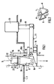
- FIG. 1 Partly shown in Figure 1 the upper part of a liquid oxygen storage container with a capacity of 20 to 40 liters, as well as the connection nozzle 1 of a portable liquid oxygen container having a 0.6 to 1.3 liter capacity, all of which is part of a home oxygen therapy system.
- the storage container essentially comprises an outlet tube 2 of vertical axis XX which passes through an opening 2A formed in the upper wall 3 of the container housing.
- This tubing 2 ends, above the wall 3, by a cylindrical male endpiece 4 comprising a valve head 5 in projection, returned to its closed exit position by a spring (not shown).
- this yoke On the end piece 4 is freely threaded a separation yoke 6. As can be seen in FIG. 2, this yoke has an upper plate 7 pierced with a circular hole 8 of diameter slightly larger than that of the end piece 4 and crossed by it, and two side wings 9 directed downwards. The lower ends of the two wings 9 are articulated respectively on the two branches of a fork 10 formed at one end of an actuating lever 11 and embracing the pipe 2.
- a plate 12 which carries an axis 13 of lever articulation 11.
- a compression spring 14 is interposed between the plate 12 and the lever 11, and on the upper face of the latter is fixed a locking hook 15 which projects above the wall 13, through a slot 15A in this wall, and ends above the plate 7 by a spout 16, which has at its free end an upper cam surface 17 directed obliquely.
- the hook 15 is provided with an adjustable stop 18; when the end pieces 1 and 4 are not engaged, this stop keeps the lever 11 in a roughly horizontal position and the hook 15 in a roughly vertical position, with the underside of the spout 16 about horizontal.
- a rod 19 On the end of the lever 11 opposite the yoke 6 is articulated a rod 19 which carries a push button 20 guided through an opening 20A in the wall 3.
- the end piece 1 is a cylindrical female end piece having a blind bore 21 conjugated with the end piece 4 and the bottom of which is fitted with a valve head 22 biased by a spring (not shown) towards its closed exit position. Furthermore, a circular groove 23 is machined on the outer surface of the end piece 1, near its lower end, and has a lower face 24 perpendicular to the axis of this end piece.
- the end piece 1 is brought above the end piece 4, and it is lowered along the axis XX, with any angular orientation.
- the bore 21 fits onto the end piece 4; its end edge comes into contact with the cam surface 17 of the hook 15 and pushes the latter against the spring 14, then the spout 16 comes snap, under the action of this spring, into the groove 23.
- the two valve heads 5 and 22 are then pushed in and open, which allows the transfer of liquid oxygen, and their springs exert a force which tends to separate the two end pieces.
- the assembly is therefore firmly locked by the hook 15, and the user can let go of the portable container without the risk of liquid oxygen transfer being interrupted. In this position, shown in FIG. 1, the lower end face of the end piece 1 is located a short distance above the plate 7 of the yoke 6.
Abstract
Description
- La présente invention est relative à un dispositif de transfert d'un fluide cryogénique, du type comprenant deux embouts faisant partie chacun d'un récipient et coopérant par simple enfoncement. Elle s'applique en particulier au transfert d'oxygène liquide d'un récipient de stockage à un récipient portable d'un système d'oxygénothérapie à domicile.
- De nombreux systèmes ont été développés pour traiter les insuffisants respiratoires à domicile. Ils comportent un récipient de stockage (par exemple 20 à 40 litres d'oxygène liquide), d'une autonomie d'une à deux semaines, et un récipient portable (par exemple 0,6 à 1,3 litre d'oxygène liquide), d'une autonomie de plusieurs heures. Les deux récipients sont équipés d'embouts de remplissage. Le récipient portable est rempli à partir du récipient de stockage par accouplement de l'embout mâle avec l'embout femelle et mise à l'air du récipient portable. Chaque embout comporte une tête de clapet pourvue d'un ressort de rappel en position de fermeture. L'ouverture de ces clapets est obtenue soit par l'intermédiaire d'ergots prévus sur l'embout mâle et qui viennent se verrouiller sur l'embout femelle (raccords à baïonnette), soit par simple poussée directe des embouts l'un contre l'autre durant tout le temps de remplissage.
- Le procédé de remplissage avec raccord à baïonnette présente l'avantage de ne nécessiter qu'un faible effort de verrouillage, mais comporte deux inconvénients :
- le positionnement en vis-à-vis des embouts mâle et femelle est délicat;
- en cas de blocage de l'accouplement par givrage des pièces,
l'utilisateur doit attendre leur réchauffement (5 à 15 minutes) pour pouvoir les déconnecter, ou prendre le risque de détériorer les embouts en forçant. - Le procédé de remplissage par simple enfoncement de l'embout mâle dans l'embout femelle est plus facile à utiliser ; cependant, il nécessite un effort plus important à exercer et ce pendant toute la durée du remplissage, du fait de l'absence de verrouillage. Par ailleurs se pose également le problème du blocage des raccords par givrage des pièces.
- L'invention a pour but de fournir un dispositif de transfert par simple enfoncement des embouts l'un dans l'autre qui permette à la fois d'éviter le maintien de la poussée pendant le transfert et d'assurer dans tous les cas une séparation fiable et facile des deux embouts lorsque le transfert est terminé.
- A cet effet, l'invention a pour objet un dispositif de transfert du type précité, caractérisé en ce qu'il comprend un organe de séparation des deux embouts combiné à un organe de verrouillage de l'accouplement des deux embouts de façon que lorsque l'organe de verrouillage se trouve en position active, l'organe de séparation soit escamoté, et inversement, et un mécanisme commun d'actionnement de l'organe de séparation et de l'organe de verrouillage.
- Dans un mode de réalisation particulièrement simple, le mécanisme d'actionnement comprend un levier qui porte l'organe de verrouillage d'un côté de son axe d'articulation, l'organe de séparation étant articulé sur la partie du même levier située de l'autre côté de cet axe.
- De préférence, le levier est rappelé élastiquement vers la position active de l'organe de verrouillage, ce dernier présentant une surface de came adaptée pour coopérer avec l'extrémité de l'embout associé pendant l'accouplement des deux embouts.
- Un exemple de réalisation de l'invention va maintenant être décrit en regard des dessins annexés, sur lesquels :
- - la figure 1 est une vue schématique en élévation latérale d'un dispositif de transfert conforme à l'invention, en position verrouillée;
- - la figure 2 est une vue en perspective d'une partie de ce dispositif ; et
- - la figure 3 est une vue analogue à la figure 1 illustrant la séparation des deux embouts.
- On a représenté partiellement à la figure 1 la partie supérieure d'un récipient de stockage d'oxygène liquide d'une capacité de 20 à 40 litres, ainsi que l'embout de raccordement 1 d'un récipient d'oxygène liquide portable ayant une capacité de 0,6 à 1,3 litre, l'ensemble faisant partie d'un système d'oxygénothérapie à domicile.
- Pour ce qui concerne la présente invention, le récipient de stockage comprend essentiellement une tubulure de sortie 2 d'axe vertical X-X qui traverse une ouverture 2A ménagée dans la paroi supérieure 3 du carter du récipient. Cette tubulure 2 se termine, au-dessus de la paroi 3, par un embout mâle cylindrique 4 comportant une tête de clapet 5 en saillie, rappelée vers sa position sortie de fermeture par un ressort (non représenté).
- Sur l'embout 4 est enfilée librement une chape de séparation 6. Comme on le voit bien à la figure 2, cette chape comporte une plaque supérieure 7 percée d'un trou circulaire 8 de diamètre légèrement supérieur à celui de l'embout 4 et traversé par celui-ci, et deux ailes latérales 9 dirigées vers le bas. Les extrémités inférieures des deux ailes 9 sont articulées respectivement sur les deux branches d'une fourche 10 formée à une extrémité d'un levier d'actionnement 11 et embrassant la tubulure 2.
- Sur la tubulure 2 est fixée une platine 12 qui porte un axe 13 d'articulation de levier 11. A l'opposé de la fourche 10 par rapport à l'axe 13, un ressort de compression 14 est interposé entre la platine 12 et le levier 11, et sur la face supérieure de ce dernier est fixé un crochet de verrouillage 15 qui fait saillie au-dessus de la paroi 13, à travers une fente 15A de cette paroi, et se termine au-dessus de la plaque 7 par un bec 16, lequel présente à son extrémité libre une surface de came supérieure 17 dirigée obliquement. A l'intérieur du carter, le crochet 15 est pourvu d'une butée réglable 18 ; lorsque les embouts 1 et 4 ne sont pas en prise, cette butée maintient le levier 11 en position à peu près horizontale et le crochet 15 en position à peu près verticale, avec la face inférieure du bec 16 à peu près horizontale. Sur l'extrémité du levier 11 opposée à la chape 6 est articulée une tige 19 qui porte un bouton-poussoir 20 guidé à travers une ouverture 20A de la paroi 3.
- L'embout 1 est un embout femelle cylindrique présentant un alésage borgne 21 conjugué de l'embout 4 et dont le fond est équipé d'une tête de clapet 22 rappelée par un ressort (non représenté) vers sa position sortie de fermeture. Par ailleurs, une gorge circulaire 23 est usinée sur la surface extérieure de l'embout 1, près de son extrémité inférieure, et présente une face inférieure 24 perpendiculaire à l'axe de cet embout.
- Pour effectuer un transfert d'oxygène liquide du récipient de stockage dans le récipient portable, on amène l'embout 1 au-dessus de l'embout 4, et on l'abaisse suivant l'axe X-X, avec une orientation angulaire quelconque. L'alésage 21 s'emboite sur l'embout 4 ; son arête d'extrémité vient au contact de la surface de came 17 du crochet 15 et repousse ce dernier à l'encontre du ressort 14, puis le bec 16 vient s'encliqueter, sous l'action de ce ressort, dans la gorge 23. Les deux têtes de clapet 5 et 22 sont alors enfoncées et ouvertes, ce qui autorise le transfert de l'oxygène liquide, et leurs ressorts exercent une force qui tend à séparer les deux embouts. L'ensemble est donc fermement verrouillé par le crochet 15, et l'utilisateur peut lâcher le récipient portable sans que le transfert d'oxygène liquide risque de s'interrompre. Dans cette position, représentée à la figure 1, la face d'extrémité inférieure de l'embout 1 se trouve à une petite distance au-dessus de la plaque 7 de la chape 6.
- Lorsque le transfert d'oxygène liquide est terminé, l'utilisateur presse le bouton 20 et fait ainsi basculer le levier 11 dans le sens horaire (en considérant les figures 1 et 2) à l'encontre du ressort 14. Ceci provoque d'abord la sortie du bec 16 hors de la gorge 3, et donc le déverrouillage de l'accouplement des deux embouts.
- En l'absence de givrage, les deux embouts se séparent alors sans difficulté par simple soulèvement du récipient portable, le début de la séparation étant assuré par les ressorts de rappel des deux têtes de clapet 5 et 22. Si par contre un givrage s'est produit et bloque la séparation des deux embouts, il suffit de presser plus à fond le bouton 20 ; la plaque 7 de la chape 6 vient alors au contact de la face d'extrémité inférieure de l'embout 1 et repousse facilement ce dernier vers le haut, avec une force multipliée par la différence de longueur des deux bras du levier 11. On arrive ainsi à la position illustrée à la figure 3, et l'on peut alors soulever sans difficulté le réservoir portable.
Claims (9)
Priority Applications (1)
| Application Number | Priority Date | Filing Date | Title |
|---|---|---|---|
| AT86402301T ATE48683T1 (de) | 1985-10-18 | 1986-10-15 | Ueberfuehrungsapparat fuer ein cryogenes fluidum. |
Applications Claiming Priority (2)
| Application Number | Priority Date | Filing Date | Title |
|---|---|---|---|
| FR8515460 | 1985-10-18 | ||
| FR8515460A FR2588939B1 (fr) | 1985-10-18 | 1985-10-18 | Dispositif de transfert d'un fluide cryogenique |
Publications (2)
| Publication Number | Publication Date |
|---|---|
| EP0220123A1 true EP0220123A1 (fr) | 1987-04-29 |
| EP0220123B1 EP0220123B1 (fr) | 1989-12-13 |
Family
ID=9323950
Family Applications (1)
| Application Number | Title | Priority Date | Filing Date |
|---|---|---|---|
| EP86402301A Expired EP0220123B1 (fr) | 1985-10-18 | 1986-10-15 | Dispositif de transfert d'un fluide cryogenique |
Country Status (10)
| Country | Link |
|---|---|
| US (1) | US4716946A (fr) |
| EP (1) | EP0220123B1 (fr) |
| JP (1) | JPH06105120B2 (fr) |
| AT (1) | ATE48683T1 (fr) |
| AU (1) | AU584244B2 (fr) |
| CA (1) | CA1272168A (fr) |
| DE (1) | DE3667529D1 (fr) |
| ES (1) | ES2012053B3 (fr) |
| FR (1) | FR2588939B1 (fr) |
| GR (1) | GR3000285T3 (fr) |
Families Citing this family (34)
| Publication number | Priority date | Publication date | Assignee | Title |
|---|---|---|---|---|
| US4881580A (en) * | 1986-02-03 | 1989-11-21 | Hughes Aircraft Company | Fixture adapted for evacuating and filling heat pipes and similar closed vessels |
| FR2681043B1 (fr) * | 1991-09-09 | 1995-06-23 | Kaeser Charles | Dispositif de mise sous pression d'une boite d'aerosol et boite d'aerosol adaptee a ce dispositif. |
| WO2005101484A1 (fr) * | 2004-04-07 | 2005-10-27 | Right Mfg Co. Ltd. | Dispositif de raccord pour orifices de renouvellement d'atmosphère pour récipients de stockage de substrats |
| GB2493506B (en) | 2011-07-27 | 2013-09-11 | Dyson Technology Ltd | A fan assembly |
| CA2842869C (fr) | 2011-07-27 | 2019-01-15 | Dyson Technology Limited | Ensemble ventilateur |
| GB201119500D0 (en) | 2011-11-11 | 2011-12-21 | Dyson Technology Ltd | A fan assembly |
| GB2500012B (en) | 2012-03-06 | 2016-07-06 | Dyson Technology Ltd | A Humidifying Apparatus |
| GB2500017B (en) * | 2012-03-06 | 2015-07-29 | Dyson Technology Ltd | A Humidifying Apparatus |
| GB2500011B (en) | 2012-03-06 | 2016-07-06 | Dyson Technology Ltd | A Humidifying Apparatus |
| GB2500010B (en) | 2012-03-06 | 2016-08-24 | Dyson Technology Ltd | A humidifying apparatus |
| GB2512192B (en) | 2012-03-06 | 2015-08-05 | Dyson Technology Ltd | A Humidifying Apparatus |
| KR101699293B1 (ko) | 2012-03-06 | 2017-01-24 | 다이슨 테크놀러지 리미티드 | 팬 조립체 |
| FR2998822B1 (fr) * | 2012-12-04 | 2015-02-20 | Commissariat Energie Atomique | Systeme de prehension et de verrouillage/deverrouillage, application a la manutention de porte echantillon de materiaux nucleaires |
| BR302013003358S1 (pt) | 2013-01-18 | 2014-11-25 | Dyson Technology Ltd | Configuração aplicada em umidificador |
| AU350179S (en) | 2013-01-18 | 2013-08-15 | Dyson Technology Ltd | Humidifier or fan |
| AU350181S (en) | 2013-01-18 | 2013-08-15 | Dyson Technology Ltd | Humidifier or fan |
| AU350140S (en) | 2013-01-18 | 2013-08-13 | Dyson Technology Ltd | Humidifier or fan |
| AU2014211001B2 (en) | 2013-01-29 | 2016-09-15 | Dyson Technology Limited | A fan assembly |
| GB2510195B (en) | 2013-01-29 | 2016-04-27 | Dyson Technology Ltd | A fan assembly |
| CA152658S (en) | 2013-03-07 | 2014-05-20 | Dyson Technology Ltd | Fan |
| CA152655S (en) | 2013-03-07 | 2014-05-20 | Dyson Technology Ltd | Fan |
| USD729372S1 (en) | 2013-03-07 | 2015-05-12 | Dyson Technology Limited | Fan |
| CA152656S (en) | 2013-03-07 | 2014-05-20 | Dyson Technology Ltd | Fan |
| BR302013004394S1 (pt) | 2013-03-07 | 2014-12-02 | Dyson Technology Ltd | Configuração aplicada a ventilador |
| CA152657S (en) | 2013-03-07 | 2014-05-20 | Dyson Technology Ltd | Fan |
| CA154723S (en) | 2013-08-01 | 2015-02-16 | Dyson Technology Ltd | Fan |
| CA154722S (en) | 2013-08-01 | 2015-02-16 | Dyson Technology Ltd | Fan |
| TWD172707S (zh) | 2013-08-01 | 2015-12-21 | 戴森科技有限公司 | 風扇 |
| GB2518638B (en) | 2013-09-26 | 2016-10-12 | Dyson Technology Ltd | Humidifying apparatus |
| JP6207377B2 (ja) * | 2013-12-18 | 2017-10-04 | 大陽日酸株式会社 | 低温液化ガス移充填装置 |
| GB2528704A (en) | 2014-07-29 | 2016-02-03 | Dyson Technology Ltd | Humidifying apparatus |
| GB2528709B (en) | 2014-07-29 | 2017-02-08 | Dyson Technology Ltd | Humidifying apparatus |
| GB2528708B (en) | 2014-07-29 | 2016-06-29 | Dyson Technology Ltd | A fan assembly |
| JP6008921B2 (ja) * | 2014-10-10 | 2016-10-19 | 大陽日酸株式会社 | 低温液化ガス充填装置 |
Citations (2)
| Publication number | Priority date | Publication date | Assignee | Title |
|---|---|---|---|---|
| FR584524A (fr) * | 1924-07-25 | 1925-02-09 | Valve d'accouplement | |
| FR2063957A1 (fr) * | 1969-10-10 | 1971-07-16 | Marie Jean |
Family Cites Families (3)
| Publication number | Priority date | Publication date | Assignee | Title |
|---|---|---|---|---|
| DE2848436C2 (de) * | 1978-11-08 | 1982-05-06 | Paul 4740 Oelde Hammelmann | Vorrichtung zum Reinigen des Schiffbodens beim Eindocken eines Schiffes |
| NL8002687A (nl) * | 1980-05-09 | 1981-12-01 | Tno | Vulpistool, in het bijzonder voor lpg. |
| DE3415235C2 (de) * | 1984-04-21 | 1986-04-03 | Fried. Krupp Gmbh, 4300 Essen | Zuführeinrichtung zum Einbringen von Stahlschmelze in Doppelbandgießmaschinen |
-
1985
- 1985-10-18 FR FR8515460A patent/FR2588939B1/fr not_active Expired
-
1986
- 1986-10-15 DE DE8686402301T patent/DE3667529D1/de not_active Expired - Lifetime
- 1986-10-15 EP EP86402301A patent/EP0220123B1/fr not_active Expired
- 1986-10-15 AT AT86402301T patent/ATE48683T1/de active
- 1986-10-15 ES ES86402301T patent/ES2012053B3/es not_active Expired - Lifetime
- 1986-10-16 AU AU63989/86A patent/AU584244B2/en not_active Ceased
- 1986-10-17 CA CA000520821A patent/CA1272168A/fr not_active Expired - Lifetime
- 1986-10-17 JP JP61245663A patent/JPH06105120B2/ja not_active Expired - Lifetime
- 1986-10-20 US US06/920,053 patent/US4716946A/en not_active Expired - Fee Related
-
1990
- 1990-01-31 GR GR89400143T patent/GR3000285T3/el unknown
Patent Citations (2)
| Publication number | Priority date | Publication date | Assignee | Title |
|---|---|---|---|---|
| FR584524A (fr) * | 1924-07-25 | 1925-02-09 | Valve d'accouplement | |
| FR2063957A1 (fr) * | 1969-10-10 | 1971-07-16 | Marie Jean |
Also Published As
| Publication number | Publication date |
|---|---|
| AU584244B2 (en) | 1989-05-18 |
| FR2588939A1 (fr) | 1987-04-24 |
| JPS6298099A (ja) | 1987-05-07 |
| GR3000285T3 (en) | 1991-03-15 |
| FR2588939B1 (fr) | 1988-07-08 |
| EP0220123B1 (fr) | 1989-12-13 |
| US4716946A (en) | 1988-01-05 |
| CA1272168A (fr) | 1990-07-31 |
| AU6398986A (en) | 1987-04-30 |
| JPH06105120B2 (ja) | 1994-12-21 |
| ATE48683T1 (de) | 1989-12-15 |
| DE3667529D1 (de) | 1990-01-18 |
| ES2012053B3 (es) | 1990-03-01 |
Similar Documents
| Publication | Publication Date | Title |
|---|---|---|
| EP0220123B1 (fr) | Dispositif de transfert d'un fluide cryogenique | |
| EP0118353B1 (fr) | Dispositif de montage d'une poignée amovible sur le corps d'un ustensile de cuisine | |
| EP1938717B1 (fr) | Appareil de cuisson sous pression muni d'un verrou | |
| EP0814692A1 (fr) | Dispositif permettant d'utiliser, sur une machine a cafe, du cafe moulu ou des galettes de cafe preemballees | |
| FR2731255A1 (fr) | Mousqueton a bague de verrouillage | |
| EP1092378A1 (fr) | Machine à café à dispositif de distribution de vapeur intégré | |
| EP0769263A1 (fr) | Dispositif de préhension amovible pour récipient | |
| EP1591376B1 (fr) | Récipient pressurisé pour la distribution d'un produit visqueux | |
| WO1998009558A1 (fr) | Appareil a infusion | |
| EP2772169B1 (fr) | Dispositif de préhension amovible d'un recipient culinaire muni de moyens antiretour de deux bras | |
| CA2041711C (fr) | Dispositif d'actionnement d'une valve de distribution | |
| WO2020234543A1 (fr) | Dispositif de distribution de boisson | |
| EP4260753A1 (fr) | Reservoir avec dispositif d'accrochage pour appareil de coiffure a vapeur | |
| EP0466564B1 (fr) | Récipient démontable, pouvant supporter une pression interne | |
| EP0543750B1 (fr) | Dispositif de verrouillage-déverrouillage d'un couvercle pour appareil de cuisson | |
| WO2007104846A2 (fr) | Appareil de repassage comportant une cuve pour la production de vapeur sous pression | |
| EP1027278B1 (fr) | Robinet de distribution de liquide | |
| CA2214093A1 (fr) | Ustensile de cuisson a anse annulaire | |
| FR2727670A1 (fr) | Dispositif pour prelever dans un recipient une dose d'un produit, notamment cosmetique, et pour appliquer cette dose | |
| FR2659630A1 (fr) | Dispositif de conditionnement et de distribution d'un produit pulverisable. | |
| FR2494248A3 (fr) | Cric hydraulique pour le levage de vehicules | |
| FR2781683A1 (fr) | Dispositif de connexion pour ligne de dialyse peritoneale | |
| EP0172079A1 (fr) | Distributeur pour vaporisateur-diffuseur à vapeur | |
| FR2614230A1 (fr) | Porte-outil pour un appareil de manipulation tel qu'un telemanipulateur articule. | |
| WO2007104847A2 (fr) | Appareil de repassage comprenant une base comportant une cuve pour la production de vapeur sous pression |
Legal Events
| Date | Code | Title | Description |
|---|---|---|---|
| PUAI | Public reference made under article 153(3) epc to a published international application that has entered the european phase |
Free format text: ORIGINAL CODE: 0009012 |
|
| 17P | Request for examination filed |
Effective date: 19861110 |
|
| AK | Designated contracting states |
Kind code of ref document: A1 Designated state(s): AT BE CH DE ES FR GB GR IT LI LU NL SE |
|
| 17Q | First examination report despatched |
Effective date: 19881124 |
|
| GRAA | (expected) grant |
Free format text: ORIGINAL CODE: 0009210 |
|
| AK | Designated contracting states |
Kind code of ref document: B1 Designated state(s): AT BE CH DE ES FR GB GR IT LI LU NL SE |
|
| ITF | It: translation for a ep patent filed |
Owner name: BARZANO' E ZANARDO MILANO S.P.A. |
|
| REF | Corresponds to: |
Ref document number: 48683 Country of ref document: AT Date of ref document: 19891215 Kind code of ref document: T |
|
| REF | Corresponds to: |
Ref document number: 3667529 Country of ref document: DE Date of ref document: 19900118 |
|
| GBT | Gb: translation of ep patent filed (gb section 77(6)(a)/1977) | ||
| REG | Reference to a national code |
Ref country code: GR Ref legal event code: FG4A Free format text: 3000285 |
|
| PLBE | No opposition filed within time limit |
Free format text: ORIGINAL CODE: 0009261 |
|
| STAA | Information on the status of an ep patent application or granted ep patent |
Free format text: STATUS: NO OPPOSITION FILED WITHIN TIME LIMIT |
|
| 26N | No opposition filed | ||
| ITTA | It: last paid annual fee | ||
| EPTA | Lu: last paid annual fee | ||
| EAL | Se: european patent in force in sweden |
Ref document number: 86402301.5 |
|
| PGFP | Annual fee paid to national office [announced via postgrant information from national office to epo] |
Ref country code: AT Payment date: 19960916 Year of fee payment: 11 |
|
| PGFP | Annual fee paid to national office [announced via postgrant information from national office to epo] |
Ref country code: CH Payment date: 19960919 Year of fee payment: 11 Ref country code: BE Payment date: 19960919 Year of fee payment: 11 |
|
| PGFP | Annual fee paid to national office [announced via postgrant information from national office to epo] |
Ref country code: GR Payment date: 19960920 Year of fee payment: 11 Ref country code: GB Payment date: 19960920 Year of fee payment: 11 |
|
| PGFP | Annual fee paid to national office [announced via postgrant information from national office to epo] |
Ref country code: SE Payment date: 19960924 Year of fee payment: 11 |
|
| PGFP | Annual fee paid to national office [announced via postgrant information from national office to epo] |
Ref country code: NL Payment date: 19960926 Year of fee payment: 11 |
|
| PGFP | Annual fee paid to national office [announced via postgrant information from national office to epo] |
Ref country code: LU Payment date: 19961001 Year of fee payment: 11 |
|
| PGFP | Annual fee paid to national office [announced via postgrant information from national office to epo] |
Ref country code: ES Payment date: 19961014 Year of fee payment: 11 |
|
| PG25 | Lapsed in a contracting state [announced via postgrant information from national office to epo] |
Ref country code: LU Free format text: LAPSE BECAUSE OF NON-PAYMENT OF DUE FEES Effective date: 19971015 Ref country code: GB Free format text: LAPSE BECAUSE OF NON-PAYMENT OF DUE FEES Effective date: 19971015 Ref country code: AT Free format text: LAPSE BECAUSE OF NON-PAYMENT OF DUE FEES Effective date: 19971015 |
|
| PG25 | Lapsed in a contracting state [announced via postgrant information from national office to epo] |
Ref country code: SE Free format text: LAPSE BECAUSE OF NON-PAYMENT OF DUE FEES Effective date: 19971016 Ref country code: ES Free format text: LAPSE BECAUSE OF NON-PAYMENT OF DUE FEES Effective date: 19971016 |
|
| PG25 | Lapsed in a contracting state [announced via postgrant information from national office to epo] |
Ref country code: LI Free format text: LAPSE BECAUSE OF NON-PAYMENT OF DUE FEES Effective date: 19971031 Ref country code: GR Free format text: LAPSE BECAUSE OF NON-PAYMENT OF DUE FEES Effective date: 19971031 Ref country code: CH Free format text: LAPSE BECAUSE OF NON-PAYMENT OF DUE FEES Effective date: 19971031 Ref country code: BE Free format text: LAPSE BECAUSE OF NON-PAYMENT OF DUE FEES Effective date: 19971031 |
|
| BERE | Be: lapsed |
Owner name: L' AIR LIQUIDE S.A. POUR L'ETUDE ET L'EXPLOITATION Effective date: 19971031 |
|
| PG25 | Lapsed in a contracting state [announced via postgrant information from national office to epo] |
Ref country code: NL Free format text: LAPSE BECAUSE OF NON-PAYMENT OF DUE FEES Effective date: 19980501 |
|
| GBPC | Gb: european patent ceased through non-payment of renewal fee |
Effective date: 19971015 |
|
| REG | Reference to a national code |
Ref country code: CH Ref legal event code: PL |
|
| NLV4 | Nl: lapsed or anulled due to non-payment of the annual fee |
Effective date: 19980501 |
|
| EUG | Se: european patent has lapsed |
Ref document number: 86402301.5 |
|
| PGFP | Annual fee paid to national office [announced via postgrant information from national office to epo] |
Ref country code: FR Payment date: 20000911 Year of fee payment: 15 |
|
| PGFP | Annual fee paid to national office [announced via postgrant information from national office to epo] |
Ref country code: DE Payment date: 20000925 Year of fee payment: 15 |
|
| PG25 | Lapsed in a contracting state [announced via postgrant information from national office to epo] |
Ref country code: FR Free format text: LAPSE BECAUSE OF NON-PAYMENT OF DUE FEES Effective date: 20020628 |
|
| PG25 | Lapsed in a contracting state [announced via postgrant information from national office to epo] |
Ref country code: DE Free format text: LAPSE BECAUSE OF NON-PAYMENT OF DUE FEES Effective date: 20020702 |
|
| REG | Reference to a national code |
Ref country code: FR Ref legal event code: ST |
|
| REG | Reference to a national code |
Ref country code: ES Ref legal event code: FD2A Effective date: 19981113 |
|
| PG25 | Lapsed in a contracting state [announced via postgrant information from national office to epo] |
Ref country code: IT Free format text: LAPSE BECAUSE OF NON-PAYMENT OF DUE FEES;WARNING: LAPSES OF ITALIAN PATENTS WITH EFFECTIVE DATE BEFORE 2007 MAY HAVE OCCURRED AT ANY TIME BEFORE 2007. THE CORRECT EFFECTIVE DATE MAY BE DIFFERENT FROM THE ONE RECORDED. Effective date: 20051015 |