EP0220100B1 - Broyeur démontable pour petits objets de verre ou en plastique rigide - Google Patents
Broyeur démontable pour petits objets de verre ou en plastique rigide Download PDFInfo
- Publication number
- EP0220100B1 EP0220100B1 EP19860402132 EP86402132A EP0220100B1 EP 0220100 B1 EP0220100 B1 EP 0220100B1 EP 19860402132 EP19860402132 EP 19860402132 EP 86402132 A EP86402132 A EP 86402132A EP 0220100 B1 EP0220100 B1 EP 0220100B1
- Authority
- EP
- European Patent Office
- Prior art keywords
- articles
- axle
- crushing tool
- drawer
- crushed
- Prior art date
- Legal status (The legal status is an assumption and is not a legal conclusion. Google has not performed a legal analysis and makes no representation as to the accuracy of the status listed.)
- Expired - Lifetime
Links
- 239000011521 glass Substances 0.000 title claims description 5
- 238000003801 milling Methods 0.000 claims 1
- 239000000470 constituent Substances 0.000 description 2
- 239000000126 substance Substances 0.000 description 2
- 230000000903 blocking effect Effects 0.000 description 1
- 230000015556 catabolic process Effects 0.000 description 1
- 230000005465 channeling Effects 0.000 description 1
- 238000004140 cleaning Methods 0.000 description 1
- 230000004048 modification Effects 0.000 description 1
- 238000012986 modification Methods 0.000 description 1
- 230000002285 radioactive effect Effects 0.000 description 1
- 239000000941 radioactive substance Substances 0.000 description 1
- 230000008439 repair process Effects 0.000 description 1
- 238000012958 reprocessing Methods 0.000 description 1
- 230000000284 resting effect Effects 0.000 description 1
Images

Classifications
-
- B—PERFORMING OPERATIONS; TRANSPORTING
- B02—CRUSHING, PULVERISING, OR DISINTEGRATING; PREPARATORY TREATMENT OF GRAIN FOR MILLING
- B02C—CRUSHING, PULVERISING, OR DISINTEGRATING IN GENERAL; MILLING GRAIN
- B02C18/00—Disintegrating by knives or other cutting or tearing members which chop material into fragments
- B02C18/06—Disintegrating by knives or other cutting or tearing members which chop material into fragments with rotating knives
-
- B—PERFORMING OPERATIONS; TRANSPORTING
- B02—CRUSHING, PULVERISING, OR DISINTEGRATING; PREPARATORY TREATMENT OF GRAIN FOR MILLING
- B02C—CRUSHING, PULVERISING, OR DISINTEGRATING IN GENERAL; MILLING GRAIN
- B02C19/00—Other disintegrating devices or methods
- B02C19/0056—Other disintegrating devices or methods specially adapted for specific materials not otherwise provided for
- B02C19/0081—Other disintegrating devices or methods specially adapted for specific materials not otherwise provided for specially adapted for breaking-up bottles
Definitions
- the present invention relates to a removable crusher. It applies in particular to the grinding of contaminated objects, for example chemical or radioactive containers of glass or plastic in a closed enclosure.
- the various mills known to date are generally of the hammer type and with manual operation.
- the handling is painful and long for the users and the objects are not shredded efficiently with regard to their volume of storage in barrels.
- they are difficult to disassemble and manipulate, especially with regard to the replacement of the grinding tool.
- the invention relates to a removable shredder for small rigid glass or plastic objects, efficient, reliable and robust, allowing easy disassembly and remote handling of its constituent elements.
- it comprises a substantially cylindrical body, the side wall of which is provided with an inlet for the objects to be shredded and the lower end of which is provided with an outlet for debris from the shredded objects, and a grinding tool disposed between the inlet orifice and the outlet orifice and subject to an axis, the grinding tool having teeth capable of grinding said objects and then entraining the debris of crushed jets towards said orifice output and the axis being driven in rotation by drive means (DE-A 2 338 398).
- said axis is mounted in a drawer housed in a removable manner in the body.
- said lateral sliding drawer is housed in said body by means of slides formed therein and a removable bar maintains the drawer in the operating position.
- the axis is slightly inclined relative to the vertical
- the grinding tool is constituted by a stack of cutters having discs angularly offset progressively along said axis and describing a downward spiral relative to the cutting direction of said grinding tool.
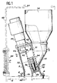
- FIG. 1 An example of implementation of the crusher according to the invention is shown in FIG. 1.
- the crusher firstly comprises a body 2, the main part of which is substantially cylindrical.
- This body 2 is fixed to a frame 4 by lugs 6 by means of screws 8.
- An inlet 10 is provided on the side wall of said body. The latter is extended projecting from said inlet orifice 10 so as to form a neck 12 channeling objects to be ground towards said orifice.
- a receptacle 14 is fixed on the neck 12 to receive said objects.
- An outlet orifice 15 is formed in a lower face of the body 2. It allows the evacuation of the crushed objects.
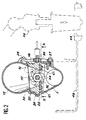
- An opening 16 (FIG. 2) is made in the side wall of the body 2. It allows the introduction and the exit of a drawer 18 in the body 2.
- This drawer 18 slides on slides 20 formed in said body 2 of such so that, when the drawer 18 is fully inserted into the body 2 and in abutment therein, this drawer 18 is positioned fixedly ( Figures 1 and 2).
- a straight boss 22 is formed on the slide 18 on the face of the latter which first penetrates into the body 2, said boss 22 being able to collaborate with a straight groove 24 formed in the opposite body 2 of the opening 16.
- a removable bar 26 is rotatably attached to the body 2 on one side of the opening 16 by a screw 27. On the other side of the latter, the bar 26 is capable of engage under a tab 28 allowing it to be held opposite the opening 16 and thus blocking the drawer 18 in the body 2. It suffices to rotate the bar by an angle sufficient to disengage the opening 16 and release the drawer.
- a passage 30 is formed in the drawer 18 so as to come in the extension of the inlet orifice 10 and the neck 12, the outlet orifice 15 then being disposed opposite the inlet orifice 10 and below said passage 30.
- a grinding tool 32 is disposed in this passage 30. It comprises a stack of cutter discs 34 secured to a common axis 36. This axis 36 is rotatably supported along a geometric axis slightly inclined relative to the vertical (FIG. 1) by two bearings 38, 40 housed in the drawer 18. A pinion 42 is fixed on the upper end of said axis 36. A double comb 61 bolted by screws 62 to the drawer 18 has teeth 63 which occupy, as can be seen in FIG. 3, the space between each disc cutter 34, which leads to more efficient grinding. Conveniently, the disc cutters 34 have teeth offset angularly and gradually along said axis 36 so as to describe a downward spiral with respect to the cutting direction of the grinding tool. This arrangement allows ob jets to be ground to be drawn to descend downward.
- a motor 44 for example pneumatic, is fixed on an upper face of the body 2.
- This motor has at the end of the shaft a pinion 46 able to pass through a hole made in said upper face of the body 2 and to mesh with the pinion 42 When the motor 44 is in place, it rotates the grinding tool 32.
- the crusher according to the invention is arranged for example in a closed enclosure 48 whose frame 4 constitutes the floor.
- This enclosure 48 has an opening 50 facing the receptacle 14, allowing the introduction of the objects to be ground into the crusher; an opening 52 facing the outlet 15 allowing the evacuation of the crushed objects; and an airlock 54 allowing the introduction and the exit of elements of the mill to be replaced.
- a manipulator arm 56 is for example disposed in the enclosure 48 ( Figure 2).
- One of the objects of the invention is to provide a crusher whose constituent elements are easily removable and manipulable.
- the motor 44, the receptacle 14, the drawer 18 and the grinding tool 32 are easily manipulated.
- the arm 56 after having turned the bar 26 (in dashed lines), withdraws the drawer 18 from the body 2 and can thus bring it out of the enclosure 48 by the airlock 54.
- the same operation, performed in reverse, allows the drawer 18 to be replaced with a re-sharpened grinding tool.
- the arm 56 can dismantle the motor, in the event of a breakdown for example, and replace it.
- Another object of the invention is to provide an efficient grinder.
- the inclined axis 36 and the offset of the teeth of the disc cutters 34 cooperate and allow efficient grinding of the objects without plug phenomenon, as well as rapid evacuation.
- the shape of the drawer can be adapted to needs: one or more tools, one or more drive motors.
Landscapes
- Engineering & Computer Science (AREA)
- Food Science & Technology (AREA)
- Crushing And Pulverization Processes (AREA)
Description
- La présente invention a pour objet un broyeur démontable. Elle s'applique notamment au broyage d'objets contaminés, par exemple des récipients chimiques ou radioactifs en verre ou en plastique dans une enceinte close.
- Le stockage dans des fûts et le retraitement d'objets tels que des flacons en verre ou en plastique sont optimisés lorsque ceux-ci sont broyés. L'opération de broyage devient délicate lorsque ces flacons ont contenu des substances chimiques ou radioactives nuisibles. Il est nécessaire alors d'opérer dans une enceinte close où toutes les manoeuvres de fonctionnement, de nettoyage, de réparations, ... sont effectuées à distance.
- Les différents broyeurs connus jusqu'à ce jour sont généralement du type à marteaux et à fonctionnement manuel. La manipulation est pénible et longue pour les utilisateurs et les objets ne sont pas broyés de façon efficace en ce qui concerne leur volume de stockage dans des fûts. De plus ils sont difficilement démontables et télémanipulables, surtout en ce qui concerne le remplacement de l'outil de broyage.
- L'invention concerne un broyeur démontable pour petits objets de verre ou en plastique rigide, efficace, fiable et robuste, autorisant un démontage et une télémanipulation faciles de ses éléments constitutifs. A cet effet, il comporte un corps sensiblement cylindrique dont la paroi latérale est pourvue d'un orifice d'entrée des objets à broyer et dont l'extrémité inférieure est munie d'un orifice de sortie de débris d'objets broyés, et un outil de broyage disposé entre l'orifice d'entrée et l'orifice de sortie et assujetti à un axe, l'outil de broyage présentant des dents aptes à broyer lesdits objets puis à entraîner les débris d'ob jets broyés vers ledit orifice de sortie et l'axe étant entraîné en rotation par des moyens d'entraînement (DE-A 2 338 398).
- Conformément à l'invention ledit axe est monté dans un tiroir logé de manière démontable dans le corps.
- Avantageusement, ledit tiroir à coulissement latéral est logé dans ledit corps au moyen de glissières ménagées dans celui-ci et une barrette amovible assure le maintien en position de fonctionnement du tiroir.
- Commodément, I'axe est légèrement incliné par rapport à la verticale, et l'outil de broyage est constitué par un empilement de fraises-disques possédant des dents décalées angulairement progressivement le long dudit axe et décrivant une spirale descendante par rapport au sens de coupe dudit outil de broyage.
- De toutes façons, l'invention sera mieux comprise en se référant la description qui suit d'un exemple de mise en oeuvre donné à titre illustratif et non limitatif, en référence aux figures annexées, sur lesquelles :
- - la figure 1 représente, en coupe longitudinale, le broyeur selon l'invention,
- - la figure 2 représente, en coupe suivant la ligne A-A de la figure 1, le broyeur selon l'invention, et
- - la figure 3 représente, en coupe partielle selon la ligne B-B de la figure 2, le broyeur selon l'invention.
- Un exemple de mise en oeuvre du broyeur selon l'invention est représenté sur la figure 1. Le broyeur comporte tout d'abord un corps 2 dont la partie principale est sensiblement cylindrique. Ce corps 2 est fixé sur un bâti 4 par des pattes 6 au moyen de vis 8.
- Un orifice d'entrée 10 est ménagé sur la paroi latérale dudit corps. Celui-ci se prolonge en saillie vis-à-vis dudit orifice d'entrée 10 de façon à former un goulet 12 canalisant des objets à broyer vers ledit orifice.
- Un réceptacle 14 est fixé sur le goulet 12 pour recevoir lesdits objets.
- Un orifice de sortie 15 est ménagé dans une face inférieure du corps 2. Il permet l'évacuation des objets broyés.
- Une ouverture 16 (figure 2) est ménagée dans la paroi latérale du corps 2. Elle permet l'introduction et la sortie d'un tiroir 18 dans le corps 2. Ce tiroir 18 coulisse sur des glissières 20 formées dans ledit corps 2 de telle façon que, lorsque le tiroir 18 est complètement enfoncé dans le corps 2 et en butée dans celui-ci, ce tiroir 18 est positionné fixement (figures 1 et 2). Par exemple, un bossage 22 rectiligne est formé sur le tiroir 18 sur la face de celui-ci qui pénètre en premier dans le corps 2, ledit bossage 22 étant apte à collaborer avec une rainure 24 rectiligne formée dans le corps 2 à l'opposé de l'ouverture 16. Lorsque le tiroir 18 est en butée dans la rainure 24 et en appui sur les glissières 20, il est positionné fixement sauf dans la direction du coulissement entrée-sortie du tiroir dans le corps. Afin de bloquer ce tiroir en position, une barrette 26 amovible est fixée à rotation sur le corps 2 d'un côté de l'ouverture 16 par une vis 27. De l'autre côté de celle-ci, la barrette 26 est apte à s'engager sous une patte 28 permettant son maintien en face de l'ouverture 16 et bloquant ainsi le tiroir 18 dans le corps 2. Il suffit de tourner la barrette d'un angle suffisant pour dégager l'ouverture 16 et libérer le tiroir.
- Un passage 30 est formé dans le tiroir 18 de façon à venir dans le prolongement de l'orifice d'entrée 10 et du goulet 12, l'orifice de sortie 15 étant alors disposé à l'opposé de l'orifice d'entrée 10 et en-dessous dudit passage 30.
- Un outil de broyage 32 est disposé dans ce passage 30. Il comporte un empilement de fraises-disques 34 assujetties à un axe 36 commun. Cet axe 36 est supporté à rotation selon un axe géométrique lè- gèrement incliné par rapport à la verticale (figure 1) par deux paliers 38, 40 logés dans le tiroir 18. Un pignon 42 est fixé sur l'extrémité supérieure dudit axe 36. Un doublé peigne 61 boulonné par des vis 62 au tiroir 18 possède des dents 63 qui occupent, comme on le voit figure 3, l'espace entre chaque fraise-disque 34, ce qui conduit à un broyage plus efficace. Commodément, les fraises-disques 34 possèdent des dents décalées angulairement et progressivement le long dudit axe 36 de façon à décrire une spirale descendante par rapport au sens de coupe de l'outil de broyage. Cette disposition permet aux objets à broyer d'être entraînés à descendre vers le bas.
- Un moteur 44, par exemple pneumatique, est fixé sur une face supérieure du corps 2. Ce moteur possède en bout d'arbre un pignon 46 apte à passer par un trou ménagé dans ladite face supérieure du corps 2 et à engrener avec le pignon 42. Lorsque le moteur 44 est en place, il entraîne en rotation l'outil de broyage 32.
- Le broyeur selon l'invention est disposé par exemple dans une enceinte close 48 dont le bâti 4 constitue le plancher. Cette enceinte 48 comporte une ouverture 50 face au réceptacle 14, permettant l'introduction des objets à broyer dans le broyeur ; une ouverture 52 face à l'orifice de sortie 15 permettant l'évacuation des objets broyés ; et un sas 54 permettant l'introduction et la sortie d'éléments du broyeur à remplacer.
- Un bras télémanipulateur 56 est par exemple disposé dans l'enceinte 48 (figure 2).
- Un des objets de l'invention est de proposer un broyeur dont les éléments constitutifs sont facilement démontables et télémanipulables. A cet effet, le moteur 44, le réceptacle 14, le tiroir 18 et l'outil de broyage 32 sont facilement télémanipulables. Comme le représente la figure 2 en exemple, le bras 56, après avoir tourné la barrette 26 (en traits mixtes), retire le tiroir 18 du corps 2 et peut ainsi le faire sortir de l'enceinte 48 par le sas 54. La même opération, effectuée en sens inverse, permet la remise en place du tiroir 18 avec un outil de broyage réaiguisé.
- De la même façon, le bras 56 peut démonter le moteur, en cas de panne par exemple, et le remplacer.
- Un autre objet de l'invention est de proposer un broyeur efficace. A cet effet, l'axe 36 incliné et le décalage des dents des fraises-disques 34 coopèrent et permettent un broyage efficace des objets sans phénomène de bouchon, ainsi qu'une évacuation rapide.
- Bien entendu, la description ci-dessus n'a été donné qu'à titre d'exemple, toutes modifications dans les formes de réalisation peuvent être envisagées sans modifier le principe fondamental de l'invention.
- On peut prévoir par exemple un tiroir muni de deux outils de broyage parallèles entraînés par le même moteur. La forme du tiroir peut être adaptée aux besoins : un ou plusieurs outils, un ou plusieurs moteurs d'entraînement.
Claims (3)
Applications Claiming Priority (2)
| Application Number | Priority Date | Filing Date | Title |
|---|---|---|---|
| FR8514672A FR2588198B1 (fr) | 1985-10-03 | 1985-10-03 | Broyeur demontable pour petits objets de verre ou en plastique rigide |
| FR8514672 | 1985-10-03 |
Publications (3)
| Publication Number | Publication Date |
|---|---|
| EP0220100A2 EP0220100A2 (fr) | 1987-04-29 |
| EP0220100A3 EP0220100A3 (en) | 1988-10-05 |
| EP0220100B1 true EP0220100B1 (fr) | 1990-07-11 |
Family
ID=9323501
Family Applications (1)
| Application Number | Title | Priority Date | Filing Date |
|---|---|---|---|
| EP19860402132 Expired - Lifetime EP0220100B1 (fr) | 1985-10-03 | 1986-09-30 | Broyeur démontable pour petits objets de verre ou en plastique rigide |
Country Status (3)
| Country | Link |
|---|---|
| EP (1) | EP0220100B1 (fr) |
| DE (1) | DE3672558D1 (fr) |
| FR (1) | FR2588198B1 (fr) |
Families Citing this family (2)
| Publication number | Priority date | Publication date | Assignee | Title |
|---|---|---|---|---|
| EP0720865A1 (fr) * | 1995-01-06 | 1996-07-10 | Naamloze Vennootschap De Pecker | Dispositif de déchiquetage |
| DE19524521A1 (de) * | 1995-07-05 | 1997-01-09 | Bosch Gmbh Robert | Häcksler |
Family Cites Families (2)
| Publication number | Priority date | Publication date | Assignee | Title |
|---|---|---|---|---|
| DE696749C (de) * | 1939-04-23 | 1940-09-28 | Verwertung Fauth Scher Patente | Vorrichtung zum Zerkleinern von Walknochen, Walspeck, harten OElfruechten u. dgl. |
| DE2338398A1 (de) * | 1973-01-26 | 1974-08-01 | Dieter Schlehan | Verfahren und vorrichtung zum zerkleinern von hohlem fuellgut |
-
1985
- 1985-10-03 FR FR8514672A patent/FR2588198B1/fr not_active Expired
-
1986
- 1986-09-30 EP EP19860402132 patent/EP0220100B1/fr not_active Expired - Lifetime
- 1986-09-30 DE DE8686402132T patent/DE3672558D1/de not_active Expired - Lifetime
Also Published As
| Publication number | Publication date |
|---|---|
| EP0220100A3 (en) | 1988-10-05 |
| FR2588198A1 (fr) | 1987-04-10 |
| EP0220100A2 (fr) | 1987-04-29 |
| DE3672558D1 (de) | 1990-08-16 |
| FR2588198B1 (fr) | 1989-04-28 |
Similar Documents
| Publication | Publication Date | Title |
|---|---|---|
| FR2467018A1 (fr) | Marteau pour broyeur a marteaux, en particulier pour appareils dechiqueteurs | |
| FR2542632A1 (fr) | Broyeur pour dechets | |
| CH650431A5 (fr) | Outil de coupe a couteaux amovibles. | |
| EP0620043A2 (fr) | Appareil pour fragmenter des objets solides | |
| EP0069721A2 (fr) | Broyeur de déchets à taille hélicoidale | |
| EP2859823B1 (fr) | Accessoire pour découper des aliments comprenant des moyens sécurisés d'entraînement en rotation d'un outil de coupe | |
| FR2508345A1 (fr) | ||
| EP0220100B1 (fr) | Broyeur démontable pour petits objets de verre ou en plastique rigide | |
| EP2853184B1 (fr) | Accessoire pour découper des aliments dont un outil de coupe secondaire fixe comprend des moyens de préhension | |
| EP1776856B1 (fr) | Dispositif de decoupe de vegetaux | |
| EP0420731A1 (fr) | Broyeur-déchiqueteur à déchets à couteaux | |
| FR2462957A1 (fr) | Systeme transporteur compact pour collecteur des copeaux metalliques provenant de machines de fraisage | |
| EP2859824B1 (fr) | Accessoire pour découper des aliments en morceaux | |
| FR2785205A1 (fr) | Dispositif de broyage de dechets | |
| FR2635022A1 (fr) | Broyeur a ferrailles, notamment a ferrailles d'incineration | |
| FR2851481A1 (fr) | Dispositif separateur des elements durs pour broyeur utilise dans le domaine de l'industrie alimentaire et plus particulierement de la decoupe de la viande | |
| EP1055459B1 (fr) | Dispsitif d'introduction forcée de pièces plastique ou de déchets de toutes dimentions dans toutes types de machines à broyer | |
| EP0412004A2 (fr) | Broyeur rotatif et enceinte de manipulation d'objets contenant des éléments toxiques ou radio-actifs | |
| EP3967133A1 (fr) | Carter de dispositif de lamier d'élagage, et lamier équipé d'un tel carter | |
| EP2949438B1 (fr) | Broyeur de végétaux pour réaliser des particules calibrées | |
| BE1032619B1 (fr) | Repartiteur a ouverture rapide | |
| FR2464097A1 (fr) | Appareil de desagregation de dechets par broyage et dechiquetage combines | |
| FR2737137A1 (fr) | Dispositif pour le dechiquetage d'objets et de dechets industriels tels que des cartons en vue de reduire leur volume | |
| FR2691079A1 (fr) | Broyeur compact notamment pour déchets. | |
| FR2796870A1 (fr) | Dispositif de decoupe de filtres a huile, notamment de vehicules automobiles |
Legal Events
| Date | Code | Title | Description |
|---|---|---|---|
| PUAI | Public reference made under article 153(3) epc to a published international application that has entered the european phase |
Free format text: ORIGINAL CODE: 0009012 |
|
| AK | Designated contracting states |
Kind code of ref document: A2 Designated state(s): BE CH DE FR GB IT LI NL |
|
| PUAL | Search report despatched |
Free format text: ORIGINAL CODE: 0009013 |
|
| AK | Designated contracting states |
Kind code of ref document: A3 Designated state(s): BE CH DE FR GB IT LI NL |
|
| 17P | Request for examination filed |
Effective date: 19890309 |
|
| 17Q | First examination report despatched |
Effective date: 19890913 |
|
| GRAA | (expected) grant |
Free format text: ORIGINAL CODE: 0009210 |
|
| AK | Designated contracting states |
Kind code of ref document: B1 Designated state(s): BE CH DE FR GB IT LI NL |
|
| REF | Corresponds to: |
Ref document number: 3672558 Country of ref document: DE Date of ref document: 19900816 |
|
| ITF | It: translation for a ep patent filed | ||
| GBT | Gb: translation of ep patent filed (gb section 77(6)(a)/1977) | ||
| PLBE | No opposition filed within time limit |
Free format text: ORIGINAL CODE: 0009261 |
|
| STAA | Information on the status of an ep patent application or granted ep patent |
Free format text: STATUS: NO OPPOSITION FILED WITHIN TIME LIMIT |
|
| 26N | No opposition filed | ||
| ITTA | It: last paid annual fee | ||
| PGFP | Annual fee paid to national office [announced via postgrant information from national office to epo] |
Ref country code: BE Payment date: 19960903 Year of fee payment: 11 |
|
| PGFP | Annual fee paid to national office [announced via postgrant information from national office to epo] |
Ref country code: GB Payment date: 19960919 Year of fee payment: 11 |
|
| PGFP | Annual fee paid to national office [announced via postgrant information from national office to epo] |
Ref country code: CH Payment date: 19960925 Year of fee payment: 11 |
|
| PGFP | Annual fee paid to national office [announced via postgrant information from national office to epo] |
Ref country code: NL Payment date: 19960926 Year of fee payment: 11 |
|
| PGFP | Annual fee paid to national office [announced via postgrant information from national office to epo] |
Ref country code: FR Payment date: 19960927 Year of fee payment: 11 |
|
| PGFP | Annual fee paid to national office [announced via postgrant information from national office to epo] |
Ref country code: DE Payment date: 19961007 Year of fee payment: 11 |
|
| PG25 | Lapsed in a contracting state [announced via postgrant information from national office to epo] |
Ref country code: LI Free format text: LAPSE BECAUSE OF NON-PAYMENT OF DUE FEES Effective date: 19970930 Ref country code: GB Free format text: LAPSE BECAUSE OF NON-PAYMENT OF DUE FEES Effective date: 19970930 Ref country code: FR Free format text: THE PATENT HAS BEEN ANNULLED BY A DECISION OF A NATIONAL AUTHORITY Effective date: 19970930 Ref country code: CH Free format text: LAPSE BECAUSE OF NON-PAYMENT OF DUE FEES Effective date: 19970930 Ref country code: BE Free format text: LAPSE BECAUSE OF NON-PAYMENT OF DUE FEES Effective date: 19970930 |
|
| BERE | Be: lapsed |
Owner name: COMMISSARIAT A L'ENERGIE ATOMIQUE Effective date: 19970930 |
|
| PG25 | Lapsed in a contracting state [announced via postgrant information from national office to epo] |
Ref country code: NL Free format text: LAPSE BECAUSE OF NON-PAYMENT OF DUE FEES Effective date: 19980401 |
|
| REG | Reference to a national code |
Ref country code: CH Ref legal event code: PL |
|
| GBPC | Gb: european patent ceased through non-payment of renewal fee |
Effective date: 19970930 |
|
| NLV4 | Nl: lapsed or anulled due to non-payment of the annual fee |
Effective date: 19980401 |
|
| PG25 | Lapsed in a contracting state [announced via postgrant information from national office to epo] |
Ref country code: DE Free format text: LAPSE BECAUSE OF NON-PAYMENT OF DUE FEES Effective date: 19980603 |
|
| REG | Reference to a national code |
Ref country code: FR Ref legal event code: ST |
|
| PG25 | Lapsed in a contracting state [announced via postgrant information from national office to epo] |
Ref country code: IT Free format text: LAPSE BECAUSE OF NON-PAYMENT OF DUE FEES;WARNING: LAPSES OF ITALIAN PATENTS WITH EFFECTIVE DATE BEFORE 2007 MAY HAVE OCCURRED AT ANY TIME BEFORE 2007. THE CORRECT EFFECTIVE DATE MAY BE DIFFERENT FROM THE ONE RECORDED. Effective date: 20050930 |