EP0219882B1 - Procédé et dispositif automatique de nettoyage d'un échangeur de chaleur pour fluides gazeux - Google Patents
Procédé et dispositif automatique de nettoyage d'un échangeur de chaleur pour fluides gazeux Download PDFInfo
- Publication number
- EP0219882B1 EP0219882B1 EP86114805A EP86114805A EP0219882B1 EP 0219882 B1 EP0219882 B1 EP 0219882B1 EP 86114805 A EP86114805 A EP 86114805A EP 86114805 A EP86114805 A EP 86114805A EP 0219882 B1 EP0219882 B1 EP 0219882B1
- Authority
- EP
- European Patent Office
- Prior art keywords
- channels
- injection
- elastic members
- additional
- exchanger
- Prior art date
- Legal status (The legal status is an assumption and is not a legal conclusion. Google has not performed a legal analysis and makes no representation as to the accuracy of the status listed.)
- Expired
Links
- 238000004140 cleaning Methods 0.000 title claims abstract description 27
- 239000012530 fluid Substances 0.000 title claims abstract description 24
- 238000000034 method Methods 0.000 title claims description 15
- 230000008569 process Effects 0.000 title claims description 9
- 238000002347 injection Methods 0.000 claims abstract description 38
- 239000007924 injection Substances 0.000 claims abstract description 38
- 230000001939 inductive effect Effects 0.000 claims abstract description 3
- 239000002184 metal Substances 0.000 claims description 7
- 238000011144 upstream manufacturing Methods 0.000 claims description 4
- 239000007789 gas Substances 0.000 description 38
- 230000000737 periodic effect Effects 0.000 description 6
- 239000007788 liquid Substances 0.000 description 5
- 238000007790 scraping Methods 0.000 description 5
- 239000007787 solid Substances 0.000 description 5
- 238000012423 maintenance Methods 0.000 description 4
- 239000002245 particle Substances 0.000 description 4
- 230000000694 effects Effects 0.000 description 3
- 238000000605 extraction Methods 0.000 description 3
- 230000009467 reduction Effects 0.000 description 3
- 238000004804 winding Methods 0.000 description 3
- 230000009471 action Effects 0.000 description 2
- 230000008021 deposition Effects 0.000 description 2
- 239000000428 dust Substances 0.000 description 2
- 238000003780 insertion Methods 0.000 description 2
- 230000037431 insertion Effects 0.000 description 2
- 238000003466 welding Methods 0.000 description 2
- 230000006978 adaptation Effects 0.000 description 1
- 238000004026 adhesive bonding Methods 0.000 description 1
- 238000013019 agitation Methods 0.000 description 1
- 238000010276 construction Methods 0.000 description 1
- 238000007796 conventional method Methods 0.000 description 1
- 238000001816 cooling Methods 0.000 description 1
- 239000000112 cooling gas Substances 0.000 description 1
- 238000013461 design Methods 0.000 description 1
- 230000006866 deterioration Effects 0.000 description 1
- 230000037213 diet Effects 0.000 description 1
- 235000005911 diet Nutrition 0.000 description 1
- 230000003628 erosive effect Effects 0.000 description 1
- 230000005284 excitation Effects 0.000 description 1
- 230000005484 gravity Effects 0.000 description 1
- 238000009434 installation Methods 0.000 description 1
- 230000007246 mechanism Effects 0.000 description 1
- 238000012986 modification Methods 0.000 description 1
- 230000004048 modification Effects 0.000 description 1
- 238000013021 overheating Methods 0.000 description 1
- 230000000149 penetrating effect Effects 0.000 description 1
- 230000000135 prohibitive effect Effects 0.000 description 1
- 238000011084 recovery Methods 0.000 description 1
- 230000003252 repetitive effect Effects 0.000 description 1
- 239000000779 smoke Substances 0.000 description 1
- 238000003756 stirring Methods 0.000 description 1
- 239000000126 substance Substances 0.000 description 1
- 238000010408 sweeping Methods 0.000 description 1
- 238000009827 uniform distribution Methods 0.000 description 1
- XLYOFNOQVPJJNP-UHFFFAOYSA-N water Substances O XLYOFNOQVPJJNP-UHFFFAOYSA-N 0.000 description 1
Images


Classifications
-
- F—MECHANICAL ENGINEERING; LIGHTING; HEATING; WEAPONS; BLASTING
- F28—HEAT EXCHANGE IN GENERAL
- F28G—CLEANING OF INTERNAL OR EXTERNAL SURFACES OF HEAT-EXCHANGE OR HEAT-TRANSFER CONDUITS, e.g. WATER TUBES OR BOILERS
- F28G7/00—Cleaning by vibration or pressure waves
-
- F—MECHANICAL ENGINEERING; LIGHTING; HEATING; WEAPONS; BLASTING
- F28—HEAT EXCHANGE IN GENERAL
- F28G—CLEANING OF INTERNAL OR EXTERNAL SURFACES OF HEAT-EXCHANGE OR HEAT-TRANSFER CONDUITS, e.g. WATER TUBES OR BOILERS
- F28G1/00—Non-rotary, e.g. reciprocated, appliances
- F28G1/06—Non-rotary, e.g. reciprocated, appliances having coiled wire tools, i.e. basket type
Definitions
- the present invention relates to a method and an automatic device for periodically cleaning the surfaces of a heat exchanger intended to treat gaseous fluids flowing in vertical channels defined between said surfaces.
- Another means of combating fouling and clogging is to provide cleaning of the inside of the tubes.
- Devices for this purpose have been provided, in particular for tubular heat exchangers intended for the treatment of liquids.
- FR-A-2 435 292 also suitable in the case of a heat exchanger for the treatment of liquids, uses a mechanical device to periodically stretch a helical spring whose function is to scrape the substances deposited along the walls, thus preventing their deterioration by local overheating. It is recommended to use a tight fit along the wall of the tube.
- the present invention relates to an automatic method and device for periodic cleaning of the internal surfaces of a heat exchanger for gaseous fluids which makes it possible to obtain a vibration of elastic scraping elements placed inside the channels of the heat exchanger, and this by simple pneumatically actuated means, in order to solve the problems posed by the adaptation of known cleaning devices to heat exchangers intended to treat gaseous fluids.
- the automatic method of periodic cleaning of the surfaces of a heat exchanger for gaseous fluids flowing in vertical channels between said surfaces makes use of elastic elements permanently arranged in said channels and capable of being vibrated to perform cleaning of said surfaces.
- the elastic elements are vibrated successively for at least one group of channels of the heat exchanger, by means of an injection of an additional compressed gas in a position such that it induces in said group of channels a flow of gaseous fluid coming from the exchanger.
- the additional gas injection control can be done manually intermittently, or according to a sequence determined for each group of channels of the exchanger under the control of an automatic control system.
- the injection of the additional gas under pressure can be done in the axis or in the plane of symmetry of the channels, or even in an inclined manner depending on the applications.
- the injection of the additional compressed gas is preferably carried out by means of nozzles placed in a position upstream of the mouth of each channel of the heat exchanger.
- the invention also relates to an automatic device for periodically cleaning the surfaces of a heat exchanger for gaseous fluids which allows the implementation of the method of the invention.
- the device of the invention comprises injection pipes for additional compressed gas opening upstream, in front of the openings of the channel groups and an injection control device suitable for successively and periodically controlling for each group of channels, an injection of additional compressed gas inducing in the group of channels a flow of gaseous fluid coming from the exchanger, thus causing the vibration of the elastic elements being in the group of channels.
- the elastic elements are preferably fixed at their two ends in the vicinity of the two ends of the channels.
- the elastic elements may only be fixed at their upper end, close to the opening, the lower end of the elastic elements then being free.
- the injection pipes preferably have injection nozzles which direct the flow of additional compressed gas towards the upper opening of the channels. These nozzles can also serve as a fixing for the upper part of the elastic elements, either directly or by means of additional elements integral with the nozzles or fixed to the nozzles.
- the elastic elements are arranged in the vertical channels of the heat exchanger in the immediate vicinity of their internal walls, without however coming into contact with said walls during normal operation of the exchanger, that is to say outside cleaning periods.
- the elastic elements therefore act as turbulators disturbing the boundary layer in the vicinity of the internal walls of the channels, which makes it possible to circulate the gas flow at a low speed which is preferably between approximately 8 and 12 m / second, and more particularly between approximately 8 and 10 m / second.
- the elastic elements consist of metal wires wound in a helix.
- metal wires provided with a plurality of blades extending radially, advantageously aerodynamically profiled, so as to vibrate the whole of the elastic element by the action of the gas flow induced by the additional compressed gas from the injection lines.
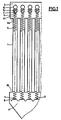
- the heat exchanger is of the cross-flow tubular type in which hot and dusty gases flow inside vertical tubes 1, preferably from top to bottom. low.
- the cooling air flows transversely to the direction of the hot and dusty gases, outside of the tubes 1 and between them.
- the invention could also be applied, without notable modifications, to an exchanger of the tube-shell type with flow parallel to the tubes of the cooling gases, or to another type, and in particular to a heat exchanger. with plates.
- the tubes 1 are fixed to the upper 2a and lower 2b head plates by welding according to a conventional method in the construction of exchangers of this type.
- the tubes 1 thus communicate with an upper plenum 3 which is used for the admission or extraction of hot and dusty gases through an intake or extraction orifice which is not shown in the figures, and with a lower plenum 4 comprising an extraction or admission orifice also not shown.
- the lower plenum 4 preferably has, as illustrated in FIG. 1, the shape of a hopper making it possible to facilitate the recovery of the solid particles which will settle there during the cleaning operations.
- the dimensioning of the gas passage sections is chosen so that a flow speed of between approximately 8 and 12 m / second, and preferably approximately 8 and 10 m / second, is obtained. It is indeed advisable not to adopt a too high flow speed, in order not to create exaggerated pressure drops. Furthermore, a flow rate that is too low would cause prohibitive bulk for the entire apparatus.
- the choice of the diameter of the tubes is made so as to allow the passage of gases with the suitable flow speed which has just been mentioned, while allowing the insertion of the elastic cleaning elements.
- the elastic elements are formed in the example illustrated in Figures 1 and 2 by a metal wire 5 wound in a helix and forming a spring.
- the springs 5 are rigidly fixed at their upper 6 and lower 7 ends, which both protrude from the upper and lower ends of the tubes 1.
- the lower ends 7 of the springs 5 are fixed to a grid 8 itself rigidly mounted by means not illustrated in the figures, in the lower plenum 4.
- the grid 8 has a mesh identical to that of the axes of the tubes 1 of the exchanger. It will however be understood that a different attachment could perfectly well be envisaged.
- the lower part 7 of the spring 5 is fixed by means of hooks 9 allowing easy disassembly.
- hooks 9 allowing easy disassembly.
- other means could be used, and in particular a bolting or pinning fastening, insofar as easy disassembly remains possible.
- injection nozzles 10 for an additional compressed gas which can for example be compressed air or steam pressurized water.
- the nozzles 10 have ends of small diameter which can be for example between 4 and 10 mm approximately, it being understood that the choice of the diameter of the injection nozzle depends on the diameter of the tubes 1 of the exchanger.
- the nozzles 10 are centered on the axes of the tubes 1 and placed at a certain distance above the opening of the tubes 1. It would be possible, in a variant, for the axis of the nozzles 10 to have a certain inclination relative to the 'axis of the tubes 1, which would then direct the compressed additional gas jet towards the periphery of the elastic elements 5, causing a different excitation.
- each injection pipe 12 equipped with its plurality of vertical tubes 11 and injection nozzles 10, allows the injection of gas into a row of tubes 1 ( Figure 2).
- a control valve 14 which can be actuated manually or by means of a solenoid valve controlled by an automatic mechanism, allows the periodically controlled injection of the additional compressed gas contained in the reservoir 13, for this row of tubes 1.
- FIG. 3 there is seen a first embodiment of such an attachment.
- the injection tube 11 is provided with longitudinal fins 15 in which are made perforations 16 allowing the passage and the winding of the upper end of the spring 5.
- FIG. 4 shows an alternative embodiment in which the spring 5 is terminated by a winding 17 of smaller diameter than the spring 5, the winding 17 being threaded on the end of the injection tube 11 and blocked by a clamping element 18. It will of course be noted that 'it would be perfectly possible to fix the upper ends of the springs 5 by other means, for example directly on the injection pipe 12, or else on a separate support rigidly mounted in the upper plenum 3.
- the device of the invention operates in the following manner.
- a gas is injected into a row of tubes 1 additional tablet at a pressure of the order of 2 to 6 bars via the nozzles 10.
- This injection which is carried out for a relatively short duration, for example between 1 / 10th of a second and a few seconds, instantly induces a flow of fluid gas from the upper plenum 3 and the tubes 1 of the adjacent rows.
- This induced gaseous fluid flow rate is of the order of four to six times the flow rate of the additional compressed gas injected through the nozzles 10.
- the flow speed thus created inside the tubes 1 is therefore very high.
- the amount of movement thus provided is communicated to the springs 5 and the resulting agitation is damped in the flow and along the walls of the tubes 1 by impact and scraping, which results in cleaning and maintenance of the state. internal surfaces of the tubes 1 of the heat exchanger.
- FIG. 5 illustrates a variant of the device of the invention in which the upper end of each tube 1 of the exchanger is fitted with a mouth piece 19 partially penetrating inside the tube 1.
- the piece of mouth 19 can be fixed to tube 1 by threading as illustrated in FIG. 5, or by any other means such as snap-fastening, welding, gluing, etc.
- the mouthpiece 19 is profiled in the manner of a nozzle convergent, so as to induce a greater flow of gaseous fluid under the effect of the injection of the additional compressed gas by the nozzles 10 placed as before at a certain distance from the mouth of the tubes 1. It is thus possible to further reduce the flow rate of the additional compressed gas necessary for the periodic cleaning operation.
- FIG. 6 schematically shows an elastic element of different structure which can be used in the context of the invention.
- the blades 21 then cause the cleaning by impacts and scraping as previously.
- the elastic element constituted by the spring 5 or by the cable 20 provided with the fins 21, or even by any other equivalent means be placed inside the tube 1 or of the vertical channel of the exchanger, so as to be in close proximity to its internal walls, without however coming into contact with said walls during normal operation of the heat exchanger outside of the cleaning periods.
- the boundary layer is effectively disturbed by portions of the elastic element located in the vicinity of the internal walls of the tubes 1 and cleaning is better ensured during the injection of compressed gas.
- the elastic elements have been rigidly fixed at their upper and lower ends. It will however be understood that it would be possible in a variant not to fix the lower ends of the elastic elements. These then remain free of any hindrance in the vicinity of their lower end 7 and can somehow float in the gas flow. The vibration characteristics caused by the injection of additional compressed gas and the induced gas flow are then different and can be adapted to certain particular problems of clogging.
Landscapes
- Engineering & Computer Science (AREA)
- Chemical & Material Sciences (AREA)
- Combustion & Propulsion (AREA)
- Mechanical Engineering (AREA)
- General Engineering & Computer Science (AREA)
- Heat-Exchange Devices With Radiators And Conduit Assemblies (AREA)
- Cleaning In General (AREA)
- Cleaning And De-Greasing Of Metallic Materials By Chemical Methods (AREA)
- Cleaning By Liquid Or Steam (AREA)
- Vaporization, Distillation, Condensation, Sublimation, And Cold Traps (AREA)
- Physical Or Chemical Processes And Apparatus (AREA)
- Gas Separation By Absorption (AREA)
Priority Applications (1)
| Application Number | Priority Date | Filing Date | Title |
|---|---|---|---|
| AT86114805T ATE39284T1 (de) | 1985-10-25 | 1986-10-24 | Verfahren und automatische vorrichtung zum reinigen eines waermetauschers fuer gasfoermige fluide. |
Applications Claiming Priority (2)
| Application Number | Priority Date | Filing Date | Title |
|---|---|---|---|
| FR8515923 | 1985-10-25 | ||
| FR8515923A FR2589229B1 (fr) | 1985-10-25 | 1985-10-25 | Procede et dispositif automatique de nettoyage d'un echangeur de chaleur pour fluides gazeux |
Publications (2)
| Publication Number | Publication Date |
|---|---|
| EP0219882A1 EP0219882A1 (fr) | 1987-04-29 |
| EP0219882B1 true EP0219882B1 (fr) | 1988-12-14 |
Family
ID=9324227
Family Applications (1)
| Application Number | Title | Priority Date | Filing Date |
|---|---|---|---|
| EP86114805A Expired EP0219882B1 (fr) | 1985-10-25 | 1986-10-24 | Procédé et dispositif automatique de nettoyage d'un échangeur de chaleur pour fluides gazeux |
Country Status (16)
| Country | Link |
|---|---|
| US (1) | US4825940A (da) |
| EP (1) | EP0219882B1 (da) |
| JP (1) | JPS6325497A (da) |
| KR (1) | KR870004285A (da) |
| AT (1) | ATE39284T1 (da) |
| AU (1) | AU590344B2 (da) |
| BE (1) | BE903577A (da) |
| BR (1) | BR8605213A (da) |
| CA (1) | CA1272184A (da) |
| DE (1) | DE3661444D1 (da) |
| DK (1) | DK161857C (da) |
| ES (1) | ES2004834B3 (da) |
| FR (1) | FR2589229B1 (da) |
| GR (1) | GR3000009T3 (da) |
| NO (1) | NO167327C (da) |
| PT (1) | PT83596B (da) |
Cited By (1)
| Publication number | Priority date | Publication date | Assignee | Title |
|---|---|---|---|---|
| DE19740883C1 (de) * | 1997-09-16 | 1999-02-25 | Renzmann Und Gruenewald Gmbh | Wärmeaustauscher |
Families Citing this family (14)
| Publication number | Priority date | Publication date | Assignee | Title |
|---|---|---|---|---|
| JPH0672754B2 (ja) * | 1987-09-30 | 1994-09-14 | 株式会社ジャパンエナジー | 熱交換器の伝熱管におけるスケール等の付着防止装置 |
| FR2639425B1 (fr) * | 1988-11-18 | 1991-06-07 | Total France | Procede et dispositif de nettoyage d'un tube dans lequel circule un fluide, et utilisation dans les tubes d'echangeurs de chaleur |
| CA2100734C (en) * | 1993-07-16 | 1998-05-26 | Normand Verret | Heat exchanger for dusty environment |
| DE19544185C2 (de) * | 1995-11-28 | 1998-08-13 | Renzmann Und Gruenewald Gmbh | Wärmetauscher |
| DE19721927C1 (de) * | 1997-05-26 | 1999-02-25 | Renzmann Und Gruenewald Gmbh | Wärmetauscher |
| DE19723971C1 (de) * | 1997-06-06 | 1999-02-25 | Renzmann Und Gruenewald Gmbh | Wärmetauscher |
| US5799622A (en) * | 1997-06-30 | 1998-09-01 | Decker Manufacturing | Furnace heat exchanger tube cleaning system |
| FR2787564B1 (fr) * | 1998-12-22 | 2001-03-02 | Total Raffinage Distribution | Perfectionnements apportes aux tubes d'echangeurs thermiques, en vue d'eviter le colmatage de leur entree par des materiaux en suspension |
| US7093649B2 (en) * | 2004-02-10 | 2006-08-22 | Peter Dawson | Flat heat exchanger plate and bulk material heat exchanger using the same |
| FR2890162B1 (fr) * | 2005-08-30 | 2007-11-30 | Total France Sa | Dispositif reducteur d'encrassement d'un echangeur thermique tubulaire. |
| TWI428168B (zh) * | 2011-09-27 | 2014-03-01 | Wang Yung Chuan Lee | Anti - fouling device for membrane filter |
| AT517955B1 (de) * | 2016-05-18 | 2017-06-15 | Ökofen Forschungs- Und Entw M B H | Heizeinrichtung |
| CN108716805A (zh) * | 2018-07-02 | 2018-10-30 | 天津商业大学 | 自动除霜的绕片换热器 |
| EP3786561B1 (en) | 2019-09-02 | 2022-12-14 | Orion Engineered Carbons IP GmbH & Co. KG | Anti-fouling device for heat exchangers and its use |
Family Cites Families (10)
| Publication number | Priority date | Publication date | Assignee | Title |
|---|---|---|---|---|
| US2795400A (en) * | 1954-07-22 | 1957-06-11 | Air Preheater | Heat transfer elements for rotary regenerative heaters |
| FR1248787A (fr) * | 1959-03-13 | 1960-12-23 | Schmidt Sche Heissdampf | Dispositif de nettoyage des tubes d'échangeurs de chaleur sur la face située du côté des gaz de fumée |
| BE666832A (da) * | 1964-07-13 | |||
| US3364983A (en) * | 1965-01-04 | 1968-01-23 | Cabot Corp | Heat exchange process and apparatus |
| US3288204A (en) * | 1964-12-11 | 1966-11-29 | Air Preheater | Suspended chain matrix |
| JPS523903A (en) * | 1975-06-24 | 1977-01-12 | Kikan Buhin Seizo Kk | Smoke tube dust cleaner |
| DE2948201C2 (de) * | 1979-11-30 | 1985-09-26 | Degussa Ag, 6000 Frankfurt | Vorrichtung und Verfahren zum periodischen Abreinigen von Wärmeaustauscherrohren von Feststoffablagerungen und Verwendung dieser Vorrichtung |
| SU996841A1 (ru) * | 1981-03-04 | 1983-02-15 | за витель В. М- Климов | Устройство дл очистки трубок теплообменных аппаратов |
| US4583585A (en) * | 1981-07-22 | 1986-04-22 | Elf France | System for cleaning tube-type exchangers automatically during operation |
| SU1143964A1 (ru) * | 1983-07-27 | 1985-03-07 | Литовский Научно-Исследовательский Институт Механизации И Электрификации Сельского Хозяйства | Теплообменник |
-
1985
- 1985-10-25 FR FR8515923A patent/FR2589229B1/fr not_active Expired
- 1985-11-04 BE BE0/215816A patent/BE903577A/fr not_active IP Right Cessation
-
1986
- 1986-10-21 PT PT83596A patent/PT83596B/pt not_active IP Right Cessation
- 1986-10-24 US US06/922,903 patent/US4825940A/en not_active Expired - Fee Related
- 1986-10-24 AT AT86114805T patent/ATE39284T1/de not_active IP Right Cessation
- 1986-10-24 DK DK511686A patent/DK161857C/da not_active IP Right Cessation
- 1986-10-24 AU AU64379/86A patent/AU590344B2/en not_active Ceased
- 1986-10-24 ES ES86114805T patent/ES2004834B3/es not_active Expired
- 1986-10-24 JP JP61253510A patent/JPS6325497A/ja active Pending
- 1986-10-24 DE DE8686114805T patent/DE3661444D1/de not_active Expired
- 1986-10-24 BR BR8605213A patent/BR8605213A/pt not_active IP Right Cessation
- 1986-10-24 NO NO864267A patent/NO167327C/no unknown
- 1986-10-24 EP EP86114805A patent/EP0219882B1/fr not_active Expired
- 1986-10-25 KR KR1019860008959A patent/KR870004285A/ko not_active Withdrawn
- 1986-10-27 CA CA000521477A patent/CA1272184A/fr not_active Expired - Fee Related
-
1989
- 1989-03-10 GR GR88400009T patent/GR3000009T3/el unknown
Non-Patent Citations (1)
| Title |
|---|
| PATENTS ABSTRACTS OF JAPAN, vol. 1, no. 51, 18 mai 1977, page 252 M 77; & JP-A-52 3903 (KIKAN BUHIN SEIZO K.K.) 01-12-1977 * |
Cited By (1)
| Publication number | Priority date | Publication date | Assignee | Title |
|---|---|---|---|---|
| DE19740883C1 (de) * | 1997-09-16 | 1999-02-25 | Renzmann Und Gruenewald Gmbh | Wärmeaustauscher |
Also Published As
| Publication number | Publication date |
|---|---|
| DK511686A (da) | 1987-04-26 |
| KR870004285A (ko) | 1987-05-08 |
| DK161857B (da) | 1991-08-19 |
| EP0219882A1 (fr) | 1987-04-29 |
| DK511686D0 (da) | 1986-10-24 |
| CA1272184A (fr) | 1990-07-31 |
| NO864267D0 (no) | 1986-10-24 |
| PT83596A (fr) | 1986-11-01 |
| GR3000009T3 (en) | 1989-09-29 |
| BR8605213A (pt) | 1987-07-28 |
| NO167327C (no) | 1991-10-23 |
| NO864267L (no) | 1987-04-27 |
| DK161857C (da) | 1992-01-20 |
| BE903577A (fr) | 1986-05-05 |
| JPS6325497A (ja) | 1988-02-02 |
| US4825940A (en) | 1989-05-02 |
| FR2589229B1 (fr) | 1988-01-08 |
| ATE39284T1 (de) | 1988-12-15 |
| NO167327B (no) | 1991-07-15 |
| FR2589229A1 (fr) | 1987-04-30 |
| DE3661444D1 (en) | 1989-01-19 |
| AU6437986A (en) | 1987-04-30 |
| PT83596B (pt) | 1992-10-30 |
| ES2004834B3 (es) | 1989-12-01 |
| AU590344B2 (en) | 1989-11-02 |
Similar Documents
| Publication | Publication Date | Title |
|---|---|---|
| EP0219882B1 (fr) | Procédé et dispositif automatique de nettoyage d'un échangeur de chaleur pour fluides gazeux | |
| FR3029959A1 (fr) | Refroidissement de composants de moteur | |
| EP1800725B1 (fr) | Enceinte de traitement d'hydrocarbures comprenant un organe de déversement | |
| EP0369851B1 (fr) | Dispositif de nettoyage d'un tube dans lequel circule un fluide | |
| FR2598800A1 (fr) | Separateur de particules liquides a ailettes | |
| FR2562438A1 (fr) | Appareil d'evaporation a tube oscillant et repartiteur de fluide | |
| CA1285374C (fr) | Dispositif pour l'alimentation des ouvertures d'une grille de fluidisation en gaz de decolmatage | |
| EP0877222B1 (fr) | Dispositif d'injection de fluides sous pression dans un échangeur thermique à plaques et procédé de nettoyage d'un tel dispositif d'injection | |
| WO2000043304A1 (fr) | Dispositif de dispersion d'un materiau solide divise a l'interieur d'un recipient | |
| EP2755800A1 (fr) | Dispositif de projection de glace sèche, notamment de glace carbonique, et buse pour un tel dispositif | |
| EP1143153B1 (fr) | Té muni d'un dispositif pour diminuer les vibrations et les à-coups dans un réseau de conduit pour fluide gazeux, réseau de conduit équipé d'un tel té | |
| FR2774924A1 (fr) | Separateur pour melange triphasique destine a etre utilise sous le niveau de la mer | |
| FR2975754A1 (fr) | Chaudiere a vapeur avec insert | |
| EP3847342B1 (fr) | Boîtier d'alimentation en air sous pression d'un dispositif de refroidissement par jets d'air | |
| EP1947386B1 (fr) | Turbulateur, notamment pour chaudière à tubes de fumées, et chaudière correspondante | |
| WO1994006569A1 (fr) | Appareil de pulverisation lineaire d'un liquide, notamment de refroidissement | |
| EP4370855B1 (fr) | Echangeur de chaleur | |
| FR2766386A1 (fr) | Dispositif de dispersion d'un materiau solide divise a l'interieur d'un recipient | |
| EP1145753B1 (fr) | Installation de dépoussiérage de gaz par manches, filtrantes, comportant un dispositif pneumatique de décolmatage pérodique | |
| EP0670464A1 (fr) | Dispositif d'injection d'un fluide sous pression dans un faisceau à plaques d'un échangeur thermique | |
| FR2761140A1 (fr) | Tete de lance pour nettoyer un generateur de vapeur | |
| FR2863697A1 (fr) | Echangeur de chaleur muni de moyens de nettoyage. | |
| EP2292314B1 (fr) | Buse de distribution de produits pulverulents dans une veine gazeuse et son procede de mise en oeuvre | |
| FR3034181A1 (fr) | Echangeur de chaleur comprenant au moins un materiau a changement de phase, permettant d'optimiser et de maitriser le transfert thermique | |
| FR2853563A1 (fr) | Diffuseur de flux et ballon equipe d'un diffuseur |
Legal Events
| Date | Code | Title | Description |
|---|---|---|---|
| PUAI | Public reference made under article 153(3) epc to a published international application that has entered the european phase |
Free format text: ORIGINAL CODE: 0009012 |
|
| AK | Designated contracting states |
Kind code of ref document: A1 Designated state(s): AT CH DE ES FR GB GR IT LI LU NL SE |
|
| 17P | Request for examination filed |
Effective date: 19870914 |
|
| 17Q | First examination report despatched |
Effective date: 19880204 |
|
| ITF | It: translation for a ep patent filed | ||
| GRAA | (expected) grant |
Free format text: ORIGINAL CODE: 0009210 |
|
| RAP3 | Party data changed (applicant data changed or rights of an application transferred) |
Owner name: ETABLISSEMENTS NEU SOCIETE ANONYME DITE: |
|
| AK | Designated contracting states |
Kind code of ref document: B1 Designated state(s): AT CH DE ES FR GB GR IT LI LU NL SE |
|
| REF | Corresponds to: |
Ref document number: 39284 Country of ref document: AT Date of ref document: 19881215 Kind code of ref document: T |
|
| GBT | Gb: translation of ep patent filed (gb section 77(6)(a)/1977) | ||
| REF | Corresponds to: |
Ref document number: 3661444 Country of ref document: DE Date of ref document: 19890119 |
|
| REG | Reference to a national code |
Ref country code: GR Ref legal event code: FG4A Free format text: 3000009 |
|
| PLBE | No opposition filed within time limit |
Free format text: ORIGINAL CODE: 0009261 |
|
| STAA | Information on the status of an ep patent application or granted ep patent |
Free format text: STATUS: NO OPPOSITION FILED WITHIN TIME LIMIT |
|
| 26N | No opposition filed | ||
| PGFP | Annual fee paid to national office [announced via postgrant information from national office to epo] |
Ref country code: GR Payment date: 19910926 Year of fee payment: 6 Ref country code: AT Payment date: 19910926 Year of fee payment: 6 |
|
| PGFP | Annual fee paid to national office [announced via postgrant information from national office to epo] |
Ref country code: ES Payment date: 19911004 Year of fee payment: 6 |
|
| PGFP | Annual fee paid to national office [announced via postgrant information from national office to epo] |
Ref country code: CH Payment date: 19911014 Year of fee payment: 6 |
|
| PGFP | Annual fee paid to national office [announced via postgrant information from national office to epo] |
Ref country code: LU Payment date: 19911017 Year of fee payment: 6 |
|
| PGFP | Annual fee paid to national office [announced via postgrant information from national office to epo] |
Ref country code: GB Payment date: 19911018 Year of fee payment: 6 Ref country code: DE Payment date: 19911018 Year of fee payment: 6 |
|
| PGFP | Annual fee paid to national office [announced via postgrant information from national office to epo] |
Ref country code: FR Payment date: 19911022 Year of fee payment: 6 |
|
| PGFP | Annual fee paid to national office [announced via postgrant information from national office to epo] |
Ref country code: SE Payment date: 19911028 Year of fee payment: 6 |
|
| ITTA | It: last paid annual fee | ||
| PGFP | Annual fee paid to national office [announced via postgrant information from national office to epo] |
Ref country code: NL Payment date: 19911031 Year of fee payment: 6 |
|
| EPTA | Lu: last paid annual fee | ||
| PG25 | Lapsed in a contracting state [announced via postgrant information from national office to epo] |
Ref country code: LU Free format text: LAPSE BECAUSE OF NON-PAYMENT OF DUE FEES Effective date: 19921024 Ref country code: GB Effective date: 19921024 Ref country code: AT Effective date: 19921024 |
|
| PG25 | Lapsed in a contracting state [announced via postgrant information from national office to epo] |
Ref country code: SE Effective date: 19921025 |
|
| PG25 | Lapsed in a contracting state [announced via postgrant information from national office to epo] |
Ref country code: ES Free format text: LAPSE BECAUSE OF EXPIRATION OF PROTECTION Effective date: 19921026 |
|
| PG25 | Lapsed in a contracting state [announced via postgrant information from national office to epo] |
Ref country code: LI Effective date: 19921031 Ref country code: CH Effective date: 19921031 |
|
| PG25 | Lapsed in a contracting state [announced via postgrant information from national office to epo] |
Ref country code: GR Free format text: THE PATENT HAS BEEN ANNULLED BY A DECISION OF A NATIONAL AUTHORITY Effective date: 19930430 |
|
| PG25 | Lapsed in a contracting state [announced via postgrant information from national office to epo] |
Ref country code: NL Effective date: 19930501 |
|
| NLV4 | Nl: lapsed or anulled due to non-payment of the annual fee | ||
| GBPC | Gb: european patent ceased through non-payment of renewal fee |
Effective date: 19921024 |
|
| PG25 | Lapsed in a contracting state [announced via postgrant information from national office to epo] |
Ref country code: FR Effective date: 19930630 |
|
| REG | Reference to a national code |
Ref country code: CH Ref legal event code: PL |
|
| PG25 | Lapsed in a contracting state [announced via postgrant information from national office to epo] |
Ref country code: DE Effective date: 19930701 |
|
| REG | Reference to a national code |
Ref country code: FR Ref legal event code: ST |
|
| REG | Reference to a national code |
Ref country code: GR Ref legal event code: MM2A Free format text: 3000009 |
|
| EUG | Se: european patent has lapsed |
Ref document number: 86114805.4 Effective date: 19930510 |
|
| REG | Reference to a national code |
Ref country code: ES Ref legal event code: FD2A Effective date: 19990601 |
|
| PG25 | Lapsed in a contracting state [announced via postgrant information from national office to epo] |
Ref country code: IT Free format text: LAPSE BECAUSE OF NON-PAYMENT OF DUE FEES;WARNING: LAPSES OF ITALIAN PATENTS WITH EFFECTIVE DATE BEFORE 2007 MAY HAVE OCCURRED AT ANY TIME BEFORE 2007. THE CORRECT EFFECTIVE DATE MAY BE DIFFERENT FROM THE ONE RECORDED. Effective date: 20051024 |