EP0219694A2 - Schlossbetätigungsvorrichtung und Leseeinrichtung für Information tragende Karte - Google Patents
Schlossbetätigungsvorrichtung und Leseeinrichtung für Information tragende Karte Download PDFInfo
- Publication number
- EP0219694A2 EP0219694A2 EP19860112892 EP86112892A EP0219694A2 EP 0219694 A2 EP0219694 A2 EP 0219694A2 EP 19860112892 EP19860112892 EP 19860112892 EP 86112892 A EP86112892 A EP 86112892A EP 0219694 A2 EP0219694 A2 EP 0219694A2
- Authority
- EP
- European Patent Office
- Prior art keywords
- disc
- handle
- arrangement
- opening
- shaft
- Prior art date
- Legal status (The legal status is an assumption and is not a legal conclusion. Google has not performed a legal analysis and makes no representation as to the accuracy of the status listed.)
- Granted
Links
- 230000007246 mechanism Effects 0.000 claims description 46
- 230000008859 change Effects 0.000 claims description 3
- 238000004891 communication Methods 0.000 claims description 3
- 230000013011 mating Effects 0.000 claims description 2
- 230000000903 blocking effect Effects 0.000 description 9
- 238000003780 insertion Methods 0.000 description 2
- 230000037431 insertion Effects 0.000 description 2
- 238000000034 method Methods 0.000 description 2
- 230000008569 process Effects 0.000 description 2
- 208000032953 Device battery issue Diseases 0.000 description 1
- 230000009471 action Effects 0.000 description 1
- 230000004913 activation Effects 0.000 description 1
- 230000000712 assembly Effects 0.000 description 1
- 238000000429 assembly Methods 0.000 description 1
- 230000005484 gravity Effects 0.000 description 1
- 239000007788 liquid Substances 0.000 description 1
- 239000000463 material Substances 0.000 description 1
- 238000012986 modification Methods 0.000 description 1
- 230000004048 modification Effects 0.000 description 1
- 230000002093 peripheral effect Effects 0.000 description 1
- 238000004886 process control Methods 0.000 description 1
- 230000002787 reinforcement Effects 0.000 description 1
Images


Classifications
-
- E—FIXED CONSTRUCTIONS
- E05—LOCKS; KEYS; WINDOW OR DOOR FITTINGS; SAFES
- E05B—LOCKS; ACCESSORIES THEREFOR; HANDCUFFS
- E05B47/00—Operating or controlling locks or other fastening devices by electric or magnetic means
- E05B47/06—Controlling mechanically-operated bolts by electro-magnetically-operated detents
- E05B47/0657—Controlling mechanically-operated bolts by electro-magnetically-operated detents by locking the handle, spindle, follower or the like
- E05B47/0665—Controlling mechanically-operated bolts by electro-magnetically-operated detents by locking the handle, spindle, follower or the like radially
- E05B47/0673—Controlling mechanically-operated bolts by electro-magnetically-operated detents by locking the handle, spindle, follower or the like radially with a rectilinearly moveable blocking element
-
- E—FIXED CONSTRUCTIONS
- E05—LOCKS; KEYS; WINDOW OR DOOR FITTINGS; SAFES
- E05B—LOCKS; ACCESSORIES THEREFOR; HANDCUFFS
- E05B13/00—Devices preventing the key or the handle or both from being used
- E05B13/002—Devices preventing the key or the handle or both from being used locking the handle
- E05B13/004—Devices preventing the key or the handle or both from being used locking the handle by locking the spindle, follower, or the like
-
- E—FIXED CONSTRUCTIONS
- E05—LOCKS; KEYS; WINDOW OR DOOR FITTINGS; SAFES
- E05B—LOCKS; ACCESSORIES THEREFOR; HANDCUFFS
- E05B17/00—Accessories in connection with locks
- E05B17/0054—Fraction or shear lines; Slip-clutches, resilient parts or the like for preventing damage when forced or slammed
- E05B17/0058—Fraction or shear lines; Slip-clutches, resilient parts or the like for preventing damage when forced or slammed with non-destructive disengagement
-
- G—PHYSICS
- G07—CHECKING-DEVICES
- G07C—TIME OR ATTENDANCE REGISTERS; REGISTERING OR INDICATING THE WORKING OF MACHINES; GENERATING RANDOM NUMBERS; VOTING OR LOTTERY APPARATUS; ARRANGEMENTS, SYSTEMS OR APPARATUS FOR CHECKING NOT PROVIDED FOR ELSEWHERE
- G07C9/00—Individual registration on entry or exit
- G07C9/00174—Electronically operated locks; Circuits therefor; Nonmechanical keys therefor, e.g. passive or active electrical keys or other data carriers without mechanical keys
- G07C9/00658—Electronically operated locks; Circuits therefor; Nonmechanical keys therefor, e.g. passive or active electrical keys or other data carriers without mechanical keys operated by passive electrical keys
- G07C9/00722—Electronically operated locks; Circuits therefor; Nonmechanical keys therefor, e.g. passive or active electrical keys or other data carriers without mechanical keys operated by passive electrical keys with magnetic components, e.g. magnets, magnetic strips, metallic inserts
-
- E—FIXED CONSTRUCTIONS
- E05—LOCKS; KEYS; WINDOW OR DOOR FITTINGS; SAFES
- E05B—LOCKS; ACCESSORIES THEREFOR; HANDCUFFS
- E05B47/00—Operating or controlling locks or other fastening devices by electric or magnetic means
- E05B47/0001—Operating or controlling locks or other fastening devices by electric or magnetic means with electric actuators; Constructional features thereof
- E05B47/0002—Operating or controlling locks or other fastening devices by electric or magnetic means with electric actuators; Constructional features thereof with electromagnets
- E05B47/0003—Operating or controlling locks or other fastening devices by electric or magnetic means with electric actuators; Constructional features thereof with electromagnets having a movable core
- E05B47/0004—Operating or controlling locks or other fastening devices by electric or magnetic means with electric actuators; Constructional features thereof with electromagnets having a movable core said core being linearly movable
-
- Y—GENERAL TAGGING OF NEW TECHNOLOGICAL DEVELOPMENTS; GENERAL TAGGING OF CROSS-SECTIONAL TECHNOLOGIES SPANNING OVER SEVERAL SECTIONS OF THE IPC; TECHNICAL SUBJECTS COVERED BY FORMER USPC CROSS-REFERENCE ART COLLECTIONS [XRACs] AND DIGESTS
- Y10—TECHNICAL SUBJECTS COVERED BY FORMER USPC
- Y10T—TECHNICAL SUBJECTS COVERED BY FORMER US CLASSIFICATION
- Y10T70/00—Locks
- Y10T70/70—Operating mechanism
- Y10T70/7051—Using a powered device [e.g., motor]
- Y10T70/7062—Electrical type [e.g., solenoid]
- Y10T70/713—Dogging manual operator
Definitions
- the invention relates to an actuator assembly mechanism and a housing therefor.
- the actuator assembly mechanism includes an input disc and an output disc, the output disc being rotatable only once, when the assembly is actuated, within a given time span, and wherein the output disc is not rotatable if the input disc is not rotated within the time span.
- the actuator assembly mechanism housing has included integral therewith a card reader arrangement.
- an actuator assembly mechanism comprising a clutch mechanism having an input disc and an output disc and means for rotating the input disc. Means are provided for preventing rotation of the output disc with the input disc when the assembly is in a rest condition, and for permitting a rotation transmitting connection between the input disc and the output disc when the assembly is in an actuated condition. Means for automatically returning the assembly from the actuated condition to the rest condition: (1) if the first input disc is rotated within a given time delay, upon the rotation; or, (2) if the first disc is not rotated within the given time delay, upon expiration of the time delay.
- the means for preventing rotation of the output disc with the input disc consists of an opening in the output disc and a solenoid means having a shaft member, the solenoid means being positioned relative to the output disc such that the shaft member is adapted to extend into the opening in the output disc, as well as a system for driving the solenoid.
- the output disc is fixed in position to thereby prevent rotation of the output disc with the input disc.
- the actuator assembly is housed in an outer casing, and the housing includes, integral therewith a card reader arrangement which includes a bottom open window.
- a security arrangement for mounting a rear door handle consists of a floating collar having an external thread for mating with an internal thread on the handle, the threads being tightenable and loosenable only by a special tool.
- the rear door handle can be fixed in place by a C-clip.
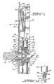
- the actuator assembly mechanism includes a clutch mechanism, illustrated generally at 1, and means, illustrated generally at 3, for preventing or permitting a rotation transmitting connection of the clutch mechanism.
- the actuator assembly mechanism is housed in a housing 5, mounted on the front (outside) of a door and having an opening 7 therethrough at the front end of the assembly.
- a shaft receiving member 13 is disposed at the output side of the clutch mechanism.
- the clutch mechanism is housed in a clutch cover 15.
- the clutch member includes an input disc 17, which is connected to the input connecting member 11, for rotation therewith, and an output disc 19, which is connected to the shaft receiving member 13 for rotation therewith.
- the shaft receiving member 13 receives a drive shaft 14.
- the connecting member 11 is connected to hub 9 for rotation therewith so that the input disc 17 rotates with the rotation of hub 9.
- the facing surfaces of both the input and output discs include diametrically opposed abutments 21 having bevelled surfaces 23 at their terminating edges.
- the abutments are disposed on, and rise above, a lower surface 24 and are preferably formed integrally with the lower surface.
- Closing slot means comprising, for example, a slot 27 is disposed on the upper peripheral surface of the output disc 19 as can also be seen in Figures 1 and 2.
- the clutch mechanism operates in a manner known in the art, namely, with the spring 25 urging the output disc against the input disc, and with the abutments of the input disc being arranged to be located on the lower surfaces of the output disc, and vice-versa, when the input disc is rotated, the output disc will also rotate.
- the output disc is held against rotation, for example, by applying the fixed means in the closing slot 27 thereof, rotation of the output disc will not be possible even when the input disc is rotated, whereby to prevent a rotation transmitting connection of the clutch.
- the bevelled surfaces of the input disc will cam with the bevelled surfaces of the output disc to push the output disc rearwardly against the force of spring 25.
- the rotation of the input disc will still be possible, however, the rotation of the input disc will, in this condition, not be transmitted to the output disc.
- means for permitting a rotation transmitting connection of the clutch comprises a means for removing the fixed means from the closing slot 27.
- the means for permitting a rotation transmitting connection of the clutch is illustrated generally at 3 and comprises a solenoid 29 (see Figures 1, 2 and 7) mounted on a solenoid mounting plate 31. Extending downwardly from the solenoid is a solenoid shaft 33 which is attached to a limiting disc 35 at the bottom end thereof, and whose top end abuts spring member 30.
- a blocking pin 37 Extending downwardly and centrally of the limiting disc 35 is a blocking pin 37. As can be seen in Figures 1 and 2, the blocking pin 37 will extend into the slot 27 when the assembly is in its rest condition. With the blocking pin in the slot 27, the output disc is held against rotation, so that rotation of the input disc will not be transmitted to the output disc.
- the solenoid is contained in a solenoid housing 39, and the blocking pin 37 extends through a wear-resistant reinforcement bushing 41 in the housing 39.
- the wear-resistant bushing accurately guides the travel of the pin 37 and prevents wear resulting from such travel, and provides protection against material deformation from lateral forces of the pin.
- the clutch mechanism and means for effecting rotation transmitting connection are mounted on a mounting plate 43.
- Means for detecting handle rotation is illustrated generally at 45 in Figures 1 and 5 and includes a stop plate 47.
- one end 60 of the stop plate 47 abuts against a switch arrangement 49.
- a retaining ring 51 is provided to prevent hub 9 from sliding out of the housing 5.
- a spring means 53 has one end connected to a fixed point 55 on casing 5 and the other end connected to point 57 on the stop plate.
- Stop plate limiter 59 which is part of casing 5, limits the rotary motion of the stop plate and thereby the rotary motion of the hub 9.
- the hub 9 is rotated in a clockwise direction ( Figure 5) and the stop plate 47 is rotated with it.
- the spring means 53 will cause the stop plate 47 to rotate in a counter-clockwise direction ( Figure 5) until the edge 60 of the stop plate abuts against the stop-plate limiter 59 and thereby against switch arrangement 49.
- switch 49 is of that kind which is closed in its normal condition, i.e., it must be pressed to be opened.
- stop plate 47 With stop plate 47 in its rest condition, as illustrated in Figure 5, end 60 of the stop plate is pressed up against the switch 49 so that the switch 49 is open.
- switch 49 will change state, i.e., it will assume its normal condition and will therefore be closed, i.e., the circuit of which it is a part will be complete. This circuit will then provide a signal that the handle has been rotated.
- plate 47 will return to the position shown in Figure 5, that is, with the end 60 of plate 47 abutting against the switch 49, and the switch 49 will again be open.
- the hub 9 is connected to, for example, a door knob lever handle or the like for rotation, and the shaft 14 can comprise the shaft of, for example, a latch mechanism or the like to retract the latch of a lock as is well known in the art. It will be seen that the assembly is automatically returned to the rest condition from the actuated condition either after a single opening or after a predetermined time delay.
- the mechanism is under the control of an electronic processor which receives data both from the card reader and from the switch 49.
- the processor will have several other functions, we will consider here only its operation in providing power to the solenoid at the appropriate time.
- FIG 6 illustrates an operational flow chart of the software which drives the processor.
- Each cycle of the processor starts, as is well known, with a BEGIN step.
- the BEGIN step in this case would be actuated by the insertion of a coded card into the card reader arrangement, which insertion is sensed by a card-in sensor means 90 (see Figure 1), i.e., a switch which is tripped by the card as it is ! being inserted.
- the tripping of the switch activates both the microprocessor and the reader, which would be normally unactivated, for their respective functions.
- the sensor means 19 also senses when the card is removed from the slot whereby to ensure that the card is not accidentally left in the slot after the door is opened. ;
- the processor would then read the code on the card and determine whether or not this is a valid code. If it is not a valid code, then the program skips to the END, thus avoiding actuation of the assembly, and is ready for the beginning of a new cycle.
- the processor initiates a security timing period.
- the switch 49 is checked to determine whether the handle is in the rest position. If it is not, then the program will skip to the END thus prohibiting the actuation of the assembly.
- an indicator such as indicator 79 in Figure 8 is turned on indicating to the user that he can now rotate the handle.
- the processor now senses alternatively in cycles two conditions, namely, whether the security timing period has elapsed and whether the handle has been rotated. If, in any one of the cycles, the security timing period has not elapsed, and the handle has been rotated, then the solenoid is activated for a predetermined period, e.g., 1/3 sec. The cycle is then completed and the processor is ready to begin a new cycle.
- FIG 6A is a purely schematic illustration of the physical process which takes place.
- the electronic processor receives input from switch 49, card-in sensor 90, and the card reader magnetic head 89 (see Figure 1). It provides an output to the power supply to provide power to activate the solenoid under the appropriate conditions.
- override mechanism illustrated generally at 61 in Figures 2 and 7 is provided.
- the override mechanism comprises a cylindrical core 63.
- a cylindrical core adapter 65 and a cylindrical core extension member 67 connected to the adapter 65 whereby the extension 67 will rotate with the cylindrical core 63.
- the adapter 65 and the extension 67 are required only when the override mechanism must extend for a distance greater than the distance of the core 63 itself.
- an override cam member 69 Disposed at the free end of the extension 67 is an override cam member 69. Extending into the solenoid housing at right angles to the extension member 67 is an override plunger 71.
- the plunger 71 has a camming end 73 and a disc end 75.
- Spring means 77 has one end thereof abutting against the disc end 75 and the other end abutting against stopping edge of the solenoid housing.
- the housing for the mechanism is shown to include the casing 5 and a handle 6 which is connected with the hub 9 as is well known.
- the card reader assembly illustrated generally at 81, includes a slot 83 for receiving a card 85.
- the card reader arrangement also includes a window 87 which is in communication with the slot 83.
- the inclusion of the window permits a user to see that the card has been inserted as far as it should go. It also makes it easy and convenient to clean the arrangement and especially to dislodge any foreign objects which might get stuck in the slot.
- the card reader assembly also includes a magnetic head 89 for reading the code on the card as is also well known in the art, and a card-in sensor means 90.
- the sensor means 90 is located so that the card activates the sensor 90 before or at the same time that it reaches the head 89.
- the magnetic head is mounted on a spring 91 which biases it in the direction of the card so that there will be good physical contact between the magnetic head and the coded portion of the card.
- a coded card is inserted in the slot and the code on the card is read by the magnetic head and provided to the processor as illustrated schematically in Figure 6A.
- FIG. 9 illustrates a security arrangement for mounting such a handle.
- the rear door handle is mounted adjacent the rear (inside) surface 93 of the door. It includes a spring-loaded square shaft 95, a stop plate 97, a return spring 98 and a rosette 99.
- the rosette, stop plate and return spring are provided so that handles of the type illustrated in Figure 8 will, upon release, move to their rest (horizontal) position.
- a flange 100 Mounted on the shaft 95 is a flange 100 with a floating collar 101 which has external threads 103.
- the floating collar, rosette and shaft 95 arrangement are encased by casing 105.
- the handle 107 has internal threads 109 which mate with the external threads 103 whereby to mount the handle on the floating collar.
- a portion 111 of the floating collar 101 which is formed integrally with the floating collar, has its outer periphery notched with equally spaced notches.
- the floating collar can be rotated about the axle 95 as will be further discussed below.
- Plastic bearing 117 is provided between the flange 100 and the central opening of the rosette to ease movement of the flange 100 relative to the rosette.
- the shaft 95 is square in cross-section, and the handle includes an opening 119 which has a cross-sectional shape similar to the cross-sectional shape of the floating shaft. Because both cross-sectional shapes are discontinuous, when the handle 107 is rotated, the shaft 95 will rotate with it.
- Pin 121 extends from opposing sides of the shaft 95 to prevent the shaft 95 from falling out of the flange 100.
- slots 123 are formed on either side of the opening to accomodate both ends of the pin 121.
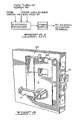
- the casing 105 includes a cavity 127, which is mounted in recess 128 in the door, with a cover plate 129. An opening 131 is included in the cavity.
- the plate 129 is mounted on the casing by inserting one end thereof into the slotted opening 133.
- a post 135 is mounted on a surface of the indented portion.
- a hook member 137 engages the post 135 to lock the cover plate 129 onto the casing when the hook member is rotated by a key which is received in a key receptacle 139.
- the assembly including the rosette, the floating collar, flange, stop plate, return spring, and the shaft is mounted on the door.
- the casing 105 is placed on the door, and then the handle is placed over the floating collar so that teeth 109 are close to teeth 103.
- tool 113 is inserted through opening 131 to engage the notches on portion 111 of floating collar 101.
- the tool is rotated to thereby rotate the floating collar so that the screw threads 103 will mesh with and engage screw threads 109. This is continued until the floating collar can no longer be rotated, i.e., the handle is fully mounted on the floating collar.
- the shaft 95 will, of course, extend into the opening 119.
- the cover plate 129 is then placed in position with one end in the slotted opening 133, and the key is inserted in receptacle 139 and rotated so that the hook 137 will engage the post 135. With the cover plate 129 in its mounted position, the handle can no longer be removed from the collar as access to opening 131 is blocked by the cover plate 129.
- cover plate 129 is removed by first rotating the key in receptacle 139 so that the hook 137 no longer engages the post 135. The other end is then removed from the slotted opening 133 so that there is once again access to the opening 131. The tool is inserted through the opening, and the floating collar is rotated to unscrew the collar from the handle.
- C-clip 140 is provided to hold together the assembly of the flange, floating collar, stop plate, the return spring and the rosette.
- the opening in the cavity 127 can be used to store batteries to provide power to the actuating assembly and the processor.
- FIG. 11 An alternate arrangement is illustrated in Figure 11.
- the embodiment illustrated in Figure 11 also includes a casing 105.
- the casing 105 of the Figure 11 embodiment includes a cavity 127 having an opening 131. Access to the opening can be prevented by also providing a cover plate 129.
- the Figure 11 embodiment also includes a spring-loaded shaft 195 which is square in its cross-sectional shape, and the shaft is inserted in a square opening in the handle 207 so that the shaft will rotate with the handle.
- Spring 225 maintains the shaft in its fully extended position as shown in Figure 11.
- the member 201 in the Figure 11 embodiment is not a floating collar but is, rather, formed integrally with the handle 207.
- Collar 203 formed integrally with rosette 199 embraces the member 201, and plastic bearings 209 and 211 ease the movement of the member 201 relative to the collar 203.
- C-clip 205 which abuts against the bottom surface of the collar 203, maintains the handle fixed in position as shown in Figure 11.
- the C-clip can be mounted onto the member 201 by a special tool through the opening 131 in the casing, and an aligned opening in the rosette (not shown), and the C-clip can also be removed from its position by use of a suitable, but different, tool through the same opening. Accordingly, once again, it would be necessary to remove the cover plate 129, using a key, before the handle 207 can be removed.
- Posts 213 extend through an opening in the lock set and mate with screws 215 which are inserted through an outer surface of the front of the door.
Landscapes
- Physics & Mathematics (AREA)
- General Physics & Mathematics (AREA)
- Lock And Its Accessories (AREA)
- Conveying Record Carriers (AREA)
- Mechanical Control Devices (AREA)
- Sheets, Magazines, And Separation Thereof (AREA)
Priority Applications (1)
| Application Number | Priority Date | Filing Date | Title |
|---|---|---|---|
| AT86112892T ATE76474T1 (de) | 1985-09-24 | 1986-09-18 | Schlossbetaetigungsvorrichtung und leseeinrichtung fuer information tragende karte. |
Applications Claiming Priority (2)
| Application Number | Priority Date | Filing Date | Title |
|---|---|---|---|
| US06/779,455 US4762212A (en) | 1985-09-24 | 1985-09-24 | Lock actuator assembly and card reader |
| US779455 | 1985-09-24 |
Publications (3)
| Publication Number | Publication Date |
|---|---|
| EP0219694A2 true EP0219694A2 (de) | 1987-04-29 |
| EP0219694A3 EP0219694A3 (en) | 1988-07-27 |
| EP0219694B1 EP0219694B1 (de) | 1992-05-20 |
Family
ID=25116505
Family Applications (1)
| Application Number | Title | Priority Date | Filing Date |
|---|---|---|---|
| EP19860112892 Expired - Lifetime EP0219694B1 (de) | 1985-09-24 | 1986-09-18 | Schlossbetätigungsvorrichtung und Leseeinrichtung für Information tragende Karte |
Country Status (9)
| Country | Link |
|---|---|
| US (1) | US4762212A (de) |
| EP (1) | EP0219694B1 (de) |
| JP (1) | JP2552459B2 (de) |
| AT (1) | ATE76474T1 (de) |
| AU (1) | AU596373B2 (de) |
| CA (2) | CA1260727A (de) |
| DE (1) | DE3685398D1 (de) |
| IL (1) | IL80012A0 (de) |
| ZA (1) | ZA866932B (de) |
Cited By (7)
| Publication number | Priority date | Publication date | Assignee | Title |
|---|---|---|---|---|
| EP0452832A2 (de) * | 1990-04-18 | 1991-10-23 | Mauer GmbH | Elektrisch ansteuerbares Türschloss |
| FR2682985A1 (fr) * | 1991-10-28 | 1993-04-30 | Jpm Chauvat Sa | Boitier reversible pour la commande et la condamnation d'une serrure antipanique a barre de poussee. |
| EP0785324A1 (de) * | 1996-01-17 | 1997-07-23 | KARL FLIETHER GmbH & Co. | Antriebsvorrichtung für ein Schloss, einen Schliesszylinder oder dergleichen |
| WO1998002630A1 (en) * | 1996-07-16 | 1998-01-22 | Schlage Lock Company | Lockset with motorized system for locking and unlocking |
| EP0947647A1 (de) * | 1998-03-31 | 1999-10-06 | IKON AKTIENGESELLSCHAFT Präzisionstechnik | Sicherheitsschloss für die Tür eines Gehäuses |
| WO2010046677A1 (en) * | 2008-10-20 | 2010-04-29 | Genesis Properties (Scotland) Limited | Door or window security system for mounting at a door or window frame |
| WO2010140949A1 (en) * | 2009-06-01 | 2010-12-09 | Xitena Security Ab | A connecting device at a turning axle of a lockable unit |
Families Citing this family (16)
| Publication number | Priority date | Publication date | Assignee | Title |
|---|---|---|---|---|
| US4916299A (en) * | 1985-09-24 | 1990-04-10 | Ilco Unican Inc. | Card recepticle housing |
| US4854143A (en) * | 1987-08-07 | 1989-08-08 | Intelock Corporation | Bolt assembly and method |
| JPH0823878B2 (ja) * | 1988-04-21 | 1996-03-06 | 沖電気工業株式会社 | カード書込み・読出し装置 |
| GB8827906D0 (en) * | 1988-11-30 | 1989-01-05 | Yale Security Prod Ltd | Electromagnetically activated mechanisms |
| US4941697A (en) * | 1989-11-28 | 1990-07-17 | Caesar Fan | Over-loading idling lock set |
| US5819563A (en) * | 1991-10-21 | 1998-10-13 | Bianco; James S. | Intelligent lock system |
| US5487289A (en) * | 1993-06-23 | 1996-01-30 | Herman Miller, Inc. | Lock assembly |
| GB2287981B (en) | 1994-03-30 | 1997-07-16 | Klaus Wilhelm Gartner | Electronic input and dial entry lock |
| US5845523A (en) * | 1994-03-30 | 1998-12-08 | U-Code, Inc. | Electronic input and dial entry lock |
| US5887467A (en) * | 1994-03-30 | 1999-03-30 | U-Code, Inc. | Pawl & solenoid locking mechanism |
| NO313761B1 (no) * | 1996-06-13 | 2002-11-25 | Vingcard As | Anordning ved lås, spesielt en elektromagnetisk låseenhet |
| DE19707762C1 (de) * | 1997-02-26 | 1998-04-16 | Fuss Fritz Gmbh & Co | Sicherheitsschloß |
| US5867107A (en) * | 1997-06-03 | 1999-02-02 | Masco Corporation | Variation coded electro-mechanical lock and method of using same |
| US7963134B2 (en) * | 2003-08-20 | 2011-06-21 | Master Lock Company Llc | Deadbolt lock |
| US8677792B2 (en) * | 2009-02-25 | 2014-03-25 | Adams Rite Manufacturing Co. | Electronic door lock apparatus |
| DE202013101990U1 (de) * | 2013-05-08 | 2013-06-19 | Goetz-Bolko Holz | Elektronische Schließvorrichtung |
Citations (2)
| Publication number | Priority date | Publication date | Assignee | Title |
|---|---|---|---|---|
| US593833A (en) | 1897-11-16 | Washing-machine | ||
| US4488036A (en) | 1982-09-23 | 1984-12-11 | Scovill Inc. | Keycard reader |
Family Cites Families (10)
| Publication number | Priority date | Publication date | Assignee | Title |
|---|---|---|---|---|
| US2226917A (en) * | 1939-08-03 | 1940-12-31 | Rudolph E Zeruneith | Safety control |
| US2910859A (en) * | 1954-09-23 | 1959-11-03 | Harry W Allen | Anti-jimmy lock |
| US3677043A (en) * | 1970-12-07 | 1972-07-18 | Clifford B Cox | Remote control door lock |
| GB1452032A (en) * | 1974-01-04 | 1976-10-06 | Goal Kk | Locks |
| US4177657A (en) * | 1976-04-16 | 1979-12-11 | Kadex, Inc. | Electronic lock system |
| JPS5578772A (en) * | 1978-12-09 | 1980-06-13 | Kadetsukusu Inc | Electronic locking apparatus |
| DE3034606A1 (de) * | 1980-09-13 | 1982-03-25 | Jean Walterscheid Gmbh, 5204 Lohmar | Schaltvorrichtung fuer eine ueberlastkupplung |
| JPS57125043A (en) * | 1981-01-26 | 1982-08-04 | Dainippon Printing Co Ltd | Grain decorative wood |
| US4394821A (en) * | 1981-06-05 | 1983-07-26 | Best Lock Corporation | Door lock mechanism |
| US4592453A (en) * | 1984-03-27 | 1986-06-03 | Ilco Unican Inc. | Lock actuator assembly |
-
1985
- 1985-09-24 US US06/779,455 patent/US4762212A/en not_active Expired - Lifetime
- 1985-11-26 CA CA000496229A patent/CA1260727A/en not_active Expired
-
1986
- 1986-09-11 ZA ZA866932A patent/ZA866932B/xx unknown
- 1986-09-11 IL IL80012A patent/IL80012A0/xx not_active IP Right Cessation
- 1986-09-17 AU AU62976/86A patent/AU596373B2/en not_active Ceased
- 1986-09-18 AT AT86112892T patent/ATE76474T1/de active
- 1986-09-18 DE DE8686112892T patent/DE3685398D1/de not_active Expired - Fee Related
- 1986-09-18 EP EP19860112892 patent/EP0219694B1/de not_active Expired - Lifetime
- 1986-09-24 JP JP22574586A patent/JP2552459B2/ja not_active Expired - Lifetime
-
1988
- 1988-04-12 CA CA000563961A patent/CA1257104A/en not_active Expired
Patent Citations (2)
| Publication number | Priority date | Publication date | Assignee | Title |
|---|---|---|---|---|
| US593833A (en) | 1897-11-16 | Washing-machine | ||
| US4488036A (en) | 1982-09-23 | 1984-12-11 | Scovill Inc. | Keycard reader |
Cited By (10)
| Publication number | Priority date | Publication date | Assignee | Title |
|---|---|---|---|---|
| EP0452832A2 (de) * | 1990-04-18 | 1991-10-23 | Mauer GmbH | Elektrisch ansteuerbares Türschloss |
| EP0452832A3 (en) * | 1990-04-18 | 1991-12-18 | Mauer Gmbh | Electrically controlled door lock |
| FR2682985A1 (fr) * | 1991-10-28 | 1993-04-30 | Jpm Chauvat Sa | Boitier reversible pour la commande et la condamnation d'une serrure antipanique a barre de poussee. |
| EP0785324A1 (de) * | 1996-01-17 | 1997-07-23 | KARL FLIETHER GmbH & Co. | Antriebsvorrichtung für ein Schloss, einen Schliesszylinder oder dergleichen |
| WO1998002630A1 (en) * | 1996-07-16 | 1998-01-22 | Schlage Lock Company | Lockset with motorized system for locking and unlocking |
| US5782118A (en) * | 1996-07-16 | 1998-07-21 | Schlage Lock Company | Lockset with motorized system for locking and unlocking |
| US6038896A (en) * | 1996-07-16 | 2000-03-21 | Schlage Lock Company | Lockset with motorized system for locking and unlocking |
| EP0947647A1 (de) * | 1998-03-31 | 1999-10-06 | IKON AKTIENGESELLSCHAFT Präzisionstechnik | Sicherheitsschloss für die Tür eines Gehäuses |
| WO2010046677A1 (en) * | 2008-10-20 | 2010-04-29 | Genesis Properties (Scotland) Limited | Door or window security system for mounting at a door or window frame |
| WO2010140949A1 (en) * | 2009-06-01 | 2010-12-09 | Xitena Security Ab | A connecting device at a turning axle of a lockable unit |
Also Published As
| Publication number | Publication date |
|---|---|
| JPS62110669A (ja) | 1987-05-21 |
| US4762212A (en) | 1988-08-09 |
| AU6297686A (en) | 1987-03-26 |
| ATE76474T1 (de) | 1992-06-15 |
| EP0219694B1 (de) | 1992-05-20 |
| ZA866932B (en) | 1987-04-29 |
| AU596373B2 (en) | 1990-05-03 |
| EP0219694A3 (en) | 1988-07-27 |
| IL80012A0 (en) | 1986-12-31 |
| JP2552459B2 (ja) | 1996-11-13 |
| CA1260727A (en) | 1989-09-26 |
| CA1257104A (en) | 1989-07-11 |
| DE3685398D1 (de) | 1992-06-25 |
Similar Documents
| Publication | Publication Date | Title |
|---|---|---|
| US4762212A (en) | Lock actuator assembly and card reader | |
| EP1049843B1 (de) | Kombinationsschloss mit riegel und zug-druck-schloss, beide mit integrierten doppel-schliessmerkmalen, schloss mit zusätzlichen sicherheitsmerkmalen und tastenfeld für schloss mit merkmalen zur erkennung von und reaktion auf unbefugte manipulation | |
| US5862692A (en) | Safe door lock with servo motor operated cam | |
| US5887467A (en) | Pawl & solenoid locking mechanism | |
| US20020056300A1 (en) | Electromechanical lock | |
| US5791177A (en) | Compact electronic lock | |
| EP0247062B1 (de) | Sicherheitsanordnung, insbesondere elektrisch betätigtes schloss | |
| US4656850A (en) | Electric lock | |
| US6483424B1 (en) | Electronic lock and key apparatus and method | |
| US20060283219A1 (en) | Device at lock | |
| EP0392596B1 (de) | Schloss mit elektromechanischem Entriegelungsmechanismus | |
| WO2003058012A2 (en) | Swing bolt lock with improved tamper resistance and method of operation | |
| WO2010088799A1 (zh) | 自复位且电源来自钥匙的智能旋转锁芯及配套锁具和钥匙 | |
| US4916299A (en) | Card recepticle housing | |
| CN1032210A (zh) | 多功能电子锁的闩锁机构 | |
| GB2437651A (en) | Access control means with biometric sensor | |
| US4861083A (en) | Lock actuator assembly and card reader | |
| WO2004070143A1 (en) | Lock cylinder with key | |
| WO1985003971A1 (en) | Checking devices for fasteners | |
| CA1263037A (en) | Lock actuator assembly and card reader | |
| KR100535243B1 (ko) | 도어 잠금장치 | |
| EP0248095B1 (de) | Schlossbetätigungsvorrichtung | |
| GB2297354A (en) | An electronic combination lock having a dial-shaped handle with a keypad | |
| GB2189860A (en) | Clutch mechanism | |
| JPH0534035B2 (de) |
Legal Events
| Date | Code | Title | Description |
|---|---|---|---|
| PUAI | Public reference made under article 153(3) epc to a published international application that has entered the european phase |
Free format text: ORIGINAL CODE: 0009012 |
|
| AK | Designated contracting states |
Kind code of ref document: A2 Designated state(s): AT BE CH DE FR GB IT LI LU NL SE |
|
| PUAL | Search report despatched |
Free format text: ORIGINAL CODE: 0009013 |
|
| 17P | Request for examination filed |
Effective date: 19880422 |
|
| AK | Designated contracting states |
Kind code of ref document: A3 Designated state(s): AT BE CH DE FR GB IT LI LU NL SE |
|
| 17Q | First examination report despatched |
Effective date: 19891013 |
|
| GRAA | (expected) grant |
Free format text: ORIGINAL CODE: 0009210 |
|
| ITF | It: translation for a ep patent filed | ||
| AK | Designated contracting states |
Kind code of ref document: B1 Designated state(s): AT BE CH DE FR GB IT LI LU NL SE |
|
| PG25 | Lapsed in a contracting state [announced via postgrant information from national office to epo] |
Ref country code: SE Effective date: 19920520 Ref country code: NL Effective date: 19920520 Ref country code: LI Effective date: 19920520 Ref country code: CH Effective date: 19920520 Ref country code: BE Effective date: 19920520 Ref country code: AT Effective date: 19920520 |
|
| REF | Corresponds to: |
Ref document number: 76474 Country of ref document: AT Date of ref document: 19920615 Kind code of ref document: T |
|
| REF | Corresponds to: |
Ref document number: 3685398 Country of ref document: DE Date of ref document: 19920625 |
|
| ET | Fr: translation filed | ||
| REG | Reference to a national code |
Ref country code: CH Ref legal event code: PL |
|
| PG25 | Lapsed in a contracting state [announced via postgrant information from national office to epo] |
Ref country code: LU Free format text: LAPSE BECAUSE OF NON-PAYMENT OF DUE FEES Effective date: 19920930 |
|
| NLV1 | Nl: lapsed or annulled due to failure to fulfill the requirements of art. 29p and 29m of the patents act | ||
| PLBE | No opposition filed within time limit |
Free format text: ORIGINAL CODE: 0009261 |
|
| STAA | Information on the status of an ep patent application or granted ep patent |
Free format text: STATUS: NO OPPOSITION FILED WITHIN TIME LIMIT |
|
| 26N | No opposition filed | ||
| PGFP | Annual fee paid to national office [announced via postgrant information from national office to epo] |
Ref country code: FR Payment date: 19960828 Year of fee payment: 11 |
|
| PGFP | Annual fee paid to national office [announced via postgrant information from national office to epo] |
Ref country code: DE Payment date: 19960930 Year of fee payment: 11 |
|
| PGFP | Annual fee paid to national office [announced via postgrant information from national office to epo] |
Ref country code: GB Payment date: 19970904 Year of fee payment: 12 |
|
| PG25 | Lapsed in a contracting state [announced via postgrant information from national office to epo] |
Ref country code: FR Free format text: THE PATENT HAS BEEN ANNULLED BY A DECISION OF A NATIONAL AUTHORITY Effective date: 19970930 |
|
| PG25 | Lapsed in a contracting state [announced via postgrant information from national office to epo] |
Ref country code: DE Free format text: LAPSE BECAUSE OF NON-PAYMENT OF DUE FEES Effective date: 19980603 |
|
| REG | Reference to a national code |
Ref country code: FR Ref legal event code: ST |
|
| PG25 | Lapsed in a contracting state [announced via postgrant information from national office to epo] |
Ref country code: GB Free format text: LAPSE BECAUSE OF NON-PAYMENT OF DUE FEES Effective date: 19980918 |
|
| GBPC | Gb: european patent ceased through non-payment of renewal fee |
Effective date: 19980918 |
|
| PG25 | Lapsed in a contracting state [announced via postgrant information from national office to epo] |
Ref country code: IT Free format text: LAPSE BECAUSE OF NON-PAYMENT OF DUE FEES;WARNING: LAPSES OF ITALIAN PATENTS WITH EFFECTIVE DATE BEFORE 2007 MAY HAVE OCCURRED AT ANY TIME BEFORE 2007. THE CORRECT EFFECTIVE DATE MAY BE DIFFERENT FROM THE ONE RECORDED. Effective date: 20050918 |