EP0248095B1 - Schlossbetätigungsvorrichtung - Google Patents
Schlossbetätigungsvorrichtung Download PDFInfo
- Publication number
- EP0248095B1 EP0248095B1 EP86107344A EP86107344A EP0248095B1 EP 0248095 B1 EP0248095 B1 EP 0248095B1 EP 86107344 A EP86107344 A EP 86107344A EP 86107344 A EP86107344 A EP 86107344A EP 0248095 B1 EP0248095 B1 EP 0248095B1
- Authority
- EP
- European Patent Office
- Prior art keywords
- assembly
- condition
- fork
- pivoting
- disc
- Prior art date
- Legal status (The legal status is an assumption and is not a legal conclusion. Google has not performed a legal analysis and makes no representation as to the accuracy of the status listed.)
- Expired - Lifetime
Links
Images


Classifications
-
- E—FIXED CONSTRUCTIONS
- E05—LOCKS; KEYS; WINDOW OR DOOR FITTINGS; SAFES
- E05B—LOCKS; ACCESSORIES THEREFOR; HANDCUFFS
- E05B47/00—Operating or controlling locks or other fastening devices by electric or magnetic means
- E05B47/0001—Operating or controlling locks or other fastening devices by electric or magnetic means with electric actuators; Constructional features thereof
- E05B47/0012—Operating or controlling locks or other fastening devices by electric or magnetic means with electric actuators; Constructional features thereof with rotary electromotors
-
- E—FIXED CONSTRUCTIONS
- E05—LOCKS; KEYS; WINDOW OR DOOR FITTINGS; SAFES
- E05B—LOCKS; ACCESSORIES THEREFOR; HANDCUFFS
- E05B13/00—Devices preventing the key or the handle or both from being used
- E05B13/002—Devices preventing the key or the handle or both from being used locking the handle
- E05B13/004—Devices preventing the key or the handle or both from being used locking the handle by locking the spindle, follower, or the like
-
- E—FIXED CONSTRUCTIONS
- E05—LOCKS; KEYS; WINDOW OR DOOR FITTINGS; SAFES
- E05B—LOCKS; ACCESSORIES THEREFOR; HANDCUFFS
- E05B17/00—Accessories in connection with locks
- E05B17/0054—Fraction or shear lines; Slip-clutches, resilient parts or the like for preventing damage when forced or slammed
- E05B17/0058—Fraction or shear lines; Slip-clutches, resilient parts or the like for preventing damage when forced or slammed with non-destructive disengagement
-
- E—FIXED CONSTRUCTIONS
- E05—LOCKS; KEYS; WINDOW OR DOOR FITTINGS; SAFES
- E05B—LOCKS; ACCESSORIES THEREFOR; HANDCUFFS
- E05B47/00—Operating or controlling locks or other fastening devices by electric or magnetic means
- E05B47/0001—Operating or controlling locks or other fastening devices by electric or magnetic means with electric actuators; Constructional features thereof
- E05B2047/0014—Constructional features of actuators or power transmissions therefor
- E05B2047/0018—Details of actuator transmissions
- E05B2047/0024—Cams
-
- E—FIXED CONSTRUCTIONS
- E05—LOCKS; KEYS; WINDOW OR DOOR FITTINGS; SAFES
- E05B—LOCKS; ACCESSORIES THEREFOR; HANDCUFFS
- E05B47/00—Operating or controlling locks or other fastening devices by electric or magnetic means
- E05B47/0001—Operating or controlling locks or other fastening devices by electric or magnetic means with electric actuators; Constructional features thereof
- E05B2047/0014—Constructional features of actuators or power transmissions therefor
- E05B2047/0018—Details of actuator transmissions
- E05B2047/0026—Clutches, couplings or braking arrangements
-
- E—FIXED CONSTRUCTIONS
- E05—LOCKS; KEYS; WINDOW OR DOOR FITTINGS; SAFES
- E05B—LOCKS; ACCESSORIES THEREFOR; HANDCUFFS
- E05B43/00—Time locks
-
- Y—GENERAL TAGGING OF NEW TECHNOLOGICAL DEVELOPMENTS; GENERAL TAGGING OF CROSS-SECTIONAL TECHNOLOGIES SPANNING OVER SEVERAL SECTIONS OF THE IPC; TECHNICAL SUBJECTS COVERED BY FORMER USPC CROSS-REFERENCE ART COLLECTIONS [XRACs] AND DIGESTS
- Y10—TECHNICAL SUBJECTS COVERED BY FORMER USPC
- Y10T—TECHNICAL SUBJECTS COVERED BY FORMER US CLASSIFICATION
- Y10T70/00—Locks
- Y10T70/70—Operating mechanism
- Y10T70/7006—Predetermined time interval controlled
- Y10T70/7011—Positively initiated delay interval
- Y10T70/7017—Interval terminating
Definitions
- the invention relates to a lock actuator assembly which includes a clutch mechanism having an input disc and an output disc. More specifically, the invention relates to such an assembly wherein the output disc can only be rotated once, when the assembly is actuated, within a given time delay, and wherein the second disc is not rotatable if the first disc is not rotated within the time delay.
- actuator assemblies for door locking mechanisms. Most of these actuator assemblies will remain open until such time as the door is opened once they have been actuated. Thus, if the assembly is actuated and the person actuating the assembly decides to leave and not open the door, the door is left open for possible unauthorized entry.
- actuator assemblies known in the art are subject to break-ins by mechanical picks or the like.
- a lock is known from Canadian patent n o 967 614 (KELLER) wherein the bolt is under the control of a timer unit incorporated in the lock.
- the timer unit is manually activated with a key and comprises a standard clock, a delay timing cam, a relocking timing cam and a cylinder cam which in combination provide an open cycle during which the bolt can be retracted by the rotation of a key.
- an open cycle timing cam is provided in association with electrical means to control the duration of the open cycle.
- Such an arrangment is a lock by itself and does not constitute an actuator assembly for a lock. In other words, it cannot be adapted to already existing lock. Also in the event of failure or for maintenance, dismounting of such an arrangement lets the door without closing means during the repairs. Moreover, the timer mechanism is manually activated with a key. Therefore, it cannot be used with numeral combination means which are more and more used nowadays. It is also to be noted that the lock can be opened several time during the open cycle so that if this latter is long enough, the door is left open for an unauthorized entry. Finally, an arrangement comprising such a number of cams to assemble and to set must certainly be difficult and costly to produce.
- a lock actuator assembly electrically activated and having a time delay action which overcomes all of the above disadvantages, comprising a clutch mechanism having an input disc and an output disc to be connected to an input shaft of a lock; means for rotating the input disc; means provided for preventing rotation of the output disc with the input disc when the assembly is in a rest condition, and for effecting a rotation transmitting connection between the input disc and the output disc when the assembly is in an actuated condition. Means are also provided for automatically returning the assembly from the actuated condition to the rest condition: (1) if the input disc is rotated within a given time delay, upon the rotation; or, (2) if the input disc is not rotated within the given time delay, upon the expiration of the time delay.
- the output disc can be rotated only once within the time delay, and the output disc is not rotatable at all if the input disc is not rotated within the time delay.
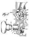
- the actuator includes a clutch mechanism, illustrated generally at 1, and means illustrated generally at 3 for effecting a rotation transmitting connection of the clutch mechanism.
- the actuator is housed in a casing 5 having an opening 7 therethrough at the front of the actuator.
- a knob sleeve 9, which is spring loaded, by means not shown, to return to its initial position extends through the opening and is in rotation transmitting communication with a connecting member 11 at the input of the clutch.
- a shaft receiving member 13 is disposed at the output side of the clutch.
- the clutch is housed in a clutch housing 15.
- the clutch member includes an input disc 17, which is connected to the input connecting member 11, for rotation therewith and an output disc 19, which is connected to the shaft receiving member 13 for rotation therewith.
- the connecting member 11 is connected to knob sleeve 9 for rotation therewith so that input disc 17 rotates with the rotation of knob sleeve 9.
- the facing surfaces of both the input and output discs includes diametrically opposed abutments 21 having bevelled surfaces 23 at their terminating edges.
- the abutments are disposed on a lower surface 24 and are preferably formed integrally with the lower surface.
- Closing slot means comprising, for example, slots 27 are disposed on diametrically opposed peripheral surfaces of the output disc 19, and the closing slots are in alignment with openings 28 of the cover 15. The openings 28 overlie the slots 27.
- the clutch mechanism operates in a manner well known in the art, namely, with the spring 25 urging the output disc against the input disc, and with the abutments of the input disc being arranged to be located on the lower surfaces of the output disc, and vice-versa, when the input disc is rotated, the output disc will also rotate.
- the output disc is held against rotation, for example, by applying fixed means in the closing slots 27 thereof, rotation of the output disc will not be possible even when the input disc is rotated. Instead, the bevelled surfaces of the input disc will cam with the bevelled surfaces of the output disc to push the output disc rearwardly against the force of the spring 25.
- the rotation of the input disc will still be possible, however, the rotation of the input disc will, in this condition, not be transmitted to the output disc.
- the means 3 for effecting a rotation transmitting connection of the clutch comprises a pivoting fork 29.
- the pivoting fork is mounted for pivoting about a fixed pivot point 31 and includes locking pins 33 at the lower edges 35 thereof.
- the lower end of the pivoting fork comprises leg means, comprising, for example, legs 37 which straddle the clutch mechanism 1 as best seen in Figure 3.
- the locking pins 33 are located in the closing slots 27 to hold the output disc against rotation.
- the top end of the pivoting fork comprises an abutment end 39 to be discussed below.
- Spring means illustrated diagramatically at 40 in Figures 1 and 2 urge the fork means into its rest condition as shown in Figure 1.
- a locking lever 43 and and a fork holding lever 45 Extending from opening 41 in fork 29 are a locking lever 43 and and a fork holding lever 45.
- the levers 43 and 45 are mounted for pivotal motion on shaft 47 carried by the fork 29.
- a spring means illustrated diagrammatically at 49 in Figure 3, to provide a positive bias of the levers in a downward direction.
- the front end of lever 43 includes a retaining dog 51, and a depending abutment member 53 is provided on the lower edge of lever 45.
- the mounting plate 55 Disposed forward of the pivoting fork 29 is a mounting plate 55 fixed with respect to the casing 5.
- the position of the mounting plate is illustrated in Figures 1 and 2, and the mounting plate is per se illustrated in greater detail in Figure 6.
- the mounting plate includes a bottom opening 57 through which the levers 43 and 45 extend.
- a platform 59 is contructed at the top of the mounting plate and supports a rotating mechanism, such as a motor, 61.
- the mounting plate also includes a top opening 63 in which is mounted a dual function cam member 65.
- the dual function cam member is illustrated in greater detail in Figure 7 and it includes a top surface 67 having abutments 69 mounted on rest surface 70.
- the abutments are formed integrally with the rest surface.
- edges of the abutments are terminated by bevelled surfaces 71 at the attack end thereof.
- an eccentric cam 73 Depending from the bottom surface of the dual function cam member is an eccentric cam 73 having a radially extending arm 74. Extending from the top surface is a motor connecting shaft 75.
- a vertically movable slider member 77 disposed in front of the pivoting fork and behind the support plate.
- the slider member which is illustrated in more detail in Figure 8, includes arms 79 which, as can be seen in Figures 1, 2 and 3, are disposed horizontally over the dual function cam member.
- the arms 79 are connected, by vertically connecting members 81, to a transverse bottom strip 83 to define opening 77A.
- Extending downwardly from the bottom strip is a slider nose 85.
- the nose 85 extends into an indent 87 in the output disc 19.
- the slider nose 85 can extend into the indent 87 because the housing 15 does not cover the top part of the output disc 19.
- the bottom part of the output disc is covered by the rear bottom extension 89 of the housing 15, however, as seen in Figure 4, the top of the output disc 19 remains uncovered.
- the top surface of the bottom strip 83 underlies the bottom surface of the opening 57 in the supporting plate so that, when the slider member moves upwardly, it will contact the levers 43 and 45 and force them in an upward direction against the action of spring 49.
- the actuator assembly works as follows: In the rest condition, as illustrated in Figure 1, the retaining dog 51 on lever 43 overlies the front surface of the bottom edge of opening 57 to thereby restrain pivoting motion of the pivoting fork 29. In addition, the arms 79 of the slider member 77 rest on the rest surface 70 of the dual function cam member. Thus, as seen in Figure 1, the bottom strip 83 of the slider member does not make contact with the levers 43 and 45.
- the lever 45 is maintained in an upward position by contact of the depending member 53 on the bottom edge of the opening 57.
- locking pins 33 are disposed in the closing slots 27 of the output disc of the clutch mechanism, as seen in Figure 3, so that rotation of the input disc, which is transmitted thereto by rotation of the knob sleeve 9, will not be transmitted to the output disc 19.
- the motor is actuated by means, shown diagrammatically at 100 in Figures 1 and 2, which is connected to the motor by means well known in the art but not shown in the drawings.
- the means 100 can comprise a keyed mechanism or an electronic or mechanical numerical combination means or other means well known in the art, and the actuating means will, as well known in the art, provide power to the motor when appropriate action is taken.
- the actuating assembly will remain in its actuated condition until such time as the slider member is once again lifted upwardly. This can be accomplished in one of two ways.
- timing means provides an extra safety feature in accordance with the invention.
- the knob sleeve is connected to, for example, a door knob 10 or the like for rotation, and the shaft receiving member is connected to the shaft of, for example, a latch mechanism or the like to retract the latch as is well known in the art.
- the lock is automatically self-closing either after a single opening or after a predetermined time delay. Accordingly, it is especially advantageous in preventing unauthorized entry.
- the initiation means cam comprise a combination mechanism with changeable combinations.
- lever 43 to restrain the fork 29 from pivoting motion when the assembly is in its rest condition provides an added measure of security in accordance with the invention.
- spring means 40 will urge fork 29 into its rest position to thereby maintain the pins 33 in slots 27, vibrations or jarring forces applied to the mechanisms could overcome the force of the spring to permit the pins to slide out of the slots.
- pins 33 extend from legs 37 into slots 27 on output disc 19, it will be apparent that the pin and slot arrangement could be reversed, i.e., the pins could be on the ouput disc 19 and the slots on the legs 37. Or other means could be used to prohibit the rotation of the output disc when the assembly is in the rest condition. In addition, it is not necessary that there be two legs 37 as a single leg is sufficient.
- timing means As such timing means will readily be constructed from available components by one skilled in the art, it is more instructive to discuss a flow chart illustrating the logic of such a timing means rather than describing a particular circuit. For this purpose, attention is directed to Figure 9.
- the first step is to determine when the actuator assembly is in its actuated condition.
- a sensor for example, a microswitch, illustrated schematically at 1000 in Figures 1 and 2, and mounted on the casing 55 adjacent the dual function cam assembly 65 could be employed.
- the outer peripheral surface of the cam member 65 could press against the microswitch to keep it depressed at all times.
- a notch would be placed on the outer peripheral surface at such a position that the motor should be stopped when the notch is sensed by the microswitch.
- a signal is generated which tells the control circuitry that the assembly is now in its actuated condition. This signal is the control signal for stopping the motor.
- the dual function cam assembly when the assembly is actuated, the dual function cam assembly must be rotated through a large enough angle to raise the sliding member so that it lifts the levers 43 and 45 permitting the pivoting fork 29 to move rearwardly. It must also move through a large enough angle so that the arm 74 will push against the abutment member 39 to force fork 29 rearwardly while levers 43 and 45 are lifted. Finally, it must move through a large enough angle so that the arm 74 will move into a position such that it will not prevent fork 29 from returning to its forward position, i.e., the arm 74 must not be pointing towards the abutment end 39. Thus, in Figure 2 it is illustrated as being rotated 90° from the position that it would be in if it were pointing to the abutment end 39.
- a sensor such as a second microswitch illustrated schematically at 1001 in Figures 1 and 2, and which could be located on the inner top surface of the opening 57 of the mounting plate 55, would be placed in such a position so that, when the levers are lifted, one of the levers will depress the microswitch 1001. The sensing of the pressing of this microswitch will bypass the security timing action as seen in Figure 9.
- dual function cam member 65 must be rotated through an angle of between 90° and 180°, i.e., an angle large enough to ensure that the slider member 77 is lifted to lift the levers 43 and 45, and to ensure that, when the motor stops, that the arm 79 of the sliding member 77 rest on the surface 70 of cam 65.
- the amount of time that the motor should run after the lapsing of the security timing period can be determined either by sensing the rotation of the dual function cam member 65 (for example, with a microswitch as previously), or it can be set to run for a given period of time.
- the timing period for the motor in this case should be set to ensure that it does not run too far on a fully charged battery, and that it does run far enough after the battery has deteriorated.
- the arm 74 will not point in the same direction when the assembly arrives in its unactuated condition after returning of the handle as it will when the assembly arrives in its unactuated condition after an elapsing of the security timing. It is for this reason that a position sensor must be used to determine when the assembly has arrived in its actuated condition.
- microswitches 1000 and 1001 Although the description above refers to microswitches 1000 and 1001, it is obvious that other position sensors could be used. For example, light sensors could sense either a lighter or darker spot as appropriate.
Landscapes
- Mechanical Operated Clutches (AREA)
- Lock And Its Accessories (AREA)
Claims (12)
- Elektrisch betätigte Schloßbetätigungsvorrichtung, mit einer Zeitverzögerungswirkung, gekennzeichnet durch:
einen Kupplungsmechanismus (1) mit einer Eingangsscheibe (17) und einer mit einer Eingangswelle eines Schlosses zu verbindenden Ausgangsscheibe;
Mittel (9, 10, 11) zum Drehen der genannten Eingangsscheibe;
Mittel (3) zur Sicherung der genannten Ausgangsscheibe gegen Mitdrehen mit der genannten Eingangsscheibe, wenn die genannte Vorrichtung sich in einer Ruhestellung befindet, und zur Herstellung einer eine Drehbewegung übertragenden Verbindung zwischen der genannten Eingangsscheibe und der genannten Ausgangsscheibe, wenn die genannte Vorrichtung sich im betätigten Zustand befindet;
Mittel zur automatischen Rückführung der genannten Vorrichtung vom genannten betätigten Zustand in die genannte Ruhestellung: 1) wenn die genannte Eingangsscheibe innerhalb einer vorgegebenen Zeitspanne gedreht wird, bei dieser Drehung, bei Betätigung der genannten Vorrichtung oder 2) wenn die genannte Eingangsscheibe nicht innerhalb der genannten vorgegebenen Zeitspanne gedreht wird, bei Ablauf der genannten vorgegebenen Zeitspanne;
wobei die genannte Ausgangsscheibe nur einmal innerhalb der genannten Zeitspanne gedreht werden kann und wobei die genannte Ausgangsscheibe nicht gedreht werden kann, wenn die genannte Eingangsscheibe nicht innerhalb der genannten Zeitspanne gedreht wird. - Vorrichtung nach Anspruch 1, dadurch gekennzeichnet, daß die genannten Mittel zur Sicherung der genannten Ausgangsscheibe gegen Mitdrehen mit der genannten Eingangsscheibe eine schwenkbare Gabel umfassen, wobei die genannte schwenkbare Gabel (29) aus einer ersten Stellung, in der sich die genannte Vorrichtung in ihrer Ruhestellung befindet, in eine zweite Stellung, in der sich die genannte Vorrichtung in ihrer betätigten bzw. Arbeitsstellung befindet, verschwenkt werden kann, und umgekehrt, wobei die genannte schwenkbare Gabel Schenkel (37) aufweist, die den genannten Kupplungsmechanismus überspannen;
die genannten Schenkel Haltemittel (33) aufweisen, die die Bewegung der genannten Ausgangsscheibe sperren, wenn die genannte Vorrichtung sich in der genannten Ruhestellung befindet. - Vorrichtung nach Anspruch 2, dadurch gekennzeichnet, daß die Umfangsfläche der genannten Ausgangsscheibe (19) einen Verriegelungsschlitz (27) aufweist;
und die genannten Haltemittel Verriegelungszapfen (33) auf den genannten Schenkeln aufweisen;
die genannten Verriegelungszapfen in die genannten Verriegelungsschlitze eingreifen, wenn die genannte Gabel in der genannten ersten Stellung liegt, wodurch die Drehung der genannten Ausgangsscheibe gesperrt bzw. verhindert wird; und
die genannten Verriegelungszapfen aus den genannten Verriegelungsschlitzen infolge der Schwenkbewegung der genannten schwenkbaren Gabel (29) bewegt werden, wenn die genannte Gabel in die genannte zweite Stellung übergeführt wird, wodurch die Bewegung der genannten Ausgangsscheibe nicht mehr verhindert wird und die Übertragung der Drehbewegung der genannten Eingangsscheibe auf die genannte Ausgangsscheibe ermöglicht wird. - Vorrichtung nach Anspruch 3, dadurch gekennzeichnet, daß sie weiter eine bei in der genannten ersten Stellung sich befindender genannter schwenkbarer Gabel im wesentlichen parallel zur genannten schwenkbaren Gabel liegende Montageplatte (55) umfaßt;
eine Öffnung (41) in der genannten schwenkbaren Gabel (29) oberhalb des Drehpunktes (31) derselben für die schwenkbare Montage eines ersten Hebels (43) und eines zweiten Hebels (45) aufweist,
eine Hebelaufnahmeöffnung (57) in der genannten Montageplatte (55) aufweist, wobei die genannten Hebel so ausgebildet sind, daß sie durch die genannte Hebelaufnahmeöffnung eingefügt werden können;
der genannte erste Hebel zur Halterung der genannten Gabel in ihrer ersten Stellung ausgebildet ist; und
der genannte zweite Hebel zur Halterung der genannten Gabel in ihrer zweiten Stellung ausgebildet ist. - Vorrichtung nach Anspruch 4, dadurch gekennzeichnet, daß der genannte erste Hebel (43) eine Haltenase (51) an seinem Vorderende aufweist, die die untere Kante der Öffnung (57) der Montageplatte (55) an der von der genannten Gabel (29) entfernten Fläche der Montageplatte übergreift und somit eine Rückwärtsschwenkung der genannten schwenkbaren Gabel verhindert und die genannte schwenkbare Gabel in der genannten ersten Stellung hält; und
der genannte zweite Hebel (45) ein nach unten abstehendes Widerlager (53) nahe am schwenkbaren Ende desselben aufweist, welches nach unten abstehende Widerlager hinter die Rückenfläche der Montageplatte (55), angrenzend an die genannte schwenkbare Gabel, an der unteren Kante der Montageplatten-Öffnung einfällt, und somit das Vorwärtsschwenken der genannten Gabel verhindert und die genannte Gabel in ihrer zweiten Stellung hält. - Vorrichtung nach Anspruch 5, dadurch gekennzeichnet, daß sie weiter ein zwischen der genannten Montageplatte (55) und der genannten Gabel (29) bewegliches Gleitelement (77) aufweist;
das genannte Gleitelement normalerweise in einer unteren Stellung angeordnet ist,
Mittel zum Aufwärtsbewegen des genannten Gleitelements in eine obere Stellung vorgesehen sind,
das genannte Gleitelement einen unteren Steg (83) aufweist, der unterhalb der genannten Montageplattenöffnung (57) steht, wenn das genannte Gleitelement sich in seiner unteren Stellung befindet;
der genannte untere Steg mit den unteren Kanten der genannten Hebel (43, 45) zur Anlage kommt und sie bei Aufwärtsbewegung des Gleitelements nach oben drückt;
wobei bei sich in seiner oberen Stellung befindendem Gleitelement die unteren Kanten des genannten nach unten abstehenden Widerlagerelementes (53) und die genannte Haltenase (51) oberhalb der unteren Kante der genannen Öffnung der genannten Montageplatte stehen, so daß die genannte schwenkbare Gabel frei drehen kann. - Vorrichtung nach Anspruch 5, dadurch gekennzeichnet, daß sie weiter ein aus folgenden Elementen bestehendes doppeltwirkendes Nockenelement (65) aufweist:
erste Mittel (71) zum Aufwärtsbewegen des genannten Gleitelements; und
zweite Mittel (73, 74) zum Zurückdrücken des oberen Endes der schwenkbaren Gabel, um dadurch das Rückwärtsschwenken weg von der Montageplatte (55) der genannten schwenkbaren Gabel zu bewirken. - Vorrichtung nach Anspruch 7, dadurch gekennzeichnet, daß das genannte Nockenelement (63) eine kreisförmige obere Fläche (67) besitzt
und das genannte Gleitelement (77) Kreuzarme (79) an seinem oberen Ende besitzt, die sich quer über die obere Fläche des Nockenelements erstrecken;A) die genannten ersten Mittel (71) folgende Teile an der genannten oberen Fläche (67) umfassen:(1) eine untere Fläche oder Ruhefläche (70),(2) Widerlager (69) oberhalb der unteren Fläche, die eine höhere Fläche begrenzen bzw. definieren, wobei die genannten Widerlager in schräge Flächen (71) am Angriffsende derselben auslaufen,
wobei die genannten Arme (79) normalerweise auf der genannten unteren Fläche aufruhen und wobei bei Drehung des genannten Nockenelements (65) die genannten Arme entlang der genannten schrägen Flächen auf die genannten Widerlager gleiten, und somit das genannte Gleitelement von der genannten unteren Stellung in die genannte obere Stellung bewegt wird;B) die genannten zweiten Mittel (73, 74) ein Nockenelement (73) umfassen, das sich von der genannten oberen Fläche aus nach unten erstreckt und einen Arm (74) aufweist, der in Berührung mit dem oberen Ende der schwenkbaren Gabel (29) kommt, wenn das genannte Nockenelement gedreht wird, und der das obere Ende der schwenkbaren Gabel nach rückwärts drückt, um dadurch das Rückwärtsschwenken der schwenkbaren Gabel zu bewirken. - Vorrichtung nach Anspruch 8, dadurch gekennzeichnet, daß sie weiter eine Motoreinrichtung (61) umfaßt, die oberhalb der genannten doppeltwirkenden Nockeneinrichtung (65) für die Drehung der genannten Nockeneinrichtung montiert ist;
die genannte Motoreinrichtung mittels eines Schlüssel-Mechanismus oder einer numerischen Kombinationseinrichtung (100) betätigbar ist,
die genannte Motoreinrichtung weiter durch einen Zeitgebermechanismus (101) betätigbar ist, der durch den genannten Schlüssel-Mechanismus oder der numerischen Kombinationseinrichtung betätigt wird. - Vorrichtung nach einem der vorhergehenden Ansprüche, dadurch gekennzeichnet, daß ein Einschnitt (89) in der oberen Umfangsfläche der genannten Ausgangsscheibe (15) vorgesehen ist,
eine sich von der unteren Kante des genannten Gleitelements aus nach unten erstreckende Nase (85) im genannten Einschnitt angeordnet ist, wenn das genannte Gleitelement sich in seiner unteren Stellung befindet;
die genannte Nase aus dem Einschnitt heraus und nach oben gedrückt wird, wenn die genannte Ausgangsscheibe gedreht wird;
wobei das genannte Gleitelement nach oben in seine obere Stellung bewegt wird. - Vorrichtung nach einem der vorhergehenden Ansprüche, dadurch gekennzeichnet, daß die genannten Mittel zur Drehung der genannten Eingangsscheibe einen Türknopf (10) umfassen;
- Vorrichtung nach einem der vorhergehenden Ansprüche, dadurch gekennzeichnet, daß die genannten Mittel zur automatischen Rückführung folgende Elemente umfassen:
Mittel (1000) zum Feststellen, ob die genannte Vorrichtung sich in ihrem betätigten Zustand befindet;
Mittel zum Abschalten der genannten Motoreinrichtung, wenn der genannte vorstehend angeführte Zustand festgestellt wird;
Mittel (1001) zum Feststellen, ob die genannte Einrichtung (10) gedreht wird, nachdem der vorstehend beschriebene Zustand festgestellt wurde, wodurch die genannte Vorrichtung in ihre Ruhestellung zurückgeführt wird;
Mittel zum Feststellen des Ablaufs der genannten Zeitspanne nach Feststellung des ersten Zustandes, worauf der genannte Motor eingeschaltet wird, um die Vorrichtung in ihre Ruhestellung zurückzuführen.
Priority Applications (2)
| Application Number | Priority Date | Filing Date | Title |
|---|---|---|---|
| AT86107344T ATE71174T1 (de) | 1986-05-30 | 1986-05-30 | Schlossbetaetigungsvorrichtung. |
| DE8686107344T DE3683289D1 (de) | 1986-05-30 | 1986-05-30 | Schlossbetaetigungsvorrichtung. |
Applications Claiming Priority (1)
| Application Number | Priority Date | Filing Date | Title |
|---|---|---|---|
| US06/593,833 US4592453A (en) | 1984-03-27 | 1984-03-27 | Lock actuator assembly |
Publications (2)
| Publication Number | Publication Date |
|---|---|
| EP0248095A1 EP0248095A1 (de) | 1987-12-09 |
| EP0248095B1 true EP0248095B1 (de) | 1992-01-02 |
Family
ID=24376383
Family Applications (1)
| Application Number | Title | Priority Date | Filing Date |
|---|---|---|---|
| EP86107344A Expired - Lifetime EP0248095B1 (de) | 1984-03-27 | 1986-05-30 | Schlossbetätigungsvorrichtung |
Country Status (4)
| Country | Link |
|---|---|
| US (1) | US4592453A (de) |
| EP (1) | EP0248095B1 (de) |
| AU (1) | AU581086B2 (de) |
| CA (1) | CA1235438A (de) |
Families Citing this family (6)
| Publication number | Priority date | Publication date | Assignee | Title |
|---|---|---|---|---|
| US4592453A (en) * | 1984-03-27 | 1986-06-03 | Ilco Unican Inc. | Lock actuator assembly |
| US4916299A (en) * | 1985-09-24 | 1990-04-10 | Ilco Unican Inc. | Card recepticle housing |
| US4762212A (en) * | 1985-09-24 | 1988-08-09 | Ilco Unican Inc. | Lock actuator assembly and card reader |
| US4799719A (en) * | 1987-06-18 | 1989-01-24 | George Wood | Motor operated lock |
| FR2746132B1 (fr) * | 1996-03-14 | 1998-06-12 | Dispositif de commande electrique de blocage-deblocage d'un organe d'une serrure et serrure equipee d'un tel dispositif | |
| US7963134B2 (en) * | 2003-08-20 | 2011-06-21 | Master Lock Company Llc | Deadbolt lock |
Family Cites Families (13)
| Publication number | Priority date | Publication date | Assignee | Title |
|---|---|---|---|---|
| US1516152A (en) * | 1923-04-23 | 1924-11-18 | Joseph R Dumont | Doorknob |
| US2318908A (en) * | 1941-03-08 | 1943-05-11 | American Hardware Corp | Lock |
| US2936052A (en) * | 1956-06-21 | 1960-05-10 | Ca Atomic Energy Ltd | Combined control of motor and clutch |
| DE1553485A1 (de) * | 1964-08-01 | 1970-03-19 | Ernst Steffe | Automatischer Tueroeffner |
| GB1440576A (en) * | 1972-07-05 | 1976-06-23 | Lucas Industries Ltd | Actuator device for use in a gas turbine engine fuel system |
| CA967614A (en) * | 1972-07-17 | 1975-05-13 | Hans Keller | Delay action time lock |
| US3982129A (en) * | 1974-11-22 | 1976-09-21 | The United States Of America As Represented By The United States Energy Research And Development Administration | Method and means of monitoring the effluent from nuclear facilities |
| US4196347A (en) * | 1978-07-10 | 1980-04-01 | Chubb & Son's Lock And Safe Company Limited | Security systems |
| US4269050A (en) * | 1978-09-07 | 1981-05-26 | Sargent & Greenleaf, Inc. | Time lock with kicker arm carrier actuator |
| DE2942852A1 (de) * | 1979-10-24 | 1981-05-07 | Vdo Adolf Schindling Ag, 6000 Frankfurt | Einrichtung zum ent- und verriegeln von tueren |
| US4394821A (en) * | 1981-06-05 | 1983-07-26 | Best Lock Corporation | Door lock mechanism |
| JPS5857335U (ja) * | 1981-10-12 | 1983-04-18 | 株式会社小松製作所 | フイ−ダの駆動装置 |
| US4592453A (en) * | 1984-03-27 | 1986-06-03 | Ilco Unican Inc. | Lock actuator assembly |
-
1984
- 1984-03-27 US US06/593,833 patent/US4592453A/en not_active Expired - Lifetime
- 1984-06-07 CA CA000456106A patent/CA1235438A/en not_active Expired
-
1986
- 1986-05-27 AU AU57971/86A patent/AU581086B2/en not_active Ceased
- 1986-05-30 EP EP86107344A patent/EP0248095B1/de not_active Expired - Lifetime
Also Published As
| Publication number | Publication date |
|---|---|
| AU5797186A (en) | 1987-12-03 |
| AU581086B2 (en) | 1989-02-09 |
| US4592453A (en) | 1986-06-03 |
| CA1235438A (en) | 1988-04-19 |
| EP0248095A1 (de) | 1987-12-09 |
Similar Documents
| Publication | Publication Date | Title |
|---|---|---|
| EP0219694B1 (de) | Schlossbetätigungsvorrichtung und Leseeinrichtung für Information tragende Karte | |
| US4685709A (en) | Deadlocked latch having disc and motor actuators | |
| EP1127205B1 (de) | Elektrisches schloss | |
| US7010947B2 (en) | Remote door entry system | |
| US6435573B1 (en) | Rotating catch lock, specially for motor vehicles | |
| US4529234A (en) | Electrical operating means for door lock mechanisms | |
| EP0463088B1 (de) | Elektrisch arbeitende sicherungsplatte für türschlösser | |
| JPH03500557A (ja) | バツテリー作動ドアロツク組立体及び方法 | |
| KR20140139502A (ko) | 차량 도어 록, 그리고 록킹 메커니즘을 전기적으로 작동시키는 방법 | |
| EP0248095B1 (de) | Schlossbetätigungsvorrichtung | |
| US4640110A (en) | Automatic delay relocking device | |
| KR960011949B1 (ko) | 기계식 자물쇠 및 그 열쇠 | |
| FR2536108A1 (fr) | Serrure de securite pour porte principale d'un local, tel qu'un appartement | |
| EP0333588B1 (de) | Automatische Sicherheitsverriegelung | |
| CA2401162C (en) | Closing sheet for escape doors | |
| EP1862616B1 (de) | Sicherheitsverriegelung für Wohnungstüren, Tore u.Ä. | |
| US4916299A (en) | Card recepticle housing | |
| US6360572B1 (en) | Motor vehicle opening leaf handle comprising operated disengageable means for operating a lock | |
| GB2408290A (en) | Motor driven lock with optional mechanical override | |
| AU653936B2 (en) | Delay action electronic timer lock with automatic cancellation cam | |
| GB2387872A (en) | Rotary locking device | |
| EP0262262B1 (de) | Einrichtung zur Betätigung eines Sicherheitsschlosses und mit einer solchen Einrichtung ausgestattetes Schloss | |
| EP0191738B1 (de) | Vorrichtung zum Schliessen oder Öffnen des Kofferraumdeckels oder der Hecktür eines Kraftfahrzeugs | |
| RU2017005C1 (ru) | Кодовый замок | |
| EP0566881A1 (de) | Elektrisches Schloss mit Sicherung gegen Missbrauch |
Legal Events
| Date | Code | Title | Description |
|---|---|---|---|
| PUAI | Public reference made under article 153(3) epc to a published international application that has entered the european phase |
Free format text: ORIGINAL CODE: 0009012 |
|
| AK | Designated contracting states |
Kind code of ref document: A1 Designated state(s): AT BE CH DE FR GB IT LI LU NL SE |
|
| 17P | Request for examination filed |
Effective date: 19880608 |
|
| 17Q | First examination report despatched |
Effective date: 19890216 |
|
| GRAA | (expected) grant |
Free format text: ORIGINAL CODE: 0009210 |
|
| AK | Designated contracting states |
Kind code of ref document: B1 Designated state(s): AT BE CH DE FR GB IT LI LU NL SE |
|
| PG25 | Lapsed in a contracting state [announced via postgrant information from national office to epo] |
Ref country code: SE Effective date: 19920102 Ref country code: BE Effective date: 19920102 Ref country code: AT Effective date: 19920102 |
|
| REF | Corresponds to: |
Ref document number: 71174 Country of ref document: AT Date of ref document: 19920115 Kind code of ref document: T |
|
| ET | Fr: translation filed | ||
| REF | Corresponds to: |
Ref document number: 3683289 Country of ref document: DE Date of ref document: 19920213 |
|
| ITF | It: translation for a ep patent filed | ||
| PG25 | Lapsed in a contracting state [announced via postgrant information from national office to epo] |
Ref country code: NL Effective date: 19920417 |
|
| PG25 | Lapsed in a contracting state [announced via postgrant information from national office to epo] |
Ref country code: LU Free format text: LAPSE BECAUSE OF NON-PAYMENT OF DUE FEES Effective date: 19920531 Ref country code: LI Effective date: 19920531 Ref country code: CH Effective date: 19920531 |
|
| PGFP | Annual fee paid to national office [announced via postgrant information from national office to epo] |
Ref country code: DE Payment date: 19920720 Year of fee payment: 7 |
|
| PLBE | No opposition filed within time limit |
Free format text: ORIGINAL CODE: 0009261 |
|
| STAA | Information on the status of an ep patent application or granted ep patent |
Free format text: STATUS: NO OPPOSITION FILED WITHIN TIME LIMIT |
|
| 26N | No opposition filed | ||
| REG | Reference to a national code |
Ref country code: CH Ref legal event code: PL |
|
| PG25 | Lapsed in a contracting state [announced via postgrant information from national office to epo] |
Ref country code: DE Effective date: 19940201 |
|
| PGFP | Annual fee paid to national office [announced via postgrant information from national office to epo] |
Ref country code: GB Payment date: 19960509 Year of fee payment: 11 |
|
| PGFP | Annual fee paid to national office [announced via postgrant information from national office to epo] |
Ref country code: FR Payment date: 19960523 Year of fee payment: 11 |
|
| PG25 | Lapsed in a contracting state [announced via postgrant information from national office to epo] |
Ref country code: GB Effective date: 19970530 |
|
| GBPC | Gb: european patent ceased through non-payment of renewal fee |
Effective date: 19970530 |
|
| PG25 | Lapsed in a contracting state [announced via postgrant information from national office to epo] |
Ref country code: FR Free format text: LAPSE BECAUSE OF NON-PAYMENT OF DUE FEES Effective date: 19980130 |
|
| REG | Reference to a national code |
Ref country code: FR Ref legal event code: ST |
|
| PG25 | Lapsed in a contracting state [announced via postgrant information from national office to epo] |
Ref country code: IT Free format text: LAPSE BECAUSE OF NON-PAYMENT OF DUE FEES;WARNING: LAPSES OF ITALIAN PATENTS WITH EFFECTIVE DATE BEFORE 2007 MAY HAVE OCCURRED AT ANY TIME BEFORE 2007. THE CORRECT EFFECTIVE DATE MAY BE DIFFERENT FROM THE ONE RECORDED. Effective date: 20050530 |