EP0248095B1 - Lock actuator assembly - Google Patents
Lock actuator assembly Download PDFInfo
- Publication number
- EP0248095B1 EP0248095B1 EP86107344A EP86107344A EP0248095B1 EP 0248095 B1 EP0248095 B1 EP 0248095B1 EP 86107344 A EP86107344 A EP 86107344A EP 86107344 A EP86107344 A EP 86107344A EP 0248095 B1 EP0248095 B1 EP 0248095B1
- Authority
- EP
- European Patent Office
- Prior art keywords
- assembly
- condition
- fork
- pivoting
- disc
- Prior art date
- Legal status (The legal status is an assumption and is not a legal conclusion. Google has not performed a legal analysis and makes no representation as to the accuracy of the status listed.)
- Expired - Lifetime
Links
- 230000007246 mechanism Effects 0.000 claims description 25
- 230000009977 dual effect Effects 0.000 claims description 17
- 230000002093 peripheral effect Effects 0.000 claims description 6
- 230000000452 restraining effect Effects 0.000 claims 3
- 230000005540 biological transmission Effects 0.000 claims 1
- 230000000712 assembly Effects 0.000 description 4
- 238000000429 assembly Methods 0.000 description 4
- 238000004891 communication Methods 0.000 description 1
- 230000000994 depressogenic effect Effects 0.000 description 1
- 230000006866 deterioration Effects 0.000 description 1
- 230000000694 effects Effects 0.000 description 1
- 230000005484 gravity Effects 0.000 description 1
- 230000000977 initiatory effect Effects 0.000 description 1
- 238000012423 maintenance Methods 0.000 description 1
- 238000000034 method Methods 0.000 description 1
- 238000012986 modification Methods 0.000 description 1
- 230000004048 modification Effects 0.000 description 1
- 230000008092 positive effect Effects 0.000 description 1
- 230000008439 repair process Effects 0.000 description 1
- 230000000284 resting effect Effects 0.000 description 1
Images


Classifications
-
- E—FIXED CONSTRUCTIONS
- E05—LOCKS; KEYS; WINDOW OR DOOR FITTINGS; SAFES
- E05B—LOCKS; ACCESSORIES THEREFOR; HANDCUFFS
- E05B47/00—Operating or controlling locks or other fastening devices by electric or magnetic means
- E05B47/0001—Operating or controlling locks or other fastening devices by electric or magnetic means with electric actuators; Constructional features thereof
- E05B47/0012—Operating or controlling locks or other fastening devices by electric or magnetic means with electric actuators; Constructional features thereof with rotary electromotors
-
- E—FIXED CONSTRUCTIONS
- E05—LOCKS; KEYS; WINDOW OR DOOR FITTINGS; SAFES
- E05B—LOCKS; ACCESSORIES THEREFOR; HANDCUFFS
- E05B13/00—Devices preventing the key or the handle or both from being used
- E05B13/002—Devices preventing the key or the handle or both from being used locking the handle
- E05B13/004—Devices preventing the key or the handle or both from being used locking the handle by locking the spindle, follower, or the like
-
- E—FIXED CONSTRUCTIONS
- E05—LOCKS; KEYS; WINDOW OR DOOR FITTINGS; SAFES
- E05B—LOCKS; ACCESSORIES THEREFOR; HANDCUFFS
- E05B17/00—Accessories in connection with locks
- E05B17/0054—Fraction or shear lines; Slip-clutches, resilient parts or the like for preventing damage when forced or slammed
- E05B17/0058—Fraction or shear lines; Slip-clutches, resilient parts or the like for preventing damage when forced or slammed with non-destructive disengagement
-
- E—FIXED CONSTRUCTIONS
- E05—LOCKS; KEYS; WINDOW OR DOOR FITTINGS; SAFES
- E05B—LOCKS; ACCESSORIES THEREFOR; HANDCUFFS
- E05B47/00—Operating or controlling locks or other fastening devices by electric or magnetic means
- E05B47/0001—Operating or controlling locks or other fastening devices by electric or magnetic means with electric actuators; Constructional features thereof
- E05B2047/0014—Constructional features of actuators or power transmissions therefor
- E05B2047/0018—Details of actuator transmissions
- E05B2047/0024—Cams
-
- E—FIXED CONSTRUCTIONS
- E05—LOCKS; KEYS; WINDOW OR DOOR FITTINGS; SAFES
- E05B—LOCKS; ACCESSORIES THEREFOR; HANDCUFFS
- E05B47/00—Operating or controlling locks or other fastening devices by electric or magnetic means
- E05B47/0001—Operating or controlling locks or other fastening devices by electric or magnetic means with electric actuators; Constructional features thereof
- E05B2047/0014—Constructional features of actuators or power transmissions therefor
- E05B2047/0018—Details of actuator transmissions
- E05B2047/0026—Clutches, couplings or braking arrangements
-
- E—FIXED CONSTRUCTIONS
- E05—LOCKS; KEYS; WINDOW OR DOOR FITTINGS; SAFES
- E05B—LOCKS; ACCESSORIES THEREFOR; HANDCUFFS
- E05B43/00—Time locks
-
- Y—GENERAL TAGGING OF NEW TECHNOLOGICAL DEVELOPMENTS; GENERAL TAGGING OF CROSS-SECTIONAL TECHNOLOGIES SPANNING OVER SEVERAL SECTIONS OF THE IPC; TECHNICAL SUBJECTS COVERED BY FORMER USPC CROSS-REFERENCE ART COLLECTIONS [XRACs] AND DIGESTS
- Y10—TECHNICAL SUBJECTS COVERED BY FORMER USPC
- Y10T—TECHNICAL SUBJECTS COVERED BY FORMER US CLASSIFICATION
- Y10T70/00—Locks
- Y10T70/70—Operating mechanism
- Y10T70/7006—Predetermined time interval controlled
- Y10T70/7011—Positively initiated delay interval
- Y10T70/7017—Interval terminating
Definitions
- the invention relates to a lock actuator assembly which includes a clutch mechanism having an input disc and an output disc. More specifically, the invention relates to such an assembly wherein the output disc can only be rotated once, when the assembly is actuated, within a given time delay, and wherein the second disc is not rotatable if the first disc is not rotated within the time delay.
- actuator assemblies for door locking mechanisms. Most of these actuator assemblies will remain open until such time as the door is opened once they have been actuated. Thus, if the assembly is actuated and the person actuating the assembly decides to leave and not open the door, the door is left open for possible unauthorized entry.
- actuator assemblies known in the art are subject to break-ins by mechanical picks or the like.
- a lock is known from Canadian patent n o 967 614 (KELLER) wherein the bolt is under the control of a timer unit incorporated in the lock.
- the timer unit is manually activated with a key and comprises a standard clock, a delay timing cam, a relocking timing cam and a cylinder cam which in combination provide an open cycle during which the bolt can be retracted by the rotation of a key.
- an open cycle timing cam is provided in association with electrical means to control the duration of the open cycle.
- Such an arrangment is a lock by itself and does not constitute an actuator assembly for a lock. In other words, it cannot be adapted to already existing lock. Also in the event of failure or for maintenance, dismounting of such an arrangement lets the door without closing means during the repairs. Moreover, the timer mechanism is manually activated with a key. Therefore, it cannot be used with numeral combination means which are more and more used nowadays. It is also to be noted that the lock can be opened several time during the open cycle so that if this latter is long enough, the door is left open for an unauthorized entry. Finally, an arrangement comprising such a number of cams to assemble and to set must certainly be difficult and costly to produce.
- a lock actuator assembly electrically activated and having a time delay action which overcomes all of the above disadvantages, comprising a clutch mechanism having an input disc and an output disc to be connected to an input shaft of a lock; means for rotating the input disc; means provided for preventing rotation of the output disc with the input disc when the assembly is in a rest condition, and for effecting a rotation transmitting connection between the input disc and the output disc when the assembly is in an actuated condition. Means are also provided for automatically returning the assembly from the actuated condition to the rest condition: (1) if the input disc is rotated within a given time delay, upon the rotation; or, (2) if the input disc is not rotated within the given time delay, upon the expiration of the time delay.
- the output disc can be rotated only once within the time delay, and the output disc is not rotatable at all if the input disc is not rotated within the time delay.
- the actuator includes a clutch mechanism, illustrated generally at 1, and means illustrated generally at 3 for effecting a rotation transmitting connection of the clutch mechanism.
- the actuator is housed in a casing 5 having an opening 7 therethrough at the front of the actuator.
- a knob sleeve 9, which is spring loaded, by means not shown, to return to its initial position extends through the opening and is in rotation transmitting communication with a connecting member 11 at the input of the clutch.
- a shaft receiving member 13 is disposed at the output side of the clutch.
- the clutch is housed in a clutch housing 15.
- the clutch member includes an input disc 17, which is connected to the input connecting member 11, for rotation therewith and an output disc 19, which is connected to the shaft receiving member 13 for rotation therewith.
- the connecting member 11 is connected to knob sleeve 9 for rotation therewith so that input disc 17 rotates with the rotation of knob sleeve 9.
- the facing surfaces of both the input and output discs includes diametrically opposed abutments 21 having bevelled surfaces 23 at their terminating edges.
- the abutments are disposed on a lower surface 24 and are preferably formed integrally with the lower surface.
- Closing slot means comprising, for example, slots 27 are disposed on diametrically opposed peripheral surfaces of the output disc 19, and the closing slots are in alignment with openings 28 of the cover 15. The openings 28 overlie the slots 27.
- the clutch mechanism operates in a manner well known in the art, namely, with the spring 25 urging the output disc against the input disc, and with the abutments of the input disc being arranged to be located on the lower surfaces of the output disc, and vice-versa, when the input disc is rotated, the output disc will also rotate.
- the output disc is held against rotation, for example, by applying fixed means in the closing slots 27 thereof, rotation of the output disc will not be possible even when the input disc is rotated. Instead, the bevelled surfaces of the input disc will cam with the bevelled surfaces of the output disc to push the output disc rearwardly against the force of the spring 25.
- the rotation of the input disc will still be possible, however, the rotation of the input disc will, in this condition, not be transmitted to the output disc.
- the means 3 for effecting a rotation transmitting connection of the clutch comprises a pivoting fork 29.
- the pivoting fork is mounted for pivoting about a fixed pivot point 31 and includes locking pins 33 at the lower edges 35 thereof.
- the lower end of the pivoting fork comprises leg means, comprising, for example, legs 37 which straddle the clutch mechanism 1 as best seen in Figure 3.
- the locking pins 33 are located in the closing slots 27 to hold the output disc against rotation.
- the top end of the pivoting fork comprises an abutment end 39 to be discussed below.
- Spring means illustrated diagramatically at 40 in Figures 1 and 2 urge the fork means into its rest condition as shown in Figure 1.
- a locking lever 43 and and a fork holding lever 45 Extending from opening 41 in fork 29 are a locking lever 43 and and a fork holding lever 45.
- the levers 43 and 45 are mounted for pivotal motion on shaft 47 carried by the fork 29.
- a spring means illustrated diagrammatically at 49 in Figure 3, to provide a positive bias of the levers in a downward direction.
- the front end of lever 43 includes a retaining dog 51, and a depending abutment member 53 is provided on the lower edge of lever 45.
- the mounting plate 55 Disposed forward of the pivoting fork 29 is a mounting plate 55 fixed with respect to the casing 5.
- the position of the mounting plate is illustrated in Figures 1 and 2, and the mounting plate is per se illustrated in greater detail in Figure 6.
- the mounting plate includes a bottom opening 57 through which the levers 43 and 45 extend.
- a platform 59 is contructed at the top of the mounting plate and supports a rotating mechanism, such as a motor, 61.
- the mounting plate also includes a top opening 63 in which is mounted a dual function cam member 65.
- the dual function cam member is illustrated in greater detail in Figure 7 and it includes a top surface 67 having abutments 69 mounted on rest surface 70.
- the abutments are formed integrally with the rest surface.
- edges of the abutments are terminated by bevelled surfaces 71 at the attack end thereof.
- an eccentric cam 73 Depending from the bottom surface of the dual function cam member is an eccentric cam 73 having a radially extending arm 74. Extending from the top surface is a motor connecting shaft 75.
- a vertically movable slider member 77 disposed in front of the pivoting fork and behind the support plate.
- the slider member which is illustrated in more detail in Figure 8, includes arms 79 which, as can be seen in Figures 1, 2 and 3, are disposed horizontally over the dual function cam member.
- the arms 79 are connected, by vertically connecting members 81, to a transverse bottom strip 83 to define opening 77A.
- Extending downwardly from the bottom strip is a slider nose 85.
- the nose 85 extends into an indent 87 in the output disc 19.
- the slider nose 85 can extend into the indent 87 because the housing 15 does not cover the top part of the output disc 19.
- the bottom part of the output disc is covered by the rear bottom extension 89 of the housing 15, however, as seen in Figure 4, the top of the output disc 19 remains uncovered.
- the top surface of the bottom strip 83 underlies the bottom surface of the opening 57 in the supporting plate so that, when the slider member moves upwardly, it will contact the levers 43 and 45 and force them in an upward direction against the action of spring 49.
- the actuator assembly works as follows: In the rest condition, as illustrated in Figure 1, the retaining dog 51 on lever 43 overlies the front surface of the bottom edge of opening 57 to thereby restrain pivoting motion of the pivoting fork 29. In addition, the arms 79 of the slider member 77 rest on the rest surface 70 of the dual function cam member. Thus, as seen in Figure 1, the bottom strip 83 of the slider member does not make contact with the levers 43 and 45.
- the lever 45 is maintained in an upward position by contact of the depending member 53 on the bottom edge of the opening 57.
- locking pins 33 are disposed in the closing slots 27 of the output disc of the clutch mechanism, as seen in Figure 3, so that rotation of the input disc, which is transmitted thereto by rotation of the knob sleeve 9, will not be transmitted to the output disc 19.
- the motor is actuated by means, shown diagrammatically at 100 in Figures 1 and 2, which is connected to the motor by means well known in the art but not shown in the drawings.
- the means 100 can comprise a keyed mechanism or an electronic or mechanical numerical combination means or other means well known in the art, and the actuating means will, as well known in the art, provide power to the motor when appropriate action is taken.
- the actuating assembly will remain in its actuated condition until such time as the slider member is once again lifted upwardly. This can be accomplished in one of two ways.
- timing means provides an extra safety feature in accordance with the invention.
- the knob sleeve is connected to, for example, a door knob 10 or the like for rotation, and the shaft receiving member is connected to the shaft of, for example, a latch mechanism or the like to retract the latch as is well known in the art.
- the lock is automatically self-closing either after a single opening or after a predetermined time delay. Accordingly, it is especially advantageous in preventing unauthorized entry.
- the initiation means cam comprise a combination mechanism with changeable combinations.
- lever 43 to restrain the fork 29 from pivoting motion when the assembly is in its rest condition provides an added measure of security in accordance with the invention.
- spring means 40 will urge fork 29 into its rest position to thereby maintain the pins 33 in slots 27, vibrations or jarring forces applied to the mechanisms could overcome the force of the spring to permit the pins to slide out of the slots.
- pins 33 extend from legs 37 into slots 27 on output disc 19, it will be apparent that the pin and slot arrangement could be reversed, i.e., the pins could be on the ouput disc 19 and the slots on the legs 37. Or other means could be used to prohibit the rotation of the output disc when the assembly is in the rest condition. In addition, it is not necessary that there be two legs 37 as a single leg is sufficient.
- timing means As such timing means will readily be constructed from available components by one skilled in the art, it is more instructive to discuss a flow chart illustrating the logic of such a timing means rather than describing a particular circuit. For this purpose, attention is directed to Figure 9.
- the first step is to determine when the actuator assembly is in its actuated condition.
- a sensor for example, a microswitch, illustrated schematically at 1000 in Figures 1 and 2, and mounted on the casing 55 adjacent the dual function cam assembly 65 could be employed.
- the outer peripheral surface of the cam member 65 could press against the microswitch to keep it depressed at all times.
- a notch would be placed on the outer peripheral surface at such a position that the motor should be stopped when the notch is sensed by the microswitch.
- a signal is generated which tells the control circuitry that the assembly is now in its actuated condition. This signal is the control signal for stopping the motor.
- the dual function cam assembly when the assembly is actuated, the dual function cam assembly must be rotated through a large enough angle to raise the sliding member so that it lifts the levers 43 and 45 permitting the pivoting fork 29 to move rearwardly. It must also move through a large enough angle so that the arm 74 will push against the abutment member 39 to force fork 29 rearwardly while levers 43 and 45 are lifted. Finally, it must move through a large enough angle so that the arm 74 will move into a position such that it will not prevent fork 29 from returning to its forward position, i.e., the arm 74 must not be pointing towards the abutment end 39. Thus, in Figure 2 it is illustrated as being rotated 90° from the position that it would be in if it were pointing to the abutment end 39.
- a sensor such as a second microswitch illustrated schematically at 1001 in Figures 1 and 2, and which could be located on the inner top surface of the opening 57 of the mounting plate 55, would be placed in such a position so that, when the levers are lifted, one of the levers will depress the microswitch 1001. The sensing of the pressing of this microswitch will bypass the security timing action as seen in Figure 9.
- dual function cam member 65 must be rotated through an angle of between 90° and 180°, i.e., an angle large enough to ensure that the slider member 77 is lifted to lift the levers 43 and 45, and to ensure that, when the motor stops, that the arm 79 of the sliding member 77 rest on the surface 70 of cam 65.
- the amount of time that the motor should run after the lapsing of the security timing period can be determined either by sensing the rotation of the dual function cam member 65 (for example, with a microswitch as previously), or it can be set to run for a given period of time.
- the timing period for the motor in this case should be set to ensure that it does not run too far on a fully charged battery, and that it does run far enough after the battery has deteriorated.
- the arm 74 will not point in the same direction when the assembly arrives in its unactuated condition after returning of the handle as it will when the assembly arrives in its unactuated condition after an elapsing of the security timing. It is for this reason that a position sensor must be used to determine when the assembly has arrived in its actuated condition.
- microswitches 1000 and 1001 Although the description above refers to microswitches 1000 and 1001, it is obvious that other position sensors could be used. For example, light sensors could sense either a lighter or darker spot as appropriate.
Landscapes
- Mechanical Operated Clutches (AREA)
- Lock And Its Accessories (AREA)
Description
- The invention relates to a lock actuator assembly which includes a clutch mechanism having an input disc and an output disc. More specifically, the invention relates to such an assembly wherein the output disc can only be rotated once, when the assembly is actuated, within a given time delay, and wherein the second disc is not rotatable if the first disc is not rotated within the time delay.
- Known in the art are various actuator assemblies for door locking mechanisms. Most of these actuator assemblies will remain open until such time as the door is opened once they have been actuated. Thus, if the assembly is actuated and the person actuating the assembly decides to leave and not open the door, the door is left open for possible unauthorized entry.
- In addition, in a large number of actuator assemblies, once the assembly is actuated, the door remains open until a positive action is taken by a person to lock the door.
- Further, actuator assemblies known in the art are subject to break-ins by mechanical picks or the like.
- Also, a lock is known from Canadian patent no 967 614 (KELLER) wherein the bolt is under the control of a timer unit incorporated in the lock. The timer unit is manually activated with a key and comprises a standard clock, a delay timing cam, a relocking timing cam and a cylinder cam which in combination provide an open cycle during which the bolt can be retracted by the rotation of a key. As an additional feature but not an essential one, an open cycle timing cam is provided in association with electrical means to control the duration of the open cycle.
- Such an arrangment is a lock by itself and does not constitute an actuator assembly for a lock. In other words, it cannot be adapted to already existing lock. Also in the event of failure or for maintenance, dismounting of such an arrangement lets the door without closing means during the repairs. Moreover, the timer mechanism is manually activated with a key. Therefore, it cannot be used with numeral combination means which are more and more used nowadays. It is also to be noted that the lock can be opened several time during the open cycle so that if this latter is long enough, the door is left open for an unauthorized entry. Finally, an arrangement comprising such a number of cams to assemble and to set must certainly be difficult and costly to produce.
- It is therefore an object of the invention to provide a lock actuator assembly electrically activated and having a time delay action which overcomes all of the above disadvantages, comprising a clutch mechanism having an input disc and an output disc to be connected to an input shaft of a lock; means for rotating the input disc; means provided for preventing rotation of the output disc with the input disc when the assembly is in a rest condition, and for effecting a rotation transmitting connection between the input disc and the output disc when the assembly is in an actuated condition. Means are also provided for automatically returning the assembly from the actuated condition to the rest condition:
(1) if the input disc is rotated within a given time delay, upon the rotation; or, (2) if the input disc is not rotated within the given time delay, upon the expiration of the time delay. Thus, the output disc can be rotated only once within the time delay, and the output disc is not rotatable at all if the input disc is not rotated within the time delay. - The invention will be better understood by an examination of the following description together with the accompanying drawings in which:
- FIGURE 1
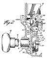
- is a side view of an actuator assembly, in accordance with the invention, shown in its rest condition, portions thereof being shown in section;
- FIGURE 2
- is a view similar to Figure 1 with the actuator assembly in its actuated condition;
- FIGURE 3
- is a rear view of the embodiment of Figure 1, partially in section;
- FIGURE 4
- is an exploded perspective view of the clutch mechanism;
- FIGURE 5
- illustrates the facing surfaces of the input and outputs discs of the clutch mechanism;
- FIGURE 6
- is a perspective view of the mechanism as seen from the rear;
- FIGURE 7
- is a perspective view of the dual function cam member per se;
- FIGURE 8
- is a perspective view of the slider member per se; and
- FIGURE 9
- is a flow chart illustrating the logic for the timing means.
- Referring now to the drawings, the actuator includes a clutch mechanism, illustrated generally at 1, and means illustrated generally at 3 for effecting a rotation transmitting connection of the clutch mechanism. The actuator is housed in a
casing 5 having an opening 7 therethrough at the front of the actuator. Aknob sleeve 9, which is spring loaded, by means not shown, to return to its initial position extends through the opening and is in rotation transmitting communication with a connecting member 11 at the input of the clutch. - A
shaft receiving member 13 is disposed at the output side of the clutch. The clutch is housed in aclutch housing 15. - Referring to Figure 4, the clutch member includes an
input disc 17, which is connected to the input connecting member 11, for rotation therewith and anoutput disc 19, which is connected to theshaft receiving member 13 for rotation therewith. The connecting member 11 is connected toknob sleeve 9 for rotation therewith so thatinput disc 17 rotates with the rotation ofknob sleeve 9. - As the facing surfaces of both input and output discs are identical, only the facing surface of the ouput disc is shown in Figure 5 to illustrate the facing surfaces of both input and output discs.
- The facing surfaces of both the input and output discs includes diametrically opposed
abutments 21 having bevelledsurfaces 23 at their terminating edges. The abutments are disposed on alower surface 24 and are preferably formed integrally with the lower surface. - Returning to Figure 4, disposed in the clutch cover is a
spring means 25 which urges the output disc against the input disc. Closing slot means comprising, for example,slots 27 are disposed on diametrically opposed peripheral surfaces of theoutput disc 19, and the closing slots are in alignment withopenings 28 of thecover 15. Theopenings 28 overlie theslots 27. - The clutch mechanism operates in a manner well known in the art, namely, with the
spring 25 urging the output disc against the input disc, and with the abutments of the input disc being arranged to be located on the lower surfaces of the output disc, and vice-versa, when the input disc is rotated, the output disc will also rotate. However, if the output disc is held against rotation, for example, by applying fixed means in theclosing slots 27 thereof, rotation of the output disc will not be possible even when the input disc is rotated. Instead, the bevelled surfaces of the input disc will cam with the bevelled surfaces of the output disc to push the output disc rearwardly against the force of thespring 25. Thus, the rotation of the input disc will still be possible, however, the rotation of the input disc will, in this condition, not be transmitted to the output disc. - Returning now to Figure 1, 2 and 3, the
means 3 for effecting a rotation transmitting connection of the clutch comprises apivoting fork 29. The pivoting fork is mounted for pivoting about a fixedpivot point 31 and includeslocking pins 33 at thelower edges 35 thereof. The lower end of the pivoting fork comprises leg means, comprising, for example,legs 37 which straddle the clutch mechanism 1 as best seen in Figure 3. As can also be seen in Figure 3, in one position of the pivoting fork, the locking pins 33 are located in theclosing slots 27 to hold the output disc against rotation. - The top end of the pivoting fork comprises an
abutment end 39 to be discussed below. Spring means, illustrated diagramatically at 40 in Figures 1 and 2 urge the fork means into its rest condition as shown in Figure 1. - Extending from opening 41 in
fork 29 are a lockinglever 43 and and afork holding lever 45. Thelevers shaft 47 carried by thefork 29. Although the levers are biassed in a downward direction by the force of gravity alone, it is preferable to provide a spring means, illustrated diagrammatically at 49 in Figure 3, to provide a positive bias of the levers in a downward direction. The front end oflever 43 includes a retainingdog 51, and a dependingabutment member 53 is provided on the lower edge oflever 45. - Disposed forward of the pivoting
fork 29 is a mountingplate 55 fixed with respect to thecasing 5. The position of the mounting plate is illustrated in Figures 1 and 2, and the mounting plate is per se illustrated in greater detail in Figure 6. Turning to Figure 6, the mounting plate includes abottom opening 57 through which thelevers platform 59 is contructed at the top of the mounting plate and supports a rotating mechanism, such as a motor, 61. - The mounting plate also includes a
top opening 63 in which is mounted a dualfunction cam member 65. - The dual function cam member is illustrated in greater detail in Figure 7 and it includes a
top surface 67 havingabutments 69 mounted onrest surface 70. Preferably, the abutments are formed integrally with the rest surface. - The edges of the abutments are terminated by bevelled
surfaces 71 at the attack end thereof. - Depending from the bottom surface of the dual function cam member is an
eccentric cam 73 having aradially extending arm 74. Extending from the top surface is amotor connecting shaft 75. - Referring to Figure 3, disposed in front of the pivoting fork and behind the support plate is a vertically
movable slider member 77. The slider member, which is illustrated in more detail in Figure 8, includesarms 79 which, as can be seen in Figures 1, 2 and 3, are disposed horizontally over the dual function cam member. Thearms 79 are connected, by vertically connectingmembers 81, to atransverse bottom strip 83 to defineopening 77A. Extending downwardly from the bottom strip is aslider nose 85. As seen in Figure 3, thenose 85 extends into anindent 87 in theoutput disc 19. - The
slider nose 85 can extend into theindent 87 because thehousing 15 does not cover the top part of theoutput disc 19. The bottom part of the output disc is covered by therear bottom extension 89 of thehousing 15, however, as seen in Figure 4, the top of theoutput disc 19 remains uncovered. - As seen in Figure 3, the top surface of the
bottom strip 83 underlies the bottom surface of theopening 57 in the supporting plate so that, when the slider member moves upwardly, it will contact thelevers spring 49. - In operation, the actuator assembly works as follows:
In the rest condition, as illustrated in Figure 1, the retainingdog 51 onlever 43 overlies the front surface of the bottom edge of opening 57 to thereby restrain pivoting motion of the pivotingfork 29. In addition, thearms 79 of theslider member 77 rest on therest surface 70 of the dual function cam member. Thus, as seen in Figure 1, thebottom strip 83 of the slider member does not make contact with thelevers - The
lever 45 is maintained in an upward position by contact of the dependingmember 53 on the bottom edge of theopening 57. - In the rest position, as seen in Figure 1, the
arm 74 of theeccentric cam 73 faces away from theabutment end 39 of the pivotingfork 29, and the latter bears against the concentric surface ofcam 73. - In the rest condition, locking pins 33 are disposed in the
closing slots 27 of the output disc of the clutch mechanism, as seen in Figure 3, so that rotation of the input disc, which is transmitted thereto by rotation of theknob sleeve 9, will not be transmitted to theoutput disc 19. - When the actuator is in the rest position illustrated in Figure 1, the slider arms, resting as they do on the
surface 70, place theslider member 77 in its downward position. In this position, thenose 85 of the slider member extends into theindent 87 of theoutput disc 19. However, as the slider member is free-moving, this does not prevent the rotating motion of the output disc. Instead, as above-mentioned, it is the disposition of the locking pins 33 in theclosing slots 27 of the output disc which prevents rotation of the output disc. - When the
motor 61 is actuated, it will cause theshaft 75 to rotate the dualfunction cam member 65. Accordingly, the bevelled surfaces 71 of the cam member will engage thearms 79 of the slider member to raise the slider member. This will bring thebottom strip 83 of the slider member in contact withlever 43 raising this lever so that the retainingdog 51 of the lever is raised above the bottom surface of theopening 57 thus freeing the pivotingfork 29. - At the same time, the
arm 74 of theeccentric cam 73 will contactabutment end 39 of the pivoting fork and will force the abutment end to move rearwardly . When the abutment end of the pivoting fork moves rearwardly, because of the pivoting motion, the bottom end of the pivoting fork will move forwardly to a position as shown in Figure 2. As can be seen in Figure 2, with the pivoting fork pivoted out of its rest condition into the actuated condition, the locking pins 33 are moved out of the closingslots 27 so that theoutput disc 19 is no longer restrained. Accordingly, rotation motion of the input disc will now be transmitted to the output disc thereby effecting a rotation transmitting connection of the clutch mechanism. - As seen in Figure 2, when the actuator is in its actuated condition, the front edge of the depending
member 53 onlever 45 engages with the inner surface adjacent the bottom edge of theopening 57 in the mountingplate 55 to thereby prevent the pivotingfork 29 from returning to its rest condition by action of thespring 40. It is also noted that the dual function cam member is rotated through a large enough angle so that, in the actuating condition, theslider member 77 once again moves downwardly, and thenose 85 of the slider member is once again disposed in theindent 87 of the output disc. However, as above-mentioned, as the slider member is free-moving, this will not restrain the rotary motion of the output disc. In addition,arm 74 will face away fromabutment 39 so thatarm 74 will not prevent forward movement offork 29. - The motor is actuated by means, shown diagrammatically at 100 in Figures 1 and 2, which is connected to the motor by means well known in the art but not shown in the drawings. The means 100 can comprise a keyed mechanism or an electronic or mechanical numerical combination means or other means well known in the art, and the actuating means will, as well known in the art, provide power to the motor when appropriate action is taken.
- The actuating assembly will remain in its actuated condition until such time as the slider member is once again lifted upwardly. This can be accomplished in one of two ways.
- 1). By rotating the knob sleeve to thereby rotate, through the agency of the connecting member 11, the
input disc 17, of the clutch mechanism. When the input disc is rotated, the output disc will also be rotated to thereby force thenose 85 of the slider member out of theindent 87 and to lift it onto the outer peripheral surface of the output disc. This lifting action of the nose of the slider member will, of course, move the slider member itself upwardly so that thebottom strip 83 of the slider member will lift thefork holding lever 45 by making contact with the bottom edge of its dependingabutment member 53. Accordingly, withlever 45 raised so that the dependingabutment member 53 is above the top edge of theopening 57, pivotingfork 29 will be free to return to its rest position, and will return there because of the action of the spring means 40.
When the spring loadedknob sleeve 9 is released, it returns to its initial position so that the input disc will return to its initial position and the output disc will also return to its initial position, so that thenose 85 of the sliding member will once again fall into theindent 87 of the output disc. Accordingly, thearms 79 will once again rest on thesurface 70 of the dual function cam member, and the sliding member will be in its lower position. Thus, the entire actuating assembly will have returned to its rest condition as illustrated in Figure 1. During this procedure, themotor 61 is not actuated so thatdual function cam 65 does not rotate. - 2.) Alternatively, the slider member can be lifted through the agency of a timing means illustrated diagrammatically at 101 in Figures 1 and 2. The timing means will, after a predeterminated delay, and in the face of non-rotation of the
knob sleeve 9, once again actuate themotor 61 to rotate it through a further predeterminate angle, i.e., a minimum of 90° and a maximum of 180°. Once again, the slider member will be raised when thearms 79 slide up the bevelled surfaces 71 of the dual function cam member and then ride along the top of theabutment 69. This raising of the sliding member will have the same effect as the raising of the sliding member due to the action of thenose 85 being forced out of theindent 87, so that the timing means will also force the actuator assembly back to its rest condition. - In the absence of a timing mechanism as above-described, if someone should actuate the
motor 61, for example, by using a proper key or a correct combination or the like, and then neglect to rotate the knob sleeve, the actuator assembly would remain in its actuated condition indefinitely possibly permitting unauthorized entry at a later time. Thus, providing the timing means provides an extra safety feature in accordance with the invention. - The knob sleeve is connected to, for example, a
door knob 10 or the like for rotation, and the shaft receiving member is connected to the shaft of, for example, a latch mechanism or the like to retract the latch as is well known in the art. With the inventive actuator assembly, it can be seen that the lock is automatically self-closing either after a single opening or after a predetermined time delay. Accordingly, it is especially advantageous in preventing unauthorized entry. In addition, as the actuation is initiated by an electrical signal, the initiation means cam comprise a combination mechanism with changeable combinations. - Further, the provision of the
lever 43 to restrain thefork 29 from pivoting motion when the assembly is in its rest condition provides an added measure of security in accordance with the invention. Although spring means 40 will urgefork 29 into its rest position to thereby maintain thepins 33 inslots 27, vibrations or jarring forces applied to the mechanisms could overcome the force of the spring to permit the pins to slide out of the slots. The action oflever 43, when it is in its rest condition, prevents this. - Although in the illustrated embodiment, pins 33 extend from
legs 37 intoslots 27 onoutput disc 19, it will be apparent that the pin and slot arrangement could be reversed, i.e., the pins could be on theouput disc 19 and the slots on thelegs 37. Or other means could be used to prohibit the rotation of the output disc when the assembly is in the rest condition. In addition, it is not necessary that there be twolegs 37 as a single leg is sufficient. - Considering the timing means, as such timing means will readily be constructed from available components by one skilled in the art, it is more instructive to discuss a flow chart illustrating the logic of such a timing means rather than describing a particular circuit. For this purpose, attention is directed to Figure 9.
- The first step is to determine when the actuator assembly is in its actuated condition. For this purpose, a sensor, for example, a microswitch, illustrated schematically at 1000 in Figures 1 and 2, and mounted on the
casing 55 adjacent the dualfunction cam assembly 65 could be employed. For example, in the case of a microswitch, the outer peripheral surface of thecam member 65 could press against the microswitch to keep it depressed at all times. A notch would be placed on the outer peripheral surface at such a position that the motor should be stopped when the notch is sensed by the microswitch. When the notch is so sensed, a signal is generated which tells the control circuitry that the assembly is now in its actuated condition. This signal is the control signal for stopping the motor. In this regard, when the assembly is actuated, the dual function cam assembly must be rotated through a large enough angle to raise the sliding member so that it lifts thelevers fork 29 to move rearwardly. It must also move through a large enough angle so that thearm 74 will push against theabutment member 39 to forcefork 29 rearwardly whilelevers arm 74 will move into a position such that it will not preventfork 29 from returning to its forward position, i.e., thearm 74 must not be pointing towards theabutment end 39. Thus, in Figure 2 it is illustrated as being rotated 90° from the position that it would be in if it were pointing to theabutment end 39. - When the motor stops, the security timing period is initiated.
- This action is represented in the topmost decision block of Figure 9.
- With the assembly in its actuated condition, it now remains to determine whether:
- 1. The handle is turned; or
- 2. The security timing period has elapsed.
- In order to determine the former, a sensor, such as a second microswitch illustrated schematically at 1001 in Figures 1 and 2, and which could be located on the inner top surface of the
opening 57 of the mountingplate 55, would be placed in such a position so that, when the levers are lifted, one of the levers will depress themicroswitch 1001. The sensing of the pressing of this microswitch will bypass the security timing action as seen in Figure 9. - If the security timing period elapses before the handle is moved, then a signal will be sent to turn the motor on to return the actuator assembly to its rest condition. At this time; dual
function cam member 65 must be rotated through an angle of between 90° and 180°, i.e., an angle large enough to ensure that theslider member 77 is lifted to lift thelevers arm 79 of the slidingmember 77 rest on thesurface 70 ofcam 65. The amount of time that the motor should run after the lapsing of the security timing period can be determined either by sensing the rotation of the dual function cam member 65 (for example, with a microswitch as previously), or it can be set to run for a given period of time. In the latter case, allowances would have to be made for the deterioration of the battery driving the motor as the motor will rotate at a greater speed when the battery is at its peak, than after the battery has deteriorated. Accordingly, the timing period for the motor in this case should be set to ensure that it does not run too far on a fully charged battery, and that it does run far enough after the battery has deteriorated. - The
arm 74 will not point in the same direction when the assembly arrives in its unactuated condition after returning of the handle as it will when the assembly arrives in its unactuated condition after an elapsing of the security timing. It is for this reason that a position sensor must be used to determine when the assembly has arrived in its actuated condition. - Although the description above refers to
microswitches - Although a single embodiment has been described, this was for the purpose of illustrating, but not limiting, the invention. Various modifications which will come readily to the mind of one skilled in the art are within the scope of the invention as defined in the appended claims.
Claims (12)
- A lock actuator assembly electrically activated and having a time delay action characterized in that it comprises:
a clutch mechanism (1) having an input disc (17) and an output disc (19) to be connected to an input shaft of a lock;
means (9, 10, 11) for rotating input disc;
means (3) for preventing rotation of said output disc with said input disc when said assembly is in a rest condition, and for effecting a rotation transmitting connection between said input disc and said output disc when said assembly is in an actuated condition;
means for automatically returning said assembly from said actuated condition to said rest condition: 1) if said input disc is rotated within a given time delay, upon said rotation when said assembly is actuated; or, (2) if said input disc is not rotated within said given time delay, upon the expiration of said time delay;
whereby, said output disc can be rotated only once within said time delay, and whereby said output disc is not rotatable if said input disc is not rotated within said time delay. - An assembly as defined in claim 1 characterized in that said means for preventing rotation of said output disc with said input disc comprises a pivoting fork, said pivoting fork (29) being pivotable from a first condition, when said assembly is in its rest condition, to a second condition, when said assembly is in its actuated condition, and vice-versa, said pivoting fork having leg means (37) straddling said clutch mechanism;
said leg means including restraining means (33) for restraining motion of said output disc when said assembly is in said rest condition. - An assembly as defined in claim 2 characterized in that (19) said output disc has closing slot means (27) on the peripheral surface thereof;
and said restraining means comprises locking pin means (33) on said leg means;
said locking pin means being disposed in said closing slot means when said fork is in said first condition whereby to restrain rotation of said output disc; and
said locking pin means being movable out of said closing slot means by the pivoting action of said pivoting fork (29) when said fork is moved to said second condition, whereby motion of said output disc is no longer restrained and rotation transmission of said input disc to said output disc is possible. - An assembly as defined in claim 3 characterized in that it further includes a mounting plate (55) substantially parallel to said pivoting fork when said pivoting fork is in said first condition;
an opening (41) in said pivoting fork (29) above the pivoting point (31) thereof for pivotally mounting a first lever (43) and a second lever (45);
a lever receiving opening (57) in said mounting plate (55), said levers, being adapted to extend through said lever receiving opening;
said first lever being adapted to maintain said fork in its first condition; and
said second lever being adapted to maintain said fork in its second condition. - An assembly as defined in claim 4 characterized in that said first lever (43) has a retaining dog (51) at the front end thereof which overlaps the bottom edge of the opening (57) of the mounting plate (55) at the surface of the mounting plate remote from said fork (29) to thereby prevent backward pivoting of said pivoting fork and thereby maintain said pivoting fork in said first condition; and
said second lever (45) having a depending abutment member (53) close to the pivoting end thereof which depending abutment member falls behind the back surface of the mounting plate (55) adjacent to said pivoting fork at the bottom edge of the opening of the mouting plate to thereby prevent forward pivoting of said fork and thereby maintain said fork in its second condition. - An assembly as defined in claim 5 characterized in that it further includes sliding member (77) movably mounted between said mounting plate (55) and said fork (24);
said sliding member being normally disposed in a downward position;
means for moving said sliding member upwardly to an upward position;
said sliding member having a bottom strip (83) disposed below said mounting plate opening (57) when said sliding member is in its downward position;
said bottom strip contacting the bottom edges of said levers (43, 45) and forcing then upwardly when the sliding member is moved upwardly;
whereby, when the sliding member is in its upward position, the bottom edges of said depending abutment member (53) and said retaining dog (51) are above the bottom edge of said opening in said mounting plate, so that said pivoting fork is free to pivot. - An assembly as defined in claim 6 characterized in that it further includes a dual function cam member (65), including;
first means (71) for moving said sliding member upwardly; and
second means (73, 74) for forcing the top end of the pivoting fork backwardly to thereby cause said pivoting fork to pivot backwardly, away from the mounting plate (55). - An assembly as defined in claim 7 characterized in that said cam member (65) has a circular top surface (67),
and wherein said sliding member (77) has cross arms (79) at the top end thereof extending across the top surface of the cam member;A) said first means (71) comprising, on said top surface (67),(1) a lower or rest surface (70)(2) abutments (69) above the lower surface defining a higher surface, said abutments being terminated in bevelled surfaces (71) at the attack end thereof,
whereby, said arms (79) normally rest on said lower surface, and whereby, when said cam member (65) is rotated, said arms slide along said bevelled surfaces onto said abutments to thereby move said sliding member from said downward position to said upward position;B) said second means (73, 74) comprising a cam member (73) extending downwardly from said top surface and having an arm (74) for contacting the top end of the pivoting fork (29), when said cam member is rotated, and forcing the top end of the pivoting fork backwards to thereby cause said pivoting fork to pivot backwards. - An assembly as defined in claim 8 characterized in that further includes motor means (61), mounted above said dual function cam means (65), for rotating said cam means;
said motor means being actuatable by a keyed mechanism or a numerical combination means (100),
said motor means being further actuatable by a timing mechanism (101) actuated by said keyed mechanism or numerical combination means. - An assembly as defined anyone of the preceding claims, characterized in that it includes an indent (89) in the top peripheral surface of said output disc (15);
a nose (85) extending downwardly from the bottom edge of said sliding member being disposed in said indent when said sliding member is in its downward position;
said nose being forced out of said indent and upwardly when said output disc is rotated;
whereby to move said sliding member upwardly to its upward position. - An assembly as defined in any one of the preceding claims, characterized in that said means for rotating said input disc comprises a door knob (10).
- An assembly as defined in any one of the preceding claims, characterized in that said means for automatically returning comprises; means (1000) for sensing when said assembly is in its actuated condition;
means for turning off said motor means when said above condition is sensed;
means (1001) for sensing when said means (10) is turned after the above condition has been sensed whereby said assembly is returned to its rest condition;
means for sensing the elapse of said time delay after the first condition has been sensed, whereupon said motor is turned on to return the assembly to its rest condition.
Priority Applications (2)
| Application Number | Priority Date | Filing Date | Title |
|---|---|---|---|
| DE8686107344T DE3683289D1 (en) | 1986-05-30 | 1986-05-30 | LOCK ACTUATOR. |
| AT86107344T ATE71174T1 (en) | 1986-05-30 | 1986-05-30 | LOCK CONTROL DEVICE. |
Applications Claiming Priority (1)
| Application Number | Priority Date | Filing Date | Title |
|---|---|---|---|
| US06/593,833 US4592453A (en) | 1984-03-27 | 1984-03-27 | Lock actuator assembly |
Publications (2)
| Publication Number | Publication Date |
|---|---|
| EP0248095A1 EP0248095A1 (en) | 1987-12-09 |
| EP0248095B1 true EP0248095B1 (en) | 1992-01-02 |
Family
ID=24376383
Family Applications (1)
| Application Number | Title | Priority Date | Filing Date |
|---|---|---|---|
| EP86107344A Expired - Lifetime EP0248095B1 (en) | 1984-03-27 | 1986-05-30 | Lock actuator assembly |
Country Status (4)
| Country | Link |
|---|---|
| US (1) | US4592453A (en) |
| EP (1) | EP0248095B1 (en) |
| AU (1) | AU581086B2 (en) |
| CA (1) | CA1235438A (en) |
Families Citing this family (6)
| Publication number | Priority date | Publication date | Assignee | Title |
|---|---|---|---|---|
| US4592453A (en) * | 1984-03-27 | 1986-06-03 | Ilco Unican Inc. | Lock actuator assembly |
| US4916299A (en) * | 1985-09-24 | 1990-04-10 | Ilco Unican Inc. | Card recepticle housing |
| US4762212A (en) * | 1985-09-24 | 1988-08-09 | Ilco Unican Inc. | Lock actuator assembly and card reader |
| US4799719A (en) * | 1987-06-18 | 1989-01-24 | George Wood | Motor operated lock |
| FR2746132B1 (en) * | 1996-03-14 | 1998-06-12 | DEVICE FOR ELECTRICALLY LOCKING AND UNLOCKING A LOCK MEMBER AND LOCK EQUIPPED WITH SUCH A DEVICE | |
| US7963134B2 (en) * | 2003-08-20 | 2011-06-21 | Master Lock Company Llc | Deadbolt lock |
Family Cites Families (13)
| Publication number | Priority date | Publication date | Assignee | Title |
|---|---|---|---|---|
| US1516152A (en) * | 1923-04-23 | 1924-11-18 | Joseph R Dumont | Doorknob |
| US2318908A (en) * | 1941-03-08 | 1943-05-11 | American Hardware Corp | Lock |
| US2936052A (en) * | 1956-06-21 | 1960-05-10 | Ca Atomic Energy Ltd | Combined control of motor and clutch |
| DE1553485A1 (en) * | 1964-08-01 | 1970-03-19 | Ernst Steffe | Automatic door opener |
| GB1440576A (en) * | 1972-07-05 | 1976-06-23 | Lucas Industries Ltd | Actuator device for use in a gas turbine engine fuel system |
| CA967614A (en) * | 1972-07-17 | 1975-05-13 | Hans Keller | Delay action time lock |
| US3982129A (en) * | 1974-11-22 | 1976-09-21 | The United States Of America As Represented By The United States Energy Research And Development Administration | Method and means of monitoring the effluent from nuclear facilities |
| US4196347A (en) * | 1978-07-10 | 1980-04-01 | Chubb & Son's Lock And Safe Company Limited | Security systems |
| US4269050A (en) * | 1978-09-07 | 1981-05-26 | Sargent & Greenleaf, Inc. | Time lock with kicker arm carrier actuator |
| DE2942852A1 (en) * | 1979-10-24 | 1981-05-07 | Vdo Adolf Schindling Ag, 6000 Frankfurt | DEVICE FOR UNLOCKING AND LOCKING DOORS |
| US4394821A (en) * | 1981-06-05 | 1983-07-26 | Best Lock Corporation | Door lock mechanism |
| JPS5857335U (en) * | 1981-10-12 | 1983-04-18 | 株式会社小松製作所 | Feeder drive device |
| US4592453A (en) * | 1984-03-27 | 1986-06-03 | Ilco Unican Inc. | Lock actuator assembly |
-
1984
- 1984-03-27 US US06/593,833 patent/US4592453A/en not_active Expired - Lifetime
- 1984-06-07 CA CA000456106A patent/CA1235438A/en not_active Expired
-
1986
- 1986-05-27 AU AU57971/86A patent/AU581086B2/en not_active Ceased
- 1986-05-30 EP EP86107344A patent/EP0248095B1/en not_active Expired - Lifetime
Also Published As
| Publication number | Publication date |
|---|---|
| US4592453A (en) | 1986-06-03 |
| AU581086B2 (en) | 1989-02-09 |
| AU5797186A (en) | 1987-12-03 |
| EP0248095A1 (en) | 1987-12-09 |
| CA1235438A (en) | 1988-04-19 |
Similar Documents
| Publication | Publication Date | Title |
|---|---|---|
| CA1282607C (en) | Combination/electronic lock system | |
| EP0219694B1 (en) | Lock actuator assembly and card reader | |
| US4685709A (en) | Deadlocked latch having disc and motor actuators | |
| US7010947B2 (en) | Remote door entry system | |
| US6435573B1 (en) | Rotating catch lock, specially for motor vehicles | |
| US4529234A (en) | Electrical operating means for door lock mechanisms | |
| US5934717A (en) | Motor Vehicle lid or door lock | |
| AU1527000A (en) | Electric lock | |
| EP0463088B1 (en) | An electrically operated securing plate for door locks | |
| KR20140139502A (en) | Motor vehicle door lock and method for electrically actuating a locking mechanism | |
| EP0248095B1 (en) | Lock actuator assembly | |
| EP0896118A1 (en) | Vehicle door lock with electrical locking device | |
| US5517006A (en) | Microwave oven with a door locking system | |
| KR960011949B1 (en) | Mechanical lock and key | |
| JP2001508509A (en) | Engraved lock | |
| EP1862616A1 (en) | Safety lock for doors of dwellings, gates and the like | |
| FR2536108A1 (en) | SECURITY LOCK FOR MAIN DOOR OF A LOCAL, SUCH AS AN APARTMENT | |
| US4640110A (en) | Automatic delay relocking device | |
| EP0333588B1 (en) | Automatic safety locking device | |
| US5307655A (en) | Timed triggering control device for a mechanism | |
| CA2401162C (en) | Closing sheet for escape doors | |
| US6360572B1 (en) | Motor vehicle opening leaf handle comprising operated disengageable means for operating a lock | |
| CA2017150C (en) | Delay action electronic timer lock with automatic cancellation cam | |
| GB2387872A (en) | Rotary locking device | |
| EP0262262B1 (en) | Device for actuating a safety-lock and lock comprising such a device |
Legal Events
| Date | Code | Title | Description |
|---|---|---|---|
| PUAI | Public reference made under article 153(3) epc to a published international application that has entered the european phase |
Free format text: ORIGINAL CODE: 0009012 |
|
| AK | Designated contracting states |
Kind code of ref document: A1 Designated state(s): AT BE CH DE FR GB IT LI LU NL SE |
|
| 17P | Request for examination filed |
Effective date: 19880608 |
|
| 17Q | First examination report despatched |
Effective date: 19890216 |
|
| GRAA | (expected) grant |
Free format text: ORIGINAL CODE: 0009210 |
|
| AK | Designated contracting states |
Kind code of ref document: B1 Designated state(s): AT BE CH DE FR GB IT LI LU NL SE |
|
| PG25 | Lapsed in a contracting state [announced via postgrant information from national office to epo] |
Ref country code: SE Effective date: 19920102 Ref country code: BE Effective date: 19920102 Ref country code: AT Effective date: 19920102 |
|
| REF | Corresponds to: |
Ref document number: 71174 Country of ref document: AT Date of ref document: 19920115 Kind code of ref document: T |
|
| ET | Fr: translation filed | ||
| REF | Corresponds to: |
Ref document number: 3683289 Country of ref document: DE Date of ref document: 19920213 |
|
| ITF | It: translation for a ep patent filed | ||
| PG25 | Lapsed in a contracting state [announced via postgrant information from national office to epo] |
Ref country code: NL Effective date: 19920417 |
|
| PG25 | Lapsed in a contracting state [announced via postgrant information from national office to epo] |
Ref country code: LU Free format text: LAPSE BECAUSE OF NON-PAYMENT OF DUE FEES Effective date: 19920531 Ref country code: LI Effective date: 19920531 Ref country code: CH Effective date: 19920531 |
|
| PGFP | Annual fee paid to national office [announced via postgrant information from national office to epo] |
Ref country code: DE Payment date: 19920720 Year of fee payment: 7 |
|
| PLBE | No opposition filed within time limit |
Free format text: ORIGINAL CODE: 0009261 |
|
| STAA | Information on the status of an ep patent application or granted ep patent |
Free format text: STATUS: NO OPPOSITION FILED WITHIN TIME LIMIT |
|
| 26N | No opposition filed | ||
| REG | Reference to a national code |
Ref country code: CH Ref legal event code: PL |
|
| PG25 | Lapsed in a contracting state [announced via postgrant information from national office to epo] |
Ref country code: DE Effective date: 19940201 |
|
| PGFP | Annual fee paid to national office [announced via postgrant information from national office to epo] |
Ref country code: GB Payment date: 19960509 Year of fee payment: 11 |
|
| PGFP | Annual fee paid to national office [announced via postgrant information from national office to epo] |
Ref country code: FR Payment date: 19960523 Year of fee payment: 11 |
|
| PG25 | Lapsed in a contracting state [announced via postgrant information from national office to epo] |
Ref country code: GB Effective date: 19970530 |
|
| GBPC | Gb: european patent ceased through non-payment of renewal fee |
Effective date: 19970530 |
|
| PG25 | Lapsed in a contracting state [announced via postgrant information from national office to epo] |
Ref country code: FR Free format text: LAPSE BECAUSE OF NON-PAYMENT OF DUE FEES Effective date: 19980130 |
|
| REG | Reference to a national code |
Ref country code: FR Ref legal event code: ST |
|
| PG25 | Lapsed in a contracting state [announced via postgrant information from national office to epo] |
Ref country code: IT Free format text: LAPSE BECAUSE OF NON-PAYMENT OF DUE FEES;WARNING: LAPSES OF ITALIAN PATENTS WITH EFFECTIVE DATE BEFORE 2007 MAY HAVE OCCURRED AT ANY TIME BEFORE 2007. THE CORRECT EFFECTIVE DATE MAY BE DIFFERENT FROM THE ONE RECORDED. Effective date: 20050530 |