EP0219030A2 - Strumpfrundstrickmaschine mit Schutzhaube in der Strickzone - Google Patents
Strumpfrundstrickmaschine mit Schutzhaube in der Strickzone Download PDFInfo
- Publication number
- EP0219030A2 EP0219030A2 EP86113818A EP86113818A EP0219030A2 EP 0219030 A2 EP0219030 A2 EP 0219030A2 EP 86113818 A EP86113818 A EP 86113818A EP 86113818 A EP86113818 A EP 86113818A EP 0219030 A2 EP0219030 A2 EP 0219030A2
- Authority
- EP
- European Patent Office
- Prior art keywords
- machine
- machine according
- containment body
- parts
- chamber
- Prior art date
- Legal status (The legal status is an assumption and is not a legal conclusion. Google has not performed a legal analysis and makes no representation as to the accuracy of the status listed.)
- Withdrawn
Links
Images

Classifications
-
- D—TEXTILES; PAPER
- D04—BRAIDING; LACE-MAKING; KNITTING; TRIMMINGS; NON-WOVEN FABRICS
- D04B—KNITTING
- D04B35/00—Details of, or auxiliary devices incorporated in, knitting machines, not otherwise provided for
- D04B35/32—Devices for removing lint or fluff
-
- D—TEXTILES; PAPER
- D04—BRAIDING; LACE-MAKING; KNITTING; TRIMMINGS; NON-WOVEN FABRICS
- D04B—KNITTING
- D04B15/00—Details of, or auxiliary devices incorporated in, weft knitting machines, restricted to machines of this kind
Definitions
- the present invention relates to a circular knitting machine for producing stockings and the like with a protective screen in the processing area.
- Circular machines are known for producing stockings with protective screens in the processing zone to prevent oil, employed for the lubrication of the various devices acting on the needle-bearing cylinder and on the other elements of the machine in this region, from being spewed out of the machine onto the operators or the surrounding environment.
- these protection screens are composed of walls, arranged around the needle-bearing cylinder, which are higher than the needle-bearing cylinder and can be removed to allow the operator to gain access to the various elements.
- These walls are in transparent material, in order to allow the operator to monitor the operation of the elements of the machine in the processing region and are supported by an oil-collecting tray.
- the main aim of the present invention is to provide a circular knitting machine for stockings and the like with a protective screen in the processing area which constitutes a barrier against the spewing of oil and achieves an attenuation of the noise produced by the machine.
- an object of the invention is to provide a protective screen which isolates the processing area from possible infitration of dirt from outside.
- a circular knitting machine for producing stockings and the like with a protective screen in the processing area, characterized in that it comprises a containment body extending around and above the needle-bearing cylinder to define a chamber containing said needle-bearing cylinder and isolatable from the environment surrounding the machine, said containment body having a lateral surface provided in at least two parts of which at least one is movable with respect to the other for opening or closing said chamber, means being provided for the passage of threads passing through said containment body for feeding the machine.
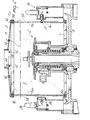
- the machine for producing stockings and the like comprises a containment body in transparent material, generally designated with the reference numeral 1, which extends around and above the needle-bearing cylinder 2 so as to define a chamber 3 which indeed contains the needle-bearing cylinder and is isolated from the environment surrounding the machine.
- the containment body 1 has a lateral surface, substantially in the shape of a cylinder, upwardly covered by a roof 4 which, in the illustrated embodiment, is slightly conical, but may also be plane, dome-shaped, etc.
- the lateral surface of the containment body is provided in at least two parts 5a and 5b of which at least one is slideable with respect to the other to open and close the chamber 3.
- the parts 5a and 5b substantially correspond to a half cylinder cut along a plane containing the axis and have curvature radii slightly different from one another so that one can slide superimposing itself on the other by rotating around the axis of the cylinder.
- parts 5a and 5b are slideable within guiding means composed of a pair of lower grooves 6a and 6b, which are defined in a first ring 7 associated with the supporting frame of the machine above the oil-collecting tray 8, and of a pair of upper grooves 9a and 9b which are defined on a second ring 10 which can be associated with the supporting structure of the machine or with the lower edge of the roof 4.
- Each pair of grooves is composed of two grooves extending coaxially to the containment body along circular paths with curvature radii which are slightly different from one another so as to slideably accommodate the ends of parts 5a and 5b which in this mannner are rotatable around a same axis, but with opposite directions of rotation, to obtain the opening or the closing of the chamber 3.
- means are provided for the passage of the threads 11 which from the spools reach the various feeds of the machine.
- These means are composed of a plurality of holes 12 which traverse the roof 4 of the containment body 1.
- anti-wear material such as ceramic material.
- the roof 4 can furthermore be provided with an opening 13 which, through a conduit 14, connects the chamber 3 with an area remote with respect to the machine, such as, e.g., the outside of the room in which the machine is arranged.
- an aspiration device By placing on this conduit an aspiration device, not illustrated in the figures for the sake of clarity, an aspirating current can be created in the chamber, which removes pieces of thread, or more generally dirt accidentally penetrated inside the chamber 3, so as to always keep the processing area clean.
- a locking device 15 can be provided, mounted laterally with respect to the containment body 1 and composed of a magnetic-field detector 16 associated with the supporting strucure of the machine and of a plate 17 in ferromagnetic material associated with one of the parts 5a or 5b so that, with the chamber 3 closed, the plate 17 faces the magnetic-field detector.
- the magnetic-field detector is connected in a known manner to the main switch of the machine so that, with the chamber 3 open, it is not possible to activate the machine.
- detents or stop elements 18 can be provided, e. . g. of the ball-and-spring type, to indicate the perfect closing of the chamber 3.
- a lamp 19 can also be provided in a known manner for illuminating the processing area, as well as a machine halt indicator 20.
- the containment body according to the invention fully achieves the intended aim by providing a protective screen which prevents oil from being spewed out from the machine and at the same time attenuates the noise of the machine.
- Another advantage originating from the fact that the chamber thus defined can be connected to an aspirator, is that the processing area of the machine is kept clean.
- a not least advantage is that the moving parts of the machine are enclosed in the containment body according to the invention and that the activation of the machine is prevented when the containment body is not completely closed, to the full advantage of the safety of the operator.
Landscapes
- Engineering & Computer Science (AREA)
- Textile Engineering (AREA)
- Knitting Machines (AREA)
- Treatment Of Fiber Materials (AREA)
Applications Claiming Priority (2)
| Application Number | Priority Date | Filing Date | Title |
|---|---|---|---|
| IT2340885U | 1985-10-14 | ||
| IT8523408U IT209232Z2 (it) | 1985-10-14 | 1985-10-14 | Macchina circolare per laproduzione di calze e simili con schermo di protezione nella zona di lavorazione. |
Publications (2)
| Publication Number | Publication Date |
|---|---|
| EP0219030A2 true EP0219030A2 (de) | 1987-04-22 |
| EP0219030A3 EP0219030A3 (de) | 1987-12-02 |
Family
ID=11206823
Family Applications (1)
| Application Number | Title | Priority Date | Filing Date |
|---|---|---|---|
| EP86113818A Withdrawn EP0219030A3 (de) | 1985-10-14 | 1986-10-06 | Strumpfrundstrickmaschine mit Schutzhaube in der Strickzone |
Country Status (5)
| Country | Link |
|---|---|
| US (1) | US4718253A (de) |
| EP (1) | EP0219030A3 (de) |
| JP (1) | JPS6290355A (de) |
| CS (1) | CS266338B2 (de) |
| IT (1) | IT209232Z2 (de) |
Cited By (3)
| Publication number | Priority date | Publication date | Assignee | Title |
|---|---|---|---|---|
| EP0301685A2 (de) * | 1987-07-27 | 1989-02-01 | Monarch Knitting Machinery Corporation | Rundstrickmaschine mit Tuchaufwickelsicherheitstür |
| EP1357215A1 (de) * | 2002-04-22 | 2003-10-29 | SIPRA Patententwicklungs- und Beteiligungsgesellschaft mbH | Rundstrickmaschine und dafür geeignete Schutzvorrichtung |
| CN105463690A (zh) * | 2016-01-20 | 2016-04-06 | 绍兴汉翔精密机械制造有限公司 | 一种高速丝袜机新型油泵传动装置 |
Families Citing this family (9)
| Publication number | Priority date | Publication date | Assignee | Title |
|---|---|---|---|---|
| JPH06101146A (ja) * | 1992-09-18 | 1994-04-12 | Fukuhara Seiki Seisakusho:Kk | 丸編機における繊維屑などの吸塵・排出装置 |
| EP0674033B1 (de) * | 1994-03-14 | 1998-12-23 | Lube Corporation | Verfahren und Vorrichtung zum Schmieren für eine Rundstrickmaschine |
| US5737942A (en) * | 1996-07-03 | 1998-04-14 | Alandale Industries, Inc. | Means for deterring lint and debris accumulation on the knitting elements of a circular knitting machine |
| US5956977A (en) * | 1997-07-14 | 1999-09-28 | Uniwave, Inc. | Dust control and cooling apparatus for circular knitting machines |
| DE19924217B4 (de) * | 1999-05-27 | 2006-03-23 | Huo-Wang Lin | Schutztür für Strickmaschinen |
| DE29909339U1 (de) * | 1999-05-28 | 1999-08-05 | Mayer Textilmaschf | Kettenwirkmaschine |
| US6735988B1 (en) | 2002-03-27 | 2004-05-18 | Honeycutt Larry W | Cotton footie and stocking |
| DE102014109303A1 (de) * | 2014-07-03 | 2016-01-07 | Sipra Patententwicklungs- Und Beteiligungsgesellschaft Mbh | Altölaufbereitungseinrichtung für eine Rundstrickmaschine |
| CN107002325B (zh) | 2014-12-09 | 2019-08-16 | 罗纳地股份公司 | 用于袜类的圆形针织机器的基脚 |
Citations (2)
| Publication number | Priority date | Publication date | Assignee | Title |
|---|---|---|---|---|
| US3146572A (en) * | 1961-03-30 | 1964-09-01 | Keyser Johann Jacob | Textile machine with closed housing |
| DE2529729A1 (de) * | 1975-06-12 | 1976-12-16 | Sulzer Ag | Vorrichtung zum ueberdecken einer automatisch arbeitenden arbeitsmaschine |
Family Cites Families (3)
| Publication number | Priority date | Publication date | Assignee | Title |
|---|---|---|---|---|
| US2539137A (en) * | 1949-03-09 | 1951-01-23 | Laurence E Hunold | Knitting machine guard |
| BE653062A (de) * | 1963-09-12 | |||
| CH489653A (de) * | 1966-09-05 | 1970-04-30 | Luwa Ag | Vorrichtung zum pneumatischen Entstauben der Arbeitszone von zentralsymmetrischen Textilmaschinen |
-
1985
- 1985-10-14 IT IT8523408U patent/IT209232Z2/it active
-
1986
- 1986-10-06 EP EP86113818A patent/EP0219030A3/de not_active Withdrawn
- 1986-10-07 US US06/916,901 patent/US4718253A/en not_active Expired - Fee Related
- 1986-10-13 CS CS867394A patent/CS266338B2/cs unknown
- 1986-10-14 JP JP61242172A patent/JPS6290355A/ja active Pending
Patent Citations (2)
| Publication number | Priority date | Publication date | Assignee | Title |
|---|---|---|---|---|
| US3146572A (en) * | 1961-03-30 | 1964-09-01 | Keyser Johann Jacob | Textile machine with closed housing |
| DE2529729A1 (de) * | 1975-06-12 | 1976-12-16 | Sulzer Ag | Vorrichtung zum ueberdecken einer automatisch arbeitenden arbeitsmaschine |
Cited By (5)
| Publication number | Priority date | Publication date | Assignee | Title |
|---|---|---|---|---|
| EP0301685A2 (de) * | 1987-07-27 | 1989-02-01 | Monarch Knitting Machinery Corporation | Rundstrickmaschine mit Tuchaufwickelsicherheitstür |
| EP0301685A3 (de) * | 1987-07-27 | 1991-04-03 | Monarch Knitting Machinery Corporation | Rundstrickmaschine mit Tuchaufwickelsicherheitstür |
| EP1357215A1 (de) * | 2002-04-22 | 2003-10-29 | SIPRA Patententwicklungs- und Beteiligungsgesellschaft mbH | Rundstrickmaschine und dafür geeignete Schutzvorrichtung |
| US6848278B2 (en) | 2002-04-22 | 2005-02-01 | Sipra Patententwicklungs- Und Beteiligungsgesellschaft Mbh | Circular knitting machine and protective device therefor |
| CN105463690A (zh) * | 2016-01-20 | 2016-04-06 | 绍兴汉翔精密机械制造有限公司 | 一种高速丝袜机新型油泵传动装置 |
Also Published As
| Publication number | Publication date |
|---|---|
| CS739486A2 (en) | 1988-03-15 |
| US4718253A (en) | 1988-01-12 |
| EP0219030A3 (de) | 1987-12-02 |
| JPS6290355A (ja) | 1987-04-24 |
| IT8523408V0 (it) | 1985-10-14 |
| CS266338B2 (en) | 1989-12-13 |
| IT209232Z2 (it) | 1988-09-20 |
Similar Documents
| Publication | Publication Date | Title |
|---|---|---|
| US4718253A (en) | Circular knitting machine for producing stockings and the like with a protective screen in the processing area | |
| KR101192065B1 (ko) | 먼지 제거 장치를 가지는 원형 편직기 | |
| DE3636182A1 (de) | Spinnaggregat einer oe-rotorspinnmaschine | |
| CA2193476A1 (en) | Knife | |
| US5379614A (en) | Dust and waste removal and collection system for double knitting machine | |
| US4792100A (en) | Apparatus and method for continuous spooling | |
| US4346497A (en) | Device for removing dust from a winding machine | |
| KR100345160B1 (ko) | 미싱의천칭가이드 | |
| US5613376A (en) | Thread cutting and aspiration unit for multiple-feed circular knitting machines | |
| US3977169A (en) | Sound reducing device in textile machine | |
| US2896434A (en) | Throat plate | |
| KR100319266B1 (ko) | 탄성사의 권취장치 및 권취방법 | |
| JP6061165B1 (ja) | ブレードマシンにおける給油型の面盤構造 | |
| US3778990A (en) | Device for open end spinning | |
| DE3543650C2 (de) | ||
| EP0517090B1 (de) | Fadenschneidvorrichtung für Doppelzylinder-Rundstrickmaschinen | |
| KR20010049341A (ko) | 경편기 | |
| KR102610534B1 (ko) | 포장용 목재 절단기 | |
| EP0957671B1 (de) | Vorrichtung und verfahren um ein gewächs wie hanf zu mähen und schneiden | |
| EP0692565B1 (de) | Verbesserung einer Fadenschneidvorrichtung an einer Strumpfrundstrickmaschine | |
| CN219752659U (zh) | 一种机头旋转模板机的挡油装置及缝纫机 | |
| KR830001928Y1 (ko) | 양말편직기의 공급사절단장치 | |
| JPH0217650B2 (de) | ||
| JP2002145528A (ja) | 紡糸糸条の巻取機 | |
| KR20220090002A (ko) | 절삭칩 침투 방지 커버를 구비한 자동 팔레트 교환장치 |
Legal Events
| Date | Code | Title | Description |
|---|---|---|---|
| PUAI | Public reference made under article 153(3) epc to a published international application that has entered the european phase |
Free format text: ORIGINAL CODE: 0009012 |
|
| AK | Designated contracting states |
Kind code of ref document: A2 Designated state(s): DE FR GB |
|
| PUAL | Search report despatched |
Free format text: ORIGINAL CODE: 0009013 |
|
| AK | Designated contracting states |
Kind code of ref document: A3 Designated state(s): DE FR GB |
|
| STAA | Information on the status of an ep patent application or granted ep patent |
Free format text: STATUS: THE APPLICATION IS DEEMED TO BE WITHDRAWN |
|
| 18D | Application deemed to be withdrawn |
Effective date: 19880606 |
|
| RIN1 | Information on inventor provided before grant (corrected) |
Inventor name: LONATI, FRANCESCO |