EP0218539A1 - Contact lenses cleaning and sterilizing apparatus - Google Patents
Contact lenses cleaning and sterilizing apparatus Download PDFInfo
- Publication number
- EP0218539A1 EP0218539A1 EP86450020A EP86450020A EP0218539A1 EP 0218539 A1 EP0218539 A1 EP 0218539A1 EP 86450020 A EP86450020 A EP 86450020A EP 86450020 A EP86450020 A EP 86450020A EP 0218539 A1 EP0218539 A1 EP 0218539A1
- Authority
- EP
- European Patent Office
- Prior art keywords
- cycle
- contact lenses
- solution
- rotary member
- plate
- Prior art date
- Legal status (The legal status is an assumption and is not a legal conclusion. Google has not performed a legal analysis and makes no representation as to the accuracy of the status listed.)
- Granted
Links
Images

Classifications
-
- G—PHYSICS
- G02—OPTICS
- G02C—SPECTACLES; SUNGLASSES OR GOGGLES INSOFAR AS THEY HAVE THE SAME FEATURES AS SPECTACLES; CONTACT LENSES
- G02C13/00—Assembling; Repairing; Cleaning
- G02C13/008—Devices specially adapted for cleaning contact lenses
-
- A—HUMAN NECESSITIES
- A61—MEDICAL OR VETERINARY SCIENCE; HYGIENE
- A61L—METHODS OR APPARATUS FOR STERILISING MATERIALS OR OBJECTS IN GENERAL; DISINFECTION, STERILISATION OR DEODORISATION OF AIR; CHEMICAL ASPECTS OF BANDAGES, DRESSINGS, ABSORBENT PADS OR SURGICAL ARTICLES; MATERIALS FOR BANDAGES, DRESSINGS, ABSORBENT PADS OR SURGICAL ARTICLES
- A61L12/00—Methods or apparatus for disinfecting or sterilising contact lenses; Accessories therefor
- A61L12/08—Methods or apparatus for disinfecting or sterilising contact lenses; Accessories therefor using chemical substances
- A61L12/086—Container, accessories or devices therefor
-
- Y—GENERAL TAGGING OF NEW TECHNOLOGICAL DEVELOPMENTS; GENERAL TAGGING OF CROSS-SECTIONAL TECHNOLOGIES SPANNING OVER SEVERAL SECTIONS OF THE IPC; TECHNICAL SUBJECTS COVERED BY FORMER USPC CROSS-REFERENCE ART COLLECTIONS [XRACs] AND DIGESTS
- Y10—TECHNICAL SUBJECTS COVERED BY FORMER USPC
- Y10S—TECHNICAL SUBJECTS COVERED BY FORMER USPC CROSS-REFERENCE ART COLLECTIONS [XRACs] AND DIGESTS
- Y10S134/00—Cleaning and liquid contact with solids
- Y10S134/901—Contact lens
-
- Y—GENERAL TAGGING OF NEW TECHNOLOGICAL DEVELOPMENTS; GENERAL TAGGING OF CROSS-SECTIONAL TECHNOLOGIES SPANNING OVER SEVERAL SECTIONS OF THE IPC; TECHNICAL SUBJECTS COVERED BY FORMER USPC CROSS-REFERENCE ART COLLECTIONS [XRACs] AND DIGESTS
- Y10—TECHNICAL SUBJECTS COVERED BY FORMER USPC
- Y10T—TECHNICAL SUBJECTS COVERED BY FORMER US CLASSIFICATION
- Y10T74/00—Machine element or mechanism
- Y10T74/18—Mechanical movements
- Y10T74/18416—Rotary to alternating rotary
- Y10T74/18424—Mangle connections
- Y10T74/18432—Shiftable driven gear
Landscapes
- Health & Medical Sciences (AREA)
- Physics & Mathematics (AREA)
- Epidemiology (AREA)
- Life Sciences & Earth Sciences (AREA)
- Optics & Photonics (AREA)
- Chemical & Material Sciences (AREA)
- Chemical Kinetics & Catalysis (AREA)
- General Chemical & Material Sciences (AREA)
- General Physics & Mathematics (AREA)
- Ophthalmology & Optometry (AREA)
- Animal Behavior & Ethology (AREA)
- General Health & Medical Sciences (AREA)
- Public Health (AREA)
- Veterinary Medicine (AREA)
- Eyeglasses (AREA)
- Apparatus For Disinfection Or Sterilisation (AREA)
Abstract
Description
La présente invention concerne un appareil nettoyeur et stérilisateur d'objets, par exemple des lentilles de contact. Elle concerne plus particulièrement un appareil qui, à partir d'une durée prédéterminée de séjour des dites lentilles dans une solution stérilisatrice, les transfère dans une solution de neutralisation pour réduire les résidus de la première solution et permettre de les stocker convenablement en attendant leur utilisation.The present invention relates to a device for cleaning and sterilizing objects, for example contact lenses. It relates more particularly to an apparatus which, from a predetermined period of stay of said lenses in a sterilizing solution, transfers them to a neutralization solution to reduce the residues of the first solution and allow them to be stored properly while waiting for their use .
Pour stériliser quotidiennement chimiquement par système oxydant les lentilles de contact on les place, pendant une durée prédéterminée, dans une Solution stérilisatrice ( peroxyde d'hydrogène par exemple) . A la fin de cette période la stérilisation est complète, on les transfère dans une solution de neutralisation on les laisse tremper pendant au moins un temps préconisé par le fabricant de produits. Passé ce délai le porteur peut mettre ses lentilles qui sont ainsi nettoyées asceptisées et conservées en état d'hydratation.To sterilize the contact lenses chemically daily using an oxidizing system, they are placed for a predetermined period in a sterilizing solution (hydrogen peroxide for example). At the end of this period, sterilization is complete, they are transferred to a neutralization solution and they are left to soak for at least the time recommended by the product manufacturer. After this period, the wearer can put on his lenses which are thus cleaned, accepted and kept in a state of hydration.
La durée pendant laquelle les lentilles de contact séjournent dans la solution stérilisatrice doit être suffisante pour qu'une stérilisation complète ait lieu. Par contre, une prolongation non nécessaire de la dite durée aide à faire accrocher un nombre,de plus en plus,croissant de molécules actives sur la surface et en profondeur des dites lentilles. Ceci nécessite une durée, plus important pour neutraliser ces molécules. Hebdomadairement, pour enlever les dépots de protéines sur les lentilles, on les fait tremper dans une solution contenant des déprotéinisants pendant un temps prédéterminé. Ensuite soit on les transfère dans une solution de rinçage soit on procède au cycle de nettoyage quotidien décrit précédemment.The time that the contact lenses remain in the sterilizing solution must be sufficient for complete sterilization to take place. On the other hand, an unnecessary extension of the said duration helps to cause a growing number of active molecules to hang on the surface and in depth of the said lenses. This requires a longer duration to neutralize these molecules. Weekly, to remove protein deposits on the lenses, they are soaked in a solution containing deproteinizers for a predetermined time. Then either they are transferred to a rinsing solution or the daily cleaning cycle described above is carried out.
On connait le brevet US 4 381 285 dans lequel l'étui des lentilles est éjecté vers le contenant de neutralisation une fois que sa durée de stérilisation est accomplie dans le contenant de stérilisation.US Pat. No. 4,381,285 is known, in which the lens case is ejected towards the neutralization container once its sterilization period has been completed in the sterilization container.
Un tel appareil évite de faire manuellement cette opération : le transfert des lentilles de contact de la solution stérilisatrice à la solution de neutralisation au bout d'une durée prédéterminée.Such a device avoids doing this operation manually: the transfer of contact lenses from the sterilizing solution to the neutralization solution after a predetermined period of time.
Cependant l'appareil qu'on vient de citer a les désavantages suivants :
- - faire subir aux lentilles un choc mécanique lors de l'éjection,
- - faire transférer une partie de la solution stérilisatrice ,en même temps que les lentilles,dans la solution de neutralisation vu la façon d'effectuer le dit transfert,
- - faire éclabousser les deux solutions , la solution stérilisatrice et la solution de neutralisation, lors du dit transfert.
- - subject the lenses to a mechanical shock during ejection,
- - transfer part of the sterilizing solution, at the same time as the lenses, into the neutralization solution, given the way of carrying out the said transfer,
- - splash the two solutions, the sterilizing solution and the neutralization solution, during the said transfer.
Pour pallier ces inconvénients, la présente invention propose un appareil pour effectuer un tel transfert sans mouvement brutal et tout en donnant le temps à l'étui de s'égoutter.To overcome these drawbacks, the present invention provides an apparatus for carrying out such a transfer without sudden movement and while giving the case time to drip.
A cet effet, la présente invention se caractérise essentiellement par un moyen mobile qui porte et maintient l'étui des lentilles de contact pendant leur transfert de la solution stérilisatrice à la solution de neutralisation.To this end, the present invention is essentially characterized by a movable means which carries and maintains the case of contact lenses during their transfer from the sterilizing solution to the neutralization solution.
La présente invention sera mieux comprise à la lecture de la description détaillée ci-aprés illustrée par des dessins dans lesquels :
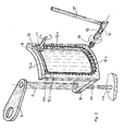
- - la figure 1 est une vue en perspective de l'appareil
- - la figure 2 est une vue qui montre le mécanisme engendrant le mouvement pour effectuer le dit transfert,
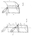
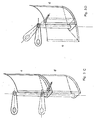
- - les figures 3A, 3B, 3C et 3D montrent les mouvements successifs du moyen qui maintient et porte les lentilles de contact,
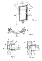
- - la figure 4A et la figure 4B montrent comment le guidage, qui assure le contact entre l'organe moteur et la partie mobile de l'appareil est effectué.
- - la figure 5A et la'figure 5B montrent l'aménagement de l'organe moteur pour assurer son contact avec la partie mobile et aussi pour le bloquer en fin de course.
- - Figure 1 is a perspective view of the apparatus
- FIG. 2 is a view which shows the mechanism generating the movement for effecting said transfer,
- FIGS. 3A, 3B, 3C and 3D show the successive movements of the means which maintains and carries the contact lenses,
- - Figure 4A and Figure 4B show how the guidance, which ensures contact between the motor member and the movable part of the device is performed.
- - Figure 5A and la'figure 5B show the arrangement of the drive member to ensure its contact with the movable part and also to block it at the end of the race.
Selon la présente invention, l'appareil stérilisateur comporte deux récipients (1) et (2) destinés à contenir respectivement la solution stérilisatrice et la solution de neutralisation, une potence (3) portant l'étui (4) renfermant les lentilles de contact.According to the present invention, the sterilizing device comprises two containers (1) and (2) intended to contain the sterilizing solution and the neutralizing solution respectively, a bracket (3) carrying the case (4) containing the contact lenses.
La dite potence est solidaire d'une glissière verticale (5) mobile en translation suivant un axe vertical et en rotation autour du même axe, et par conséquent la partie de la potence qui porte l'étui (4) effectue soit un mouvement vertical suivant une parallèle au dit axe soit un mouvement de rotation suivant un arc de cercle dont le centre se trouve sur le dit axe soit un mouvement combiné de ces deux mouvements. De préférence la potence (3) est solidaire de l'extrémité supérieure de la glissière.Said bracket is integral with a vertical slide (5) movable in translation along a vertical axis and in rotation about the same axis, and consequently the part of the bracket which carries the case (4) performs either a vertical movement according to a parallel to the said axis is a rotational movement following an arc of a circle whose center is on the said axis or a combined movement of these two movements. Preferably the gallows (3) is secured to the upper end of the slide.
La potence (3) porte un couvercle (6) adaptés aux récipients (1) et (2). L'étui (4) est fixé de manière amovible au dit couvercle de telle sorte qu'il sera contenu dans le récipient une fois que celui-ci est couvert.The bracket (3) carries a cover (6) adapted to the containers (1) and (2). The case (4) is removably attached to said cover so that it will be contained in the container once it is covered.
La dite potence est de préférence présentée horizontalement . Un perçage prés de son extrémité libre contient le couvercle (6) en suspension.Said bracket is preferably presented horizontally. A hole near its free end contains the cover (6) in suspension.
Au départ du cycle la potence (3) est en position basse, et l'étui (4) est logé dans le récipient (1) contenant la solution stérilisatrice.At the start of the cycle, the bracket (3) is in the low position, and the case (4) is housed in the container (1) containing the sterilizing solution.
Au bout d'une durée prédéterminée fixée par un mécanisme d'horlogerie ou tout autre'moyen de décompte de temps, un moyen moteur associé à ce mécanisme d'horlogerie entraîne la potence suivant un mouvement ascendant vertical, suivi par un mouvement rotatif au terme duquel l'étui (4) sera au dessus du récipient (2) et enfin suivant un mouvement descendant vertical au terme duquel l'étui (4) est immergé dans la solution de neutralisation contenue dans le récipient (2).At the end of a predetermined duration fixed by a clockwork mechanism or any other time counting means, a motor means associated with this clockwork mechanism drives the stem in a vertical upward movement, followed by a rotary movement at the end which the case (4) will be above the container (2) and finally in a vertical downward movement at the end of which the case (4) is immersed in the neutralization solution contained in the container (2).
Le moyen moteur et le mécanisme d'horlogerie sont montés dans un boitier (7).The motor means and the clock mechanism are mounted in a housing (7).
Un joint d'étanchéité est placé entre la glissière (5) et le boitier (7) d'horlogerie de telle sorte que le nettoyage de l'appareil de l'extérieur avec de l'eau n'expose pas à l'humidité le moyen moteur et le mécanisme d'horlogerie.A seal is placed between the slide (5) and the clock case (7) so that cleaning the device from the outside with water does not expose the medium motor and clockwork mechanism.
Les deux récipients (1) et (2) peuvent être fixés sur l'appareil ou pouvant être amovibles (démontables).The two containers (1) and (2) can be fixed on the device or can be removable (removable).
Sur la figure 2 on montre à titre d'exemple une réalisation de mécanisme qui peut donner une succession de mouvements formant un cycle : un mouvement vertical ascendant, un mouvement suivant un plan horizontal et enfin un mouvement vertical descendant.In Figure 2 we show by way of example an embodiment of mechanism which can give a succession of movements forming a cycle: a vertical upward movement, a movement along a horizontal plane and finally a vertical downward movement.
Ce mouvement est obtenu par le mécanisme suivant :
- Une platine (8) est cintrée autour de l'axe de la glissière (5) et solidaire avec celle-ci à l'aide d'un support (9).
- A plate (8) is curved around the axis of the slide (5) and secured to the latter by means of a support (9).
La glissière (5) est montée sur une colonne (5a) solidaire au bati(5b).The slide (5) is mounted on a column (5a) integral with the frame (5b).
Le mouvement de la platine (8) parallèlement à ou autour de l'axe de la glissière : "l'axe de la colonne (5a)" est communiqué à la potence (3) respectivement, soit sous la forme d'un même mouvement de translation, soit sous la forme d' un mouvement angulaire de même valeur que celui de la platine.The movement of the plate (8) parallel to or around the axis of the slide: "the axis of the column (5a)" is communicated to the bracket (3) respectively, either in the form of the same movement of translation, either in the form of an angular movement of the same value as that of the plate.
Une surépaisseur (10,) est ménagée sur la surface extérieure de la platine.An additional thickness (10,) is provided on the outer surface of the plate.
Un organe rotatif (11) coopère par friction ou par obstacle avec la dite surépaisseur pour animer la platine (8) suivant l'orientation donnée à la dite surépaisseur.A rotary member (11) cooperates by friction or by obstacle with said additional thickness to animate the plate (8) according to the orientation given to said additional thickness.
Pour effectuer les trois mouvements voulus - mouvement vertical ascendant,mouvement dans un plan horizontal et mouvement vertical descendant - la surépaisseur ménagée à la surface de la platine est composée d'une partie verticale descendante suivie, à son niveau inférieur d'une partie horizontale puis d'une deuxième partie verticale montante.To perform the three desired movements - vertical upward movement, movement in a horizontal plane and vertical downward movement - the extra thickness provided on the surface of the plate is composed of a vertical downward part followed, at its lower level by a horizontal part then a second vertical rising part.
Suivant une forme préférentielle de l'invention la surépaisseur (10) est une crémaillère et l'organe rotatif (11) est un pignon denté.According to a preferred form of the invention, the additional thickness (10) is a rack and the rotary member (11) is a toothed pinion.
Une rainure (12) est faite parallèlement à la crémaillère sur la même face de la platine, pour loger un doigt de guidage (13) (figure 5), ceci assure le contact entre le pignon (11) et la crémaillère (8).A groove (12) is made parallel to the rack on the same face of the plate, to accommodate a guide finger (13) (Figure 5), this ensures contact between the pinion (11) and the rack (8).
Cette rainure est composée de quatre parties : la partie (12a) parrallèle à la première partie verticale de la crémaillère pour assurer le mouvement vertical ascendant, la partie (12b) parallèle à la partie horizontale de la crémaillère pour assurer le mouvement selon un plan horizontal, la partie (12c) parallèle à la deuxième partie verticale de la crémaillère pour assurer le mouvement vertical descendant et la partie (12d) pour assurer le passage du doigt de pignon (13) de la position finale du cycle à la position initiale de celui-ci pour permettre le commencement d'un nouveau cycle.This groove is composed of four parts: the part (12a) parallel to the first vertical part of the rack to ensure the upward vertical movement, the part (12b) parallel to the horizontal part of the rack to ensure the movement along a horizontal plane , the part (12c) parallel to the second vertical part of the rack to ensure the downward vertical movement and the part (12d) to ensure the passage of the pinion finger (13) from the final position of the cycle to the initial position of that -this to allow the start of a new cycle.
La profondeur de la-partie (12d) de la rainure a la même valeur que celle de la partie (12c) au niveau de leur rencontre, par contre elle a une valeur inférieure à celle de la partie (12a) au niveau de leur rencontre,comme le montre la figure (4B), qui est une vue en coupe de la figure (4A) au niveau de la partie (12d), ceci permet un passage en continiuté de (12c) à (12d), mais une fois que le doigt (13) s'engage dans la partie (12a) il ne peut plus retourner en (12d), ceci assure un bon contact entre la crémaillère et le pignon au commencement du cycle.The depth of the part (12d) of the groove has the same value as that of the part (12c) at their meeting, on the other hand it has a value less than that of the part (12a) at their meeting , as shown in Figure (4B), which is a sectional view of Figure (4A) at the part (12d), this allows a continuous transition from (12c) to (12d), but once the finger (13) engages in the part (12a) it can no longer return to (12d), this ensures good contact between the rack and the pinion at the start of the cycle.
Les figures (3A), (3B), (3C) et (3D) représentent les étapes successives correspondant aux différents mouvements de la platine (8) et par conséquent de la potence (3).Figures (3A), (3B), (3C) and (3D) represent the successive stages corresponding to the different movements of the plate (8) and therefore of the bracket (3).
Au commencement du cycle, la platine est à la position (a) comme le montre la figure (3A), l'étui de lentilles est dans le premier récipient immergé dans la solution stérilisatrice. Au bout d'une durée prédéterminée une horloge quelconque nonAt the beginning of the cycle, the stage is in position (a) as shown in figure (3A), the lens case is in the first container immersed in the sterilizing solution. At the end of a predetermined period any clock not
présentée déclenche un mécanisme qui entraîne le pignon (11) en rotation et par conséquent la platine effectue un mouvement vertical ascendant pour prendre la position (b). A cette dernière position (b), l'étui de lentille est hors du récipient (1) mais reste toujours en regard de ce dernier.presented triggers a mechanism which drives the pinion (11) in rotation and therefore the plate performs a vertical upward movement to take position (b). In this last position (b), the lens case is outside the container (1) but always remains opposite the latter.
Le pignon (11) continue à tourner, entraînant la platine jusqu'à la position c, comme le montre figure (3B). Dans cette position la potence qui porte l'étui de lentilles est audessus du récipient (2). La figure (3C) montre la position (d) dans laquelle l'étui avec les lentilles sont immergés dans la solution de neutralisation contenue dans le récipient (2). Les lentilles restent dans ce dernier en attendant leur utilisation.The pinion (11) continues to rotate, driving the plate to position c, as shown in figure (3B). In this position the bracket carrying the lens case is above the container (2). Figure (3C) shows the position (d) in which the case with the lenses are immersed in the neutralization solution contained in the container (2). The lenses remain in the latter while awaiting their use.
La dernière partie (10a) de la crémaillère (10) correspondant à la fin du cycle n'est pas dentée. Ceci permet au pignon (11) de tourner librement pour débrancher le ressort d'entraînement au cas d'un entraînement mécanique.The last part (10a) of the rack (10) corresponding to the end of the cycle is not toothed. This allows the pinion (11) to rotate freely to disconnect the drive spring in the event of mechanical drive.
Dans le cas d'utilisation d'un moteur électrique, celui-ci sera autorisé à fonctionner pendant une période prédéterminée supérieure à celle nécessaire au transfert de l'étui d'un récipient à l'autre. La dite période, pendant laquelle le moteur est autorisé à fonctionner, prend en considération l'usure des piles d'alimentation et par conséquent l'allongement de la période de transfert. Pour commencer un autre cycle comme celui qu'on vient de décrire, on ramène la platine manuellement en actionnant la potence, à la position (a) .In the case of using an electric motor, it will be authorized to operate for a predetermined period greater than that necessary for the transfer of the case from one container to another. The said period, during which the engine is authorized to operate, takes into account the wear of the supply batteries and consequently the extension of the transfer period. To start another cycle like the one just described, the plate is returned manually by actuating the stem, to position (a).
Par sécurité et pour être sûr que l'horloge et le mécanisme d'actionnement du pignon soient mis en marche, le changement de position de la platine de la portion (c) à la position (d) sera autorisé seulement si la dite mise en marche est effectuée.For safety and to be sure that the clock and the mechanism actuation of the pinion are started, the change of position of the plate from the portion (c) to position (d) will be authorized only if said start-up is carried out.
Le but pour lequel ce changement de position est conditionné par la mise en marche de l'horloge et du mécanisme d'actionnement du pignon est d'assurer le transfert de lentilles de la solution stérilisatrice à la solution de neutralisation au bout de la durée prédéterminée.The purpose for which this change of position is conditioned by the switching on of the clock and of the pinion actuation mechanism is to ensure the transfer of lenses from the sterilizing solution to the neutralization solution at the end of the predetermined duration. .
Pour assurer, selon l'invention, l'application de telles conditions, deux réalisations sont données à titre d'exemple.To ensure, according to the invention, the application of such conditions, two embodiments are given by way of example.
Une de ces réalisations est présentée sur la figure 2, elle est constituée par une came (14) formée de deux parties, une partie fixe à travers laquelle passe un axe (15) et la deuxième partie lui est solidaire.One of these embodiments is shown in Figure 2, it is constituted by a cam (14) formed of two parts, a fixed part through which passes an axis (15) and the second part is integral with it.
Un ressort (16) pousse l'axe (15) vers la platine (8). Une fois que la platine cède la place pour effectuer ses mouvements, le dit axe avance et dépasse le niveau de la platine.A spring (16) pushes the axis (15) towards the plate (8). Once the plate gives way to make its movements, the said axis advances and exceeds the level of the plate.
Dans la position (d) de la platine, le dit axe dépasse le niveau de la platine de gauche et l'empêche de reprendre la position de départ.In position (d) of the plate, said axis exceeds the level of the left plate and prevents it from returning to the starting position.
Un levier (17) est solidaire avec l'axe (15). L'actionnement de ce levier fait tourner le dit axe et par conséquent l'éloigne de la platine. Un tel actionnement du levier peut être effectué par la même action que la mise en marche de l'horloge par exemple à l'aide du mouvement mécanique à faire pour remonter l'horloge.A lever (17) is integral with the axis (15). The actuation of this lever rotates said axis and therefore moves it away from the plate. Such actuation of the lever can be carried out by the same action as starting the clock for example using the mechanical movement to be made to wind the clock.
Le verrouillage de la platine en fin de cycle peut être encore effectué comme c'est présenté sur la figure 5. Un doigt rétractable (18) coaxial avec le pignon (11) loge, en fin de course, dans un creux (19) fait dans la platine (8). Ce doigt se retire, d'une façon classique, soit après qu'on ait remonté l'horloge, soit à l'aide d'un mécanisme quelconque pour libérer la platine.The locking of the plate at the end of the cycle can also be carried out as shown in FIG. 5. A retractable finger (18) coaxial with the pinion (11) accommodates, at the end of the race, in a hollow (19) made in the plate (8). This finger is withdrawn, in a conventional manner, either after the clock has been wound, or using any mechanism to release the plate.
Le fonctionnement de l'appareil est le suivant :
- - On place les lentilles de contact dans leur étui,
- - On place, après avoir mis l'horloge en marche, l'étui porté par la potence, dans le premier récipient contenant la solution stérilisatrice,
- - Au bout d'une durée prédéterminée, la potence effectue une série de trois mouvements: un mouvement vertical ascendant, un mouvement horizontal suivi d'un mouvement vertical descendant à la fin duquel l'étui des lentilles sera immergé dans le deuxième récipient.
- - Dans cette dernière position, la platine sera bloquée et le retour à la position de départ est seulement autorisé dans le cas où la mise en marche de l'horloge est effectuée.
- - We place the contact lenses in their case,
- - After putting the clock on, the case carried by the gallows is placed in the first container containing the sterilizing solution,
- - After a predetermined period of time, the bracket performs a series of three movements: a vertical upward movement, a horizontal movement followed by a vertical downward movement at the end of which the lens case will be immersed in the second container.
- - In this last position, the plate will be blocked and the return to the starting position is only authorized in the event that the clock is started.
Il est bien évident que la succession de mouvements de la potence décrite ci-dessus peut être effectuée avec d'autres moyens purement mécaniques, hydrauliques, électromécaniques ou d'autres moyens équivalents sans sortir du cadre du présent brevet.It is obvious that the succession of movements of the bracket described above can be carried out with other purely mechanical, hydraulic, electromechanical means or other equivalent means without departing from the scope of this patent.
Claims (11)
Priority Applications (1)
| Application Number | Priority Date | Filing Date | Title |
|---|---|---|---|
| AT86450020T ATE74525T1 (en) | 1985-09-30 | 1986-09-24 | DEVICE FOR CLEANING AND STERILIZING CONTACT LENSES. |
Applications Claiming Priority (2)
| Application Number | Priority Date | Filing Date | Title |
|---|---|---|---|
| FR8514571 | 1985-09-30 | ||
| FR8514571A FR2588097B1 (en) | 1985-09-30 | 1985-09-30 | CONTACT LENS CLEANER AND STERILIZER |
Publications (2)
| Publication Number | Publication Date |
|---|---|
| EP0218539A1 true EP0218539A1 (en) | 1987-04-15 |
| EP0218539B1 EP0218539B1 (en) | 1992-04-08 |
Family
ID=9323439
Family Applications (1)
| Application Number | Title | Priority Date | Filing Date |
|---|---|---|---|
| EP86450020A Expired - Lifetime EP0218539B1 (en) | 1985-09-30 | 1986-09-24 | Contact lenses cleaning and sterilizing apparatus |
Country Status (8)
| Country | Link |
|---|---|
| US (1) | US4816232A (en) |
| EP (1) | EP0218539B1 (en) |
| JP (1) | JPS62182712A (en) |
| AT (1) | ATE74525T1 (en) |
| CA (1) | CA1291455C (en) |
| DE (1) | DE3684751D1 (en) |
| ES (1) | ES2003360A6 (en) |
| FR (1) | FR2588097B1 (en) |
Cited By (6)
| Publication number | Priority date | Publication date | Assignee | Title |
|---|---|---|---|---|
| EP0335835A2 (en) * | 1988-03-29 | 1989-10-04 | Essilor International Compagnie Generale D'optique | Device for the sequential treatment of submerged objects and kit containing such a device |
| EP0354876A1 (en) * | 1988-08-12 | 1990-02-14 | Ciba-Geigy Ag | Contact lens disinfection unit |
| WO1990011785A1 (en) * | 1989-04-05 | 1990-10-18 | Lensmatic Ag | Device for cleaning contact lenses |
| FR2658422A1 (en) * | 1990-02-19 | 1991-08-23 | Bielsa Barrau Ste Civile | Apparatus for sterilising contact lenses |
| WO1997038733A1 (en) * | 1996-04-18 | 1997-10-23 | Charles Philip Ifejika | Apparatus for automatic cleaning of utility items |
| KR20160134366A (en) * | 2015-05-15 | 2016-11-23 | 서강대학교산학협력단 | Contact-lens cleaning apparatus |
Families Citing this family (14)
| Publication number | Priority date | Publication date | Assignee | Title |
|---|---|---|---|---|
| US5814134A (en) * | 1994-06-10 | 1998-09-29 | Johnson & Johnson Vision Products, Inc. | Apparatus and method for degassing deionized water for inspection and packaging |
| US5640980A (en) * | 1994-06-10 | 1997-06-24 | Johnson & Johnson Vision Products, Inc. | Automated apparatus for hydrating soft contact lenses |
| US5476111A (en) * | 1994-06-10 | 1995-12-19 | Johnson & Johnson Vision Products, Inc. | Apparatus for hydrating soft contact lenses |
| US5836323A (en) * | 1994-06-10 | 1998-11-17 | Johnson & Johnson Vision Products, Inc. | Automated method and apparatus for hydrating soft contact lenses |
| US5628971A (en) * | 1995-01-17 | 1997-05-13 | Norman; Geraldine U. | Apparatus for storing and sterilizing objects |
| DE19601568A1 (en) * | 1996-01-17 | 1997-07-24 | Mueller Lierheim Wolfgang G K | Method of maintaining a matching contact lens and care system therefor |
| US6289907B1 (en) * | 1999-02-04 | 2001-09-18 | Richard C. Horian | Device and method for cleaning contact lenses |
| US6619051B1 (en) * | 2002-07-12 | 2003-09-16 | Ecolab Inc. | Integrated cleaning and sanitizing system and method for ice machines |
| US20120020849A1 (en) * | 2010-07-20 | 2012-01-26 | Andrew Peter Davis | Automatic tonometer tip disinfection apparatus |
| US9360687B2 (en) | 2011-10-12 | 2016-06-07 | Yoseph Yaacobi | Contact lens cleaning systems |
| EP3125957A1 (en) | 2014-04-03 | 2017-02-08 | Novartis AG | Electrochemical system for disinfecting and cleaning contact lenses |
| JP6313867B2 (en) | 2014-04-03 | 2018-04-18 | ノバルティス アーゲー | Contact lens disinfection system |
| GB2553745B (en) * | 2016-05-08 | 2018-10-10 | Whitley Don Scient Ltd | Cleaning system and cleaning method for a stylus of an inoculation apparatus |
| CN113885226A (en) * | 2021-11-09 | 2022-01-04 | 苏州求同生物科技有限公司 | Automatic neutralization device for deep cleaning of hard orthokeratology lens |
Citations (2)
| Publication number | Priority date | Publication date | Assignee | Title |
|---|---|---|---|---|
| US4013410A (en) * | 1975-06-23 | 1977-03-22 | Ryder International Corporation | Contact lens sterilization process and apparatus |
| US4143116A (en) * | 1976-08-18 | 1979-03-06 | American Optical Corporation | Contact lens sterilizing apparatus |
Family Cites Families (9)
| Publication number | Priority date | Publication date | Assignee | Title |
|---|---|---|---|---|
| US755634A (en) * | 1903-05-27 | 1904-03-29 | Conrad Dietz | Gearing. |
| US2535110A (en) * | 1946-02-28 | 1950-12-26 | Carnegie Illinois Steel Corp | Method of heat-treating wheels |
| US2615455A (en) * | 1947-05-07 | 1952-10-28 | Persson Jonas Almer | Apparatus for cleaning watches and watch parts |
| US3837805A (en) * | 1971-01-15 | 1974-09-24 | Wave Energy Systems | Apparatus for continuous sterilization at low temperature |
| SU469469A1 (en) * | 1973-07-10 | 1975-05-05 | Всесоюзный научно-исследовательский институт горноспасательного дела | Device for sanitizing the elements of respiratory masks |
| GB1429986A (en) * | 1973-08-02 | 1976-03-31 | Lanzetter S | Machines for cleaning watch parts and other small parts of machinery |
| US4022429A (en) * | 1975-03-13 | 1977-05-10 | Daido Kiko Co., Ltd. | Lifting apparatus |
| US4381285A (en) * | 1981-01-09 | 1983-04-26 | Sidney Wittenberg | Contact lens sterilizing device |
| US4432692A (en) * | 1981-10-28 | 1984-02-21 | Woodford Manufacturing Company | Article handling apparatus |
-
1985
- 1985-09-30 FR FR8514571A patent/FR2588097B1/en not_active Expired
-
1986
- 1986-09-24 AT AT86450020T patent/ATE74525T1/en not_active IP Right Cessation
- 1986-09-24 EP EP86450020A patent/EP0218539B1/en not_active Expired - Lifetime
- 1986-09-24 DE DE8686450020T patent/DE3684751D1/en not_active Expired - Fee Related
- 1986-09-29 CA CA000519359A patent/CA1291455C/en not_active Expired - Lifetime
- 1986-09-29 US US06/912,763 patent/US4816232A/en not_active Expired - Fee Related
- 1986-09-30 ES ES8602319A patent/ES2003360A6/en not_active Expired
- 1986-09-30 JP JP61233094A patent/JPS62182712A/en active Pending
Patent Citations (2)
| Publication number | Priority date | Publication date | Assignee | Title |
|---|---|---|---|---|
| US4013410A (en) * | 1975-06-23 | 1977-03-22 | Ryder International Corporation | Contact lens sterilization process and apparatus |
| US4143116A (en) * | 1976-08-18 | 1979-03-06 | American Optical Corporation | Contact lens sterilizing apparatus |
Cited By (10)
| Publication number | Priority date | Publication date | Assignee | Title |
|---|---|---|---|---|
| EP0335835A2 (en) * | 1988-03-29 | 1989-10-04 | Essilor International Compagnie Generale D'optique | Device for the sequential treatment of submerged objects and kit containing such a device |
| EP0335835A3 (en) * | 1988-03-29 | 1990-12-27 | Essilor International Compagnie Generale D'optique | Device for the sequential treatment of submerged objects and kit containing such a device |
| EP0354876A1 (en) * | 1988-08-12 | 1990-02-14 | Ciba-Geigy Ag | Contact lens disinfection unit |
| US5059402A (en) * | 1988-08-12 | 1991-10-22 | Seamons Kenneth R | Contact lens disinfection unit |
| WO1990011785A1 (en) * | 1989-04-05 | 1990-10-18 | Lensmatic Ag | Device for cleaning contact lenses |
| US5117849A (en) * | 1989-04-05 | 1992-06-02 | Lensmatic Ag | Contact lens care system |
| FR2658422A1 (en) * | 1990-02-19 | 1991-08-23 | Bielsa Barrau Ste Civile | Apparatus for sterilising contact lenses |
| WO1997038733A1 (en) * | 1996-04-18 | 1997-10-23 | Charles Philip Ifejika | Apparatus for automatic cleaning of utility items |
| KR20160134366A (en) * | 2015-05-15 | 2016-11-23 | 서강대학교산학협력단 | Contact-lens cleaning apparatus |
| KR101687372B1 (en) | 2015-05-15 | 2016-12-16 | 서강대학교산학협력단 | Contact-lens cleaning apparatus |
Also Published As
| Publication number | Publication date |
|---|---|
| FR2588097A1 (en) | 1987-04-03 |
| ES2003360A6 (en) | 1988-11-01 |
| EP0218539B1 (en) | 1992-04-08 |
| CA1291455C (en) | 1991-10-29 |
| JPS62182712A (en) | 1987-08-11 |
| ATE74525T1 (en) | 1992-04-15 |
| DE3684751D1 (en) | 1992-05-14 |
| US4816232A (en) | 1989-03-28 |
| FR2588097B1 (en) | 1987-11-27 |
Similar Documents
| Publication | Publication Date | Title |
|---|---|---|
| EP0218539B1 (en) | Contact lenses cleaning and sterilizing apparatus | |
| EP0126665A1 (en) | Apparatus for cleaning and thermally sterilizing soft hydrophilic contact lenses | |
| WO1998011350A1 (en) | Miniature peristaltic pump | |
| FR2903586A1 (en) | APPLICATOR DISTRIBUTOR OF COSMETIC MATERIAL WITH PUSHER | |
| FR2703885A1 (en) | Hair removal device. | |
| EP0472457B1 (en) | Purging and flushing apparatus for disposable bottles containing a toxic product | |
| FR2994058A1 (en) | SEMI-AUTOMATIC CIGARETTE CONFECTIONER ON TABLE | |
| EP3897938B1 (en) | Mixing machine for manufacturing a composition from a mixture of formulations | |
| EP1782709A1 (en) | Epilating device comprising a device for cutting hairs | |
| WO2018115605A1 (en) | Application of cosmetic product, such as mascara | |
| FR2558567A1 (en) | Device for the dual mechanical control of a switch, and machine comprising its application. | |
| EP0151377A1 (en) | Device for filling cigarette paper tubes | |
| EP0293363B1 (en) | Bath tub for persons with reduced motility | |
| EP0272515A1 (en) | Battery cover for a watch case | |
| FR2700313A1 (en) | Machine for distributing, filling and closing by welding flakes intended for artificial insemination. | |
| FR2738479A1 (en) | Automatic cleaner for dentures | |
| FR2596038A1 (en) | WASHING AND STERILIZING MACHINE FOR BOTTLES | |
| FR2634243A1 (en) | STAND FOR MANEUVERING A DOOR OR SIMILAR | |
| BE1021727B1 (en) | DENTAL HYGIENE STATION. | |
| FR2753103A1 (en) | MINIATURE PERISTALTIC PUMP FOR MEDICAL USE | |
| EP3193958B1 (en) | Breast pump comprising means of rinsing a tube | |
| EP0309435B1 (en) | Electric cooking apparatus | |
| EP0466864B1 (en) | Oral hygiene device | |
| FR2721485A1 (en) | Toothbrush with mirror on back of head | |
| EP0785736A1 (en) | Bottle device with at least one associated lens-carrier attachable to a respective end of the bottle, contact lens maintainance process, and associable bottle and associable lens-carrier |
Legal Events
| Date | Code | Title | Description |
|---|---|---|---|
| PUAI | Public reference made under article 153(3) epc to a published international application that has entered the european phase |
Free format text: ORIGINAL CODE: 0009012 |
|
| AK | Designated contracting states |
Kind code of ref document: A1 Designated state(s): AT BE CH DE FR GB IT LI LU NL SE |
|
| 17P | Request for examination filed |
Effective date: 19870617 |
|
| 17Q | First examination report despatched |
Effective date: 19891116 |
|
| GRAA | (expected) grant |
Free format text: ORIGINAL CODE: 0009210 |
|
| AK | Designated contracting states |
Kind code of ref document: B1 Designated state(s): AT BE CH DE FR GB IT LI LU NL SE |
|
| PG25 | Lapsed in a contracting state [announced via postgrant information from national office to epo] |
Ref country code: AT Effective date: 19920408 |
|
| REF | Corresponds to: |
Ref document number: 74525 Country of ref document: AT Date of ref document: 19920415 Kind code of ref document: T |
|
| REF | Corresponds to: |
Ref document number: 3684751 Country of ref document: DE Date of ref document: 19920514 |
|
| ITF | It: translation for a ep patent filed |
Owner name: ORGANIZZAZIONE D'AGOSTINI |
|
| GBT | Gb: translation of ep patent filed (gb section 77(6)(a)/1977) | ||
| PG25 | Lapsed in a contracting state [announced via postgrant information from national office to epo] |
Ref country code: GB Effective date: 19920924 |
|
| PG25 | Lapsed in a contracting state [announced via postgrant information from national office to epo] |
Ref country code: SE Effective date: 19920925 |
|
| PG25 | Lapsed in a contracting state [announced via postgrant information from national office to epo] |
Ref country code: LU Free format text: LAPSE BECAUSE OF NON-PAYMENT OF DUE FEES Effective date: 19920930 Ref country code: LI Effective date: 19920930 Ref country code: CH Effective date: 19920930 Ref country code: BE Effective date: 19920930 |
|
| PLBE | No opposition filed within time limit |
Free format text: ORIGINAL CODE: 0009261 |
|
| STAA | Information on the status of an ep patent application or granted ep patent |
Free format text: STATUS: NO OPPOSITION FILED WITHIN TIME LIMIT |
|
| 26N | No opposition filed | ||
| BERE | Be: lapsed |
Owner name: BARRAU BERNARD Effective date: 19920930 |
|
| PG25 | Lapsed in a contracting state [announced via postgrant information from national office to epo] |
Ref country code: NL Effective date: 19930401 |
|
| NLV4 | Nl: lapsed or anulled due to non-payment of the annual fee | ||
| GBPC | Gb: european patent ceased through non-payment of renewal fee |
Effective date: 19920924 |
|
| PG25 | Lapsed in a contracting state [announced via postgrant information from national office to epo] |
Ref country code: FR Effective date: 19930528 |
|
| REG | Reference to a national code |
Ref country code: CH Ref legal event code: PL |
|
| PG25 | Lapsed in a contracting state [announced via postgrant information from national office to epo] |
Ref country code: DE Effective date: 19930602 |
|
| REG | Reference to a national code |
Ref country code: FR Ref legal event code: ST |
|
| EUG | Se: european patent has lapsed |
Ref document number: 86450020.2 Effective date: 19930406 |
|
| PG25 | Lapsed in a contracting state [announced via postgrant information from national office to epo] |
Ref country code: IT Free format text: LAPSE BECAUSE OF NON-PAYMENT OF DUE FEES;WARNING: LAPSES OF ITALIAN PATENTS WITH EFFECTIVE DATE BEFORE 2007 MAY HAVE OCCURRED AT ANY TIME BEFORE 2007. THE CORRECT EFFECTIVE DATE MAY BE DIFFERENT FROM THE ONE RECORDED. Effective date: 20050924 |