EP0218483A2 - Lieferwagenkarosserie - Google Patents
Lieferwagenkarosserie Download PDFInfo
- Publication number
- EP0218483A2 EP0218483A2 EP86307683A EP86307683A EP0218483A2 EP 0218483 A2 EP0218483 A2 EP 0218483A2 EP 86307683 A EP86307683 A EP 86307683A EP 86307683 A EP86307683 A EP 86307683A EP 0218483 A2 EP0218483 A2 EP 0218483A2
- Authority
- EP
- European Patent Office
- Prior art keywords
- van body
- van
- floor
- runners
- chassis
- Prior art date
- Legal status (The legal status is an assumption and is not a legal conclusion. Google has not performed a legal analysis and makes no representation as to the accuracy of the status listed.)
- Withdrawn
Links
Images





Classifications
-
- B—PERFORMING OPERATIONS; TRANSPORTING
- B62—LAND VEHICLES FOR TRAVELLING OTHERWISE THAN ON RAILS
- B62D—MOTOR VEHICLES; TRAILERS
- B62D33/00—Superstructures for load-carrying vehicles
- B62D33/04—Enclosed load compartments ; Frameworks for movable panels, tarpaulins or side curtains
-
- B—PERFORMING OPERATIONS; TRANSPORTING
- B62—LAND VEHICLES FOR TRAVELLING OTHERWISE THAN ON RAILS
- B62D—MOTOR VEHICLES; TRAILERS
- B62D33/00—Superstructures for load-carrying vehicles
- B62D33/04—Enclosed load compartments ; Frameworks for movable panels, tarpaulins or side curtains
- B62D33/048—Enclosed load compartments ; Frameworks for movable panels, tarpaulins or side curtains for refrigerated goods vehicles
Definitions
- This invention relates to van bodies and to a method of producing same.
- the present invention is especially but not exclusively applicable to vehicles or vans of 7.5 tonnes weight but may equally well be applied to a range of vehicles or vans of different weights, say, for example 16 tonnes.
- Vehicle chassis of 7.5 tonnes capacity to which the present invention may be applied include, inter alia, those manufactured by Ford, Bedford, Leyland (Roadrunner), Mercedes, MAN, Iveco, Volvo and Dodge, all of which have different wheelbases and/or chassis configurations.
- the present invention envisages ten different van body constructions but more or fewer constructions may be provided.
- Each pre-assembled van body construction according to the present invention has a front closed bulkhead, a rear bulkhead closable by either hinged doors or a movable shutter or closed by a fixed wall, a floor and a roof supported above the floor by the front and rear bulkheads, the main but by no means the only distinction between the different pre-assembled van bodies lying in the different side closure assemblies of the van bodies.
- the ten van bodies are as follows:-
- the side closure assemblies of whatever construction are connected to and/or are supported by a roof level cant rail save in the case of van body (C) where the roof is supported directly on the side closure assemblies and is capped, and by a floor level rave, both raves extending between the front and rear bulkheads.
- each body version is of bolted or rivetted construction whereby any damaged part can easily and readily be changed or whereby one body version, say a box van body, can be easily and readily converted to a different body version, say a curtainsided van body, by simply stripping off the box van body side closure assemblies and replacing them with curtain side closure assemblies, the front and rear bulkheads, floor and roof remaining the same.
- a van body according to the present invention comprises a number of welded sub-assemblies and other structural elements adapted to be releasably connected together by bolting or rivetting, preferably pop-rivetting.
- connection between sub-assemblies and/or structural elements is easily effected by skimming or shaving off the heads of the pop rivets and pushing out the rivet stems.
- a feature of the present invention is that the front and rear bulkheads are welded sub-assemblies common to all ten body versions.
- Another sub-assembly common to all ten body versions is the floor sub-frame of bolted and rivetted construction, which sub-assembly takes into account variations in different vehicle chassis and wheelbases.
- Another aspect of the present invention is therefore a kit of parts for assembling a van body by bolting and/or rivetting the parts together, the parts comprising welded sub-assemblies, structural elements and side closure assemblies.
- the kit of parts includes a combination of welded sub-assemblies and structural elements from which more than one construction of van body can be assembled.
- the kit of parts contains welded sub-assemblies and structural elements permitting assembly of any one of the aforesaid ten body versions therefrom.
- a body version may have two different side closure assemblies, one on each side. For example, a fixed closed wall on one side and a curtain on the other side.
- the method of producing a van body version according to the present invention comprises assembling the required body version on the workshop or factory floor, bringing the vehicle chassis into the factory, adapting the latter to provide a coupling interface with the floor assembly of the body version, mounting the body version on the adapted chassis, and bolting and/or rivetting them together.
- the basic chassis can be converted into a van with a specific body version as called for by the customer normally within one day or less.
- the body version is assembled using jigs from the welded sub-assemblies, structural elements and side closure assemblies taken from stock or stores.
- a 7.5 tonne vehicle (Fig. 1) comprises a vehicle chassis 40 with driving cab 41 and a van body 42 according to the invention mounted on the chassis 40.
- the van body 42 is of bolted and/or rivetted GRP plywood or aluminium construction and can be any one of the versions A to J hereinbefore listed bearing in mind that one version can have two different side closure assemblies if specified by the customer.
- the van body 42 (see Fig. 2) comprises a floor F, a roof R, a front bulkhead FB and a rear bulkhead RB, the two bulkheads FB and RB supporting the roof R above the floor F and providing a basic open-sided van body whereof the sides can be closed by different side closure assemblies as previously specified.
- a fixed wall 42 namely a solid multi-ply, GRP-coated side wall (body version A); an insulated fixed wall 43, namely a multi-ply, GRP coated sandwich with an infill a highly rated plastics foam (body version C); a curtain side assembly 44 incorporating vertical tensioning straps and buckles 45 and capable of being horizontally tensioned in the closed condition (body version E); a combined curtain/door (panel) side assembly 46 comprising two rigid end panels 47 of GRP-coated multi-ply connected to an intermediate curtain 48 (body version H); and a sliding door side assembly 49 comprising sliding doors 50, for example four (body version I).
- one version of a van body according to the present invention can be readily changed to another version simply by removing the side closure- assemblies and substituting others to suit the customers requirements.
- the rear bulkhead can be closed by hinged doors 51, a vertically sliding shutter 52, or a solid fixed wall (not shown) if the van body has side access.
- each basic body version A, E, H, I has a chilled and/or a refrigerated version, and it will be manifest that a side closure assembly of a basic body version would not be replaced by the equivalent chilled or refrigerated side assembly. More specifically there can be interchange between basic body version side closure assemblies, chilled body version side closure assemblies, or refrigerated body version side closure assemblies.
- the preferred method of manufacturing a van body according to the present invention is effected in two distinct stages, namely manufacture of the van body version required by the customer, and adaptation of the chassis to receive the pre-assembled van body version followed by mounting of the latter on the adapted chassis and bolting and/or rivetting of the two together. It will be manifest that the van body version and chassis can subsequently be additionally coupled together by welding or other conventional securing means if considered necessary or desirable.
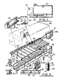
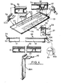
- Each van body version comprises a bolted or rivetted floor sub-assembly (Fig. 3), a welded rear bulkhead sub-assembly (Fig. 5), a welded front bulkhead sub-assembly (Fig. 6) and a roof (Fig. 4), all bolted and/or welded, preferably pop-welded, together to define an open-sided van body to which selected side closure assemblies can be bolted and/or rivetted, the assembled van body then being located on the adapted chassis and the two are bolted and/or rivetted together.
- the preparation work on the chassis is for the purpose of ensuring that the common floor sub-assembly will be accepted by any of the chassis versions and with this in mind a bolt-receiving hole and/or slot connecting interface is provided.
- a bolt-receiving hole and/or slot connecting interface is provided.
- transversely- extending slots are provided in transverse bearers of the floor sub-assembly and holes are formed in runners 54 which are connected, by bolting, to the existing frame members 53 of the chassis.
- chassis frame members 53 It may be necessary with some chassis versions to extend the frame members 53 and, if so, channel configuration extensions 53A are bolted to the rear end of the chassis frame members 53. Brackets (not shown) may be bolted to the extended chassis frame members 53A, if necessary to mount underrun bars.
- the adaptation runners 54 are of channel configuration with an extension tail 54A.
- the runners 54 can either be directly bolted onto the chassis frame members 53 or, to comply with chassis manufacturers (such as Ford) requirements indirectly by an angle bracket 55 bolted to the chassis runner member 53 and the extension tail 54A or by a flat bracket 55A where the extension tail 54A is interrupted as indicated at 54A1 as occurs at the rear wheel region of the vehicle chassis.
- the floor sub-assembly comprises bearers 56, and at spaced intervals across each bearer 56 is a grouping of two slots 56A, 56B adapted to receive bolts to connect the bearer 56 to each of the runners . 54, i.e. the aforesaid interface.
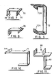
- Each bearer 56 (see Fig. 7) is generally of J-configuration and at each end within the channel there is rivetted a right-angle bracket 57 formed with a bolt hole 57A.
- the bearers 56 are bolted at each end via the plate 57 and bolt hole 57A into the channel of a channel configuration rave rail 58 (see Fig. 8) which has an upward extension 58A which with the upper flange of the channel provides a locating seating along the edges of the floor sub-assembly for a one-piece floor 59.
- the brackets 57 are designed to ensure that the ends of the bearers 56 precisely match the inside faces of the rave rail 58 consequently ensuring precision mounting of the one-piece floor 59.
- the bearers 56 are of short length to leave two wells for the wheels and are bolted to a pair of inverted angle members 60 having at two spaced intervals a locating step 61.
- An adjustable bearer 62 is bolted between the angle member 60 and the rave 58, its position (one of two) being determined by the wheelbase of the vehicle chassis.
- a stiffener 63 of I-configuration having at corresponding two spaced intervals a locating step 64.
- the adjustable bearer 62 (one for each side) is of channel configuration having within its channel at the angle member 60 end a plate (not shown) whereby it can be bolted to the angle member 60, and at its rave 58 end a plate 65 with an open-ended elongate slot 66 through which the adjustable bearer 62 can be bolted to the stiffener 63 as indicated at 67.
- the steps 61 and 64 simply serve to locate the adjustable bearer 62.
- the stiffener 63 has lateral right-angled wings or flanges 68 permitting it to be bolted within adjacent full width bearers 56.
- the above construction substantially strengthens the floor sub-assembly in the region of the wheelarches where otherwise it would be weakened by the provisions of the wells.
- the abovedescribed floor sub-assembly is common to all versions of van body.
- the rear bulkhead assembly (Fig. 5) is of welded construction and is also common to all versions of van body. It consists of two side pillars 70 of square tubular section, a bottom bearer 71 and a header 72 which are welded together.
- the bottom bearer 71 of channel configuration opens to the front of the van body with its longer limb uppermost and welded within the channel are stiffeners 73, fixing brackets 74 and slotted angle support pads 75.
- Location plates 76 are provided at each end of the side members 70 at the bottom bearer 71.
- the header 72 is also of channel section open to the front of the van body and each limb has an inwardly-directed extension 72A.
- the inner end of the upper limb of the bottom bearer 71 has an upstand 71A to define with the upper limb a seating for the one-piece floor 59.
- the rear bulkhead sub-assembly is bolted onto the rear end of the floor sub-assembly via the fixing brackets 74 and the support pads 75.
- the rear bulkhead may be closed either by hinged doors 51 or a vertically movable shutter 52.
- the pillars 70 are drilled as indicated at 70A to accept door hinges when the rear bulkhead is to be closed by hinged doors.
- the front bulkhead sub-assembly (Fig. 6) is of welded construction and is common to all body versions. It comprises two side pillars 76 of rectangular cross-section, a bottom bearer 80 and a header 81. It has two fixing brackets 82 with associated slotted angled support pads 83 welded within the channel of the bottom bearer 80.
- the bottom bearer 80 and the header 81 are also joined by two channel inner posts 85 and these are joined together and to the side member by cross channel members 86 and 87 respectively.
- the bottom bearer 80 has an upwardly open channel 88 and the header 81 has a downwardly-open channel 89 with an inwardly-directed flange 90.
- These channels 88 and 89 with the channels in the inner posts 85 and channel members 86, 86 serve to assist in mounting front wall panels.
- the front bulkhead is bolted onto the front end of the floor sub-assembly via the fixing brackets 82 and slotted support pads 83.
- the roof 59 is, in this example, of one-piece construction moulded from glass reinforced plastic (GRP) and has a slight downwards run towards its lateral edges (see detail 59A).
- the roof 59 may have two groups of fore-and-aft rainwater control ridges 90 with the roof having a slight rundown from the ends of the latter to the adjacent roof end.
- the ridges 90 serve additionally to stiffen the one-piece roof.
- the roof 59 is carried on a welded aluminium frame 91 of channel section incorporating roof support strings 92 of top-hat section to which the roof 59 is bolted, which frame 91 is bolted onto the front and rear headers 81, 72 of the front and rear bulkheads.
- a roof edge channel 93 which has a lower flange 93A which engages under the frame 91 and an upper outwardly-directed flange 93B on which the roof 59 rests. Securement is by bolting.
- a rain gutter 94 is fixed along each lateral edge of the roof 59 by bolting and adhesive strips 95. This gutter is for basic van body versions.
- a rain gutter 96 which is essentially the same as rain gutter 94 save that it has a longer depending limb 96A than the depending limb 94A of the gutter 94 to accommodate the increased thickness of roof resulting from the insulation necessary in both cases.
- a rain gutter 97 of C-section Adjacent the gutter 97 is a channel 98 in the roof 59, which channel opens into the rear vertical pillars 70 down which rainwater flow (see Fig. 1) for disposal and the rear and bottom of the van body.
- Fig. 17 shows a plastics moulded bow front 100 of one-piece construction serving to reduce wind resistance. This is a component which is common to all versions of the van body save those where a chiller unit or refrigerator unit is provided, and presents an uninterrupted surface at the front of the van body. This is bolted at its rear to a structural element 101 associated with the front bulkhead.
- the side closure assemblies are, it will be appreciated, readily assembled on and removable from the van body carcass constituted by floor, roof and front and rear bulkheads since they are fitted and secured by bolting and/or rivetting and possibly adhesives or other readily releasable securement.
- a side closure assembly will comprise a top or cant rail, a bottom rail or rave, an upper track in the case of a curtain side closure assembly and a combined curtain/panel or door side closure assembly, and upper and lower tracks in the case of sliding door closure assemblies.
- these structural elements are designed to be common to all or as many van body versions as possible.
- trims and capping elements are provided to cover and conceal joints and again where possible these are designed to be common to as many van body versions as possible.
- Fig. 14 there is shown the upper and lower ends of a box van version.
- the side closure assembly is a GRP-coated multi-ply wall 42 spaced from the rave 58 by wooden battens or stringers 110 and supported on a bottom rail 111 bolted to the rave 58.
- a rubbing rail 112 finishes off and seals the bottom of the side closure assembly.
- the top of the box van body side assembly is substantially as described with reference to Fig. 4, the wall 42 being bolted for support to a top rail 113 which caps and seals the wall.
- FIGs. 15 and 16 there is shown details of a curtain side closure assembly namely an upper track 114 secured to a top rail 115, a curtain 116, rollers 117 and valance 118. At floor level is a rave 119 onto which the curtain strap hooks 120 can be engaged.
- the curtain 116 has two end poles 121, 122 housed in two open pillars defined by structural elements 123, 124 and 125.
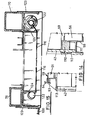
- Fig. 12 there is illustrated details of a refrigerated van body where it can be seen that the floor 59 side walls 43 and doors 51 are provided with high duty foam plastics infills 126.
- the doors 51 have around their edges double flexible channel sealing elements 127 providing a labyrinthal sealing structure.
- the insulation is such that the refrigerated van body merits an ATP certificate type C.
- a cooler or refrigerator unit is mounted on the front bulkhead in these non-basic van body versions.
- the doors 51 are mounted by means of a novel hinge 128 having a forked member 129 connected with the door 51 and rotatable about a hinge pin 129 connected to the vertical pillar 70 of the rear bulkhead, the bearings 130 of the hinge being at the ends of the pin 129 so that loads on the hinge are considerably reduced and there is uniform wear.
- a rear step 130 is provided on the various van body versions and the rear lamps and number plate are mounted above same at 131.
- curtainsided closure assemblies examples of curtainsided closure assemblies, insulated curtainsided closure assemblies and curtain/panel or door side closure assemblies can be seen in United Kingdom Patents 1262879, 2106166 and 2106573 respectively.
Landscapes
- Engineering & Computer Science (AREA)
- Chemical & Material Sciences (AREA)
- Combustion & Propulsion (AREA)
- Transportation (AREA)
- Mechanical Engineering (AREA)
- Physics & Mathematics (AREA)
- Thermal Sciences (AREA)
- Refrigerator Housings (AREA)
- Body Structure For Vehicles (AREA)
Applications Claiming Priority (2)
| Application Number | Priority Date | Filing Date | Title |
|---|---|---|---|
| GB8524537 | 1985-10-04 | ||
| GB858524537A GB8524537D0 (en) | 1985-10-04 | 1985-10-04 | Van bodies |
Publications (2)
| Publication Number | Publication Date |
|---|---|
| EP0218483A2 true EP0218483A2 (de) | 1987-04-15 |
| EP0218483A3 EP0218483A3 (de) | 1989-02-22 |
Family
ID=10586206
Family Applications (1)
| Application Number | Title | Priority Date | Filing Date |
|---|---|---|---|
| EP86307683A Withdrawn EP0218483A3 (de) | 1985-10-04 | 1986-10-03 | Lieferwagenkarosserie |
Country Status (2)
| Country | Link |
|---|---|
| EP (1) | EP0218483A3 (de) |
| GB (1) | GB8524537D0 (de) |
Cited By (8)
| Publication number | Priority date | Publication date | Assignee | Title |
|---|---|---|---|---|
| EP0466588A1 (de) * | 1990-07-11 | 1992-01-15 | E C P Etudes Realisations Constructions Amenagements Polyester | Zerlegbare isothermische Zelle für Lieferwagen |
| AU631047B2 (en) * | 1990-02-22 | 1992-11-12 | Krueger Transport Equipment Pty Ltd | Curtain sided trailers |
| EP0978443A3 (de) * | 1998-08-06 | 2000-04-26 | FURGOCAR - S.r.L. | Verfahren und Vorrichtung zum Bau eines viereckigen Rahmens für wärmeisolierende Lastkraftwagenaufbauten |
| DE20018314U1 (de) * | 2000-10-26 | 2002-03-28 | Fahrtec Systeme GmbH, 17034 Neubrandenburg | Koffermodul für Kraftfahrzeuge |
| WO2010017754A1 (zh) * | 2008-08-09 | 2010-02-18 | Bai Shiliang | 智能型组装式车厢多用途车 |
| CN109353415A (zh) * | 2018-09-30 | 2019-02-19 | 苏州安耐驰汽车科技有限公司 | 一种货车厢体的车厢架 |
| CN109436101A (zh) * | 2018-11-26 | 2019-03-08 | 镇江飞驰汽车集团有限责任公司 | 一种冷藏车新型厢体结构 |
| CN115158492A (zh) * | 2022-07-14 | 2022-10-11 | 四川蔚瓴轻量化汽车工业有限公司 | 一种轻量化全铝厢式防水车厢 |
Family Cites Families (7)
| Publication number | Priority date | Publication date | Assignee | Title |
|---|---|---|---|---|
| GB739400A (en) * | 1953-10-15 | 1955-10-26 | Southern Forge Ltd | Improvements relating to metal floors |
| GB1021257A (en) * | 1961-10-27 | 1966-03-02 | Bowyer Bros Congleton Ltd | Improvements relating to vehicle bodies |
| DK106900A (de) * | 1962-12-27 | |||
| US3724526A (en) * | 1971-12-16 | 1973-04-03 | C Huprich | Insulated overhead door for trucks and the like |
| SE362495B (de) * | 1971-12-30 | 1973-12-10 | Igloo Flex Ab | |
| GB1566279A (en) * | 1976-07-19 | 1980-04-30 | David Ltd L | Transportable freight containers |
| GB2106166B (en) * | 1981-05-30 | 1985-01-16 | Boalloy Ltd | Insulated van bodies |
-
1985
- 1985-10-04 GB GB858524537A patent/GB8524537D0/en active Pending
-
1986
- 1986-10-03 EP EP86307683A patent/EP0218483A3/de not_active Withdrawn
Cited By (9)
| Publication number | Priority date | Publication date | Assignee | Title |
|---|---|---|---|---|
| AU631047B2 (en) * | 1990-02-22 | 1992-11-12 | Krueger Transport Equipment Pty Ltd | Curtain sided trailers |
| EP0466588A1 (de) * | 1990-07-11 | 1992-01-15 | E C P Etudes Realisations Constructions Amenagements Polyester | Zerlegbare isothermische Zelle für Lieferwagen |
| FR2664546A1 (fr) * | 1990-07-11 | 1992-01-17 | Lebrequier Marcel | Cellule isotherme demontable pour fourgonnette. |
| EP0978443A3 (de) * | 1998-08-06 | 2000-04-26 | FURGOCAR - S.r.L. | Verfahren und Vorrichtung zum Bau eines viereckigen Rahmens für wärmeisolierende Lastkraftwagenaufbauten |
| DE20018314U1 (de) * | 2000-10-26 | 2002-03-28 | Fahrtec Systeme GmbH, 17034 Neubrandenburg | Koffermodul für Kraftfahrzeuge |
| WO2010017754A1 (zh) * | 2008-08-09 | 2010-02-18 | Bai Shiliang | 智能型组装式车厢多用途车 |
| CN109353415A (zh) * | 2018-09-30 | 2019-02-19 | 苏州安耐驰汽车科技有限公司 | 一种货车厢体的车厢架 |
| CN109436101A (zh) * | 2018-11-26 | 2019-03-08 | 镇江飞驰汽车集团有限责任公司 | 一种冷藏车新型厢体结构 |
| CN115158492A (zh) * | 2022-07-14 | 2022-10-11 | 四川蔚瓴轻量化汽车工业有限公司 | 一种轻量化全铝厢式防水车厢 |
Also Published As
| Publication number | Publication date |
|---|---|
| GB8524537D0 (en) | 1985-11-06 |
| EP0218483A3 (de) | 1989-02-22 |
Similar Documents
| Publication | Publication Date | Title |
|---|---|---|
| US8991896B1 (en) | Collapsible hard top for sport utility vehicle | |
| US5018781A (en) | Roof structure for modular vehicle body and method of building same | |
| US5066067A (en) | Prefabricated bus housing | |
| EP0807566B1 (de) | Lastbodenstruktur eines Kraftfahrzeuges | |
| US6652018B2 (en) | Trailer with side wall having laminate panel | |
| CA2203370C (en) | A method of manufacturing a motor vehicle | |
| CA2956218C (en) | Cargo body and method of assembling the same | |
| US5131714A (en) | General delivery load carrying vehicle | |
| US5286081A (en) | Panel cab | |
| JP4106100B2 (ja) | 陸上車輛または鉄道車輛およびその組み立て方法 | |
| US20030168880A1 (en) | Sectional removably attachable top | |
| US6561572B1 (en) | Cab enclosure construction | |
| US7216911B2 (en) | Motor vehicle rear module | |
| US6267434B1 (en) | Multi-purpose fairing | |
| US6793271B1 (en) | Transparent Shipping Container | |
| US20010035667A1 (en) | Universal rear door frame for a trailer | |
| EP1459964B1 (de) | Verfahren zum Zusammenbauen von Kraftfahrzeugkarosserie mit Türen, gemäss des Verfahrens hergstellten Kraftfahrzeugkarosserie und Türen für solche Kraftfahrzeugkarosserie | |
| US6676203B2 (en) | Vehicle roof | |
| US11220299B2 (en) | Modular loading platform for a vehicle | |
| US6921077B1 (en) | Roof top for vehicles | |
| EP0482563B1 (de) | Modulares Fahrzeug | |
| GB2107258A (en) | Vehicle bodies | |
| CA3085251A1 (en) | Aftermarket door assembly for extended semi-truck cab | |
| CA2182312A1 (en) | Vehicle body | |
| DE202022001593U1 (de) | Mehrspuriges Lastentransportfahrzeug |
Legal Events
| Date | Code | Title | Description |
|---|---|---|---|
| PUAI | Public reference made under article 153(3) epc to a published international application that has entered the european phase |
Free format text: ORIGINAL CODE: 0009012 |
|
| AK | Designated contracting states |
Kind code of ref document: A2 Designated state(s): DE ES FR GB NL |
|
| PUAL | Search report despatched |
Free format text: ORIGINAL CODE: 0009013 |
|
| AK | Designated contracting states |
Kind code of ref document: A3 Designated state(s): DE ES FR GB NL |
|
| STAA | Information on the status of an ep patent application or granted ep patent |
Free format text: STATUS: THE APPLICATION IS DEEMED TO BE WITHDRAWN |
|
| 18D | Application deemed to be withdrawn |
Effective date: 19890823 |
|
| RIN1 | Information on inventor provided before grant (corrected) |
Inventor name: BROADBENT, EDWARD GERALD |