EP0218144B1 - Injektions-Spritzpistole mit einstellbarer Druckbegrenzung - Google Patents
Injektions-Spritzpistole mit einstellbarer Druckbegrenzung Download PDFInfo
- Publication number
- EP0218144B1 EP0218144B1 EP86113143A EP86113143A EP0218144B1 EP 0218144 B1 EP0218144 B1 EP 0218144B1 EP 86113143 A EP86113143 A EP 86113143A EP 86113143 A EP86113143 A EP 86113143A EP 0218144 B1 EP0218144 B1 EP 0218144B1
- Authority
- EP
- European Patent Office
- Prior art keywords
- handle
- lever
- operating lever
- arm
- spring element
- Prior art date
- Legal status (The legal status is an assumption and is not a legal conclusion. Google has not performed a legal analysis and makes no representation as to the accuracy of the status listed.)
- Expired - Lifetime
Links
Images
Classifications
-
- B—PERFORMING OPERATIONS; TRANSPORTING
- B05—SPRAYING OR ATOMISING IN GENERAL; APPLYING FLUENT MATERIALS TO SURFACES, IN GENERAL
- B05B—SPRAYING APPARATUS; ATOMISING APPARATUS; NOZZLES
- B05B12/00—Arrangements for controlling delivery; Arrangements for controlling the spray area
- B05B12/002—Manually-actuated controlling means, e.g. push buttons, levers or triggers
-
- A—HUMAN NECESSITIES
- A61—MEDICAL OR VETERINARY SCIENCE; HYGIENE
- A61M—DEVICES FOR INTRODUCING MEDIA INTO, OR ONTO, THE BODY; DEVICES FOR TRANSDUCING BODY MEDIA OR FOR TAKING MEDIA FROM THE BODY; DEVICES FOR PRODUCING OR ENDING SLEEP OR STUPOR
- A61M5/00—Devices for bringing media into the body in a subcutaneous, intra-vascular or intramuscular way; Accessories therefor, e.g. filling or cleaning devices, arm-rests
- A61M5/178—Syringes
- A61M5/31—Details
- A61M5/315—Pistons; Piston-rods; Guiding, blocking or restricting the movement of the rod or piston; Appliances on the rod for facilitating dosing ; Dosing mechanisms
- A61M5/31565—Administration mechanisms, i.e. constructional features, modes of administering a dose
- A61M5/3159—Dose expelling manners
- A61M5/31593—Multi-dose, i.e. individually set dose repeatedly administered from the same medicament reservoir
- A61M5/31595—Pre-defined multi-dose administration by repeated overcoming of means blocking the free advancing movement of piston rod, e.g. by tearing or de-blocking
-
- A—HUMAN NECESSITIES
- A61—MEDICAL OR VETERINARY SCIENCE; HYGIENE
- A61M—DEVICES FOR INTRODUCING MEDIA INTO, OR ONTO, THE BODY; DEVICES FOR TRANSDUCING BODY MEDIA OR FOR TAKING MEDIA FROM THE BODY; DEVICES FOR PRODUCING OR ENDING SLEEP OR STUPOR
- A61M5/00—Devices for bringing media into the body in a subcutaneous, intra-vascular or intramuscular way; Accessories therefor, e.g. filling or cleaning devices, arm-rests
- A61M5/48—Devices for bringing media into the body in a subcutaneous, intra-vascular or intramuscular way; Accessories therefor, e.g. filling or cleaning devices, arm-rests having means for varying, regulating, indicating or limiting injection pressure
- A61M5/488—Limiting injection pressure
-
- B—PERFORMING OPERATIONS; TRANSPORTING
- B05—SPRAYING OR ATOMISING IN GENERAL; APPLYING FLUENT MATERIALS TO SURFACES, IN GENERAL
- B05B—SPRAYING APPARATUS; ATOMISING APPARATUS; NOZZLES
- B05B12/00—Arrangements for controlling delivery; Arrangements for controlling the spray area
- B05B12/002—Manually-actuated controlling means, e.g. push buttons, levers or triggers
- B05B12/0022—Manually-actuated controlling means, e.g. push buttons, levers or triggers associated with means for restricting their movement
- B05B12/0024—Manually-actuated controlling means, e.g. push buttons, levers or triggers associated with means for restricting their movement to a single position
- B05B12/0026—Manually-actuated controlling means, e.g. push buttons, levers or triggers associated with means for restricting their movement to a single position to inhibit delivery
-
- A—HUMAN NECESSITIES
- A61—MEDICAL OR VETERINARY SCIENCE; HYGIENE
- A61M—DEVICES FOR INTRODUCING MEDIA INTO, OR ONTO, THE BODY; DEVICES FOR TRANSDUCING BODY MEDIA OR FOR TAKING MEDIA FROM THE BODY; DEVICES FOR PRODUCING OR ENDING SLEEP OR STUPOR
- A61M5/00—Devices for bringing media into the body in a subcutaneous, intra-vascular or intramuscular way; Accessories therefor, e.g. filling or cleaning devices, arm-rests
- A61M5/178—Syringes
- A61M5/24—Ampoule syringes, i.e. syringes with needle for use in combination with replaceable ampoules or carpules, e.g. automatic
-
- A—HUMAN NECESSITIES
- A61—MEDICAL OR VETERINARY SCIENCE; HYGIENE
- A61M—DEVICES FOR INTRODUCING MEDIA INTO, OR ONTO, THE BODY; DEVICES FOR TRANSDUCING BODY MEDIA OR FOR TAKING MEDIA FROM THE BODY; DEVICES FOR PRODUCING OR ENDING SLEEP OR STUPOR
- A61M5/00—Devices for bringing media into the body in a subcutaneous, intra-vascular or intramuscular way; Accessories therefor, e.g. filling or cleaning devices, arm-rests
- A61M5/178—Syringes
- A61M5/31—Details
- A61M5/315—Pistons; Piston-rods; Guiding, blocking or restricting the movement of the rod or piston; Appliances on the rod for facilitating dosing ; Dosing mechanisms
- A61M5/31533—Dosing mechanisms, i.e. setting a dose
- A61M5/31545—Setting modes for dosing
- A61M5/31548—Mechanically operated dose setting member
- A61M5/3156—Mechanically operated dose setting member using volume steps only adjustable in discrete intervals, i.e. individually distinct intervals
-
- A—HUMAN NECESSITIES
- A61—MEDICAL OR VETERINARY SCIENCE; HYGIENE
- A61M—DEVICES FOR INTRODUCING MEDIA INTO, OR ONTO, THE BODY; DEVICES FOR TRANSDUCING BODY MEDIA OR FOR TAKING MEDIA FROM THE BODY; DEVICES FOR PRODUCING OR ENDING SLEEP OR STUPOR
- A61M5/00—Devices for bringing media into the body in a subcutaneous, intra-vascular or intramuscular way; Accessories therefor, e.g. filling or cleaning devices, arm-rests
- A61M5/178—Syringes
- A61M5/31—Details
- A61M5/315—Pistons; Piston-rods; Guiding, blocking or restricting the movement of the rod or piston; Appliances on the rod for facilitating dosing ; Dosing mechanisms
- A61M5/31565—Administration mechanisms, i.e. constructional features, modes of administering a dose
- A61M5/31576—Constructional features or modes of drive mechanisms for piston rods
- A61M5/31578—Constructional features or modes of drive mechanisms for piston rods based on axial translation, i.e. components directly operatively associated and axially moved with plunger rod
- A61M5/31581—Constructional features or modes of drive mechanisms for piston rods based on axial translation, i.e. components directly operatively associated and axially moved with plunger rod performed by rotationally moving or pivoting actuator operated by user, e.g. an injection lever or handle
Definitions
- the invention relates to an injection spray gun with a bracket designed for the attachment of a sleeve provided for receiving a cylinder ampoule, a handle connected to it and a pivotally attached operating lever and a guide guided in the bracket and connected to the operating lever, the displacement of a push rod in the cylinder ampoule causing the push rod.
- Injection spray guns of this type are used in a wide variety of medical fields, in particular also by dentists for intraligamentary anesthesia.
- the advantage of such spray guns is that they can be used to generate a relatively high pressure for individual spraying processes.
- the object of the invention is therefore to design the known injection spray gun so that the pressure exerted by the lever mechanism on the liquid to be sprayed can be limited and even adjusted and regulated.
- a pressure limiting device acting on the operating lever and push rod is provided with a spring element and a two-armed bell crank, the operating lever being attached to the handle with the interposition of the two-armed bell crank, the two-armed bell crank on an axis arranged in the handle is pivotally mounted and the operating lever is pivotally attached with its axis of rotation to the first arm of the bell crank and the spring element engages the second arm of the bell crank.
- the deflection lever has the function of an abutment for the operating lever, which abutment can evade the pressure caused by the operating lever when a certain size is reached and can return to the starting position when this pressure is released.
- the spring element forms the adjustable abutment force.
- the spring element is advantageously designed as a spiral spring and arranged on a guide rod, this guide rod being articulated with its first end on the second arm of the deflection lever and protruding with its second end into an adjusting screw inserted in the handle and the lower end of the spring element on the edge of the set screw.
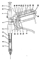
- the injection spray gun illustrated in the drawing consists essentially of a handle 1, a bracket 2 formed integrally therewith and a control lever 3 which is pivotally mounted in the handle and which actuates a pawl 4 via a lever mechanism which is installed in the handle and is explained in more detail below again engages in notches 6 formed on the push rod 5 and causes the push rod 5 to be advanced after the operating lever 3 has been actuated.
- the push rod 5 is guided in the holder 2 and in an additional guide piece 7 on the handle 1.
- a sleeve 8 is inserted into the holder 2, in which a cylindrical ampoule 9 containing the medicament to be injected is inserted with a piston 10 closing it off to the outside.
- the end of the push rod 5 on the sleeve side comes into contact with the piston 10 and presses the piston into the cylinder ampoule during the spraying process.
- the operating lever 3 is not rotatably mounted with its axis of rotation 11 directly in the handle 1, but rather on the first arm 12 of a two-armed deflection lever 13, which in turn is fastened in the handle 1 rotatably about an axis 14.
- the upper end 16 of a guide rod 17 is rotatably fastened via the axis 18, the lower end 19 of the guide rod 17 protruding into an adjusting screw 20 designed as a hollow body, which in turn is inserted in the handle 1 so as to be adjustable in length .
- a spring element 21 Arranged on the guide rod 17 is a spring element 21 designed as a spiral spring, which comes into contact with its lower end 22 against the edge 23 of the adjusting screw 20 and with its upper end 24 abuts a sleeve 25 arranged on the guide rod 17.
- the doctor actuating the injection gun during an injection moves the operating lever 3 against the handle 1, the operating lever 3 rotating about the axis of rotation 11 and the pawl 4 together with the push rod 5 moving against the piston 10.
- this pressure-regulated lever mechanism ensures that the cylinder ampoule can no longer burst due to excessive pressure, and on the other hand that, in particular, paradontical teeth cannot be removed from their tooth bed during intraligamental injection.
Landscapes
- Health & Medical Sciences (AREA)
- Vascular Medicine (AREA)
- Engineering & Computer Science (AREA)
- Anesthesiology (AREA)
- Biomedical Technology (AREA)
- Heart & Thoracic Surgery (AREA)
- Hematology (AREA)
- Life Sciences & Earth Sciences (AREA)
- Animal Behavior & Ethology (AREA)
- General Health & Medical Sciences (AREA)
- Public Health (AREA)
- Veterinary Medicine (AREA)
- Infusion, Injection, And Reservoir Apparatuses (AREA)
- Nozzles (AREA)
- Reciprocating Pumps (AREA)
- Dental Tools And Instruments Or Auxiliary Dental Instruments (AREA)
Description
- Die Erfindung betrifft eine Injektions-Spritzpistole mit einer, für den Ansatz einer für die Aufnahme einer Zylinderampulle vorgesehenen Hülse ausgebildeten Halterung, einem mit dieser verbundenen Handgriff und einem daran schwenkbar befestigten Bedienungshebel und einer, in der Halterung geführten und mit dem Bedienungshebel verbundenen, die Verschiebung eines in der Zylinderampulle befindlichen Kolbens bewirkende Druckstange.
- Solche Injektions-Spritzpistolen werden in vielfältigen medizinischen Bereichen angewandt, insbesondere auch von Zahnärzten für die intraligamentale Anästhesie. Vorteil solcher Spritzpistolen ist, dass mit ihnen ein verhältnismässig hoher Druck für einzelne Spritzvorgänge erzeugt werden kann.
- Nachteilig ist aber andererseits bei solchen Injektions-Spritzpistolen, dass der das Instrument bedienende Arzt den erzeugten Druck rein gefühlsmässig kontrollieren bzw. begrenzen muss, um beispielsweise zu verhindern, dass nicht etwa einerseits die eingesetzte Zylinderampulle mit der zu spritzenden Lösung birst oder andererseits ein zu behandelnder Zahn aus seinem paradontösen Zahnbett herausgelöst bzw. zumindest gelockert wird.
- Aufgabe der Erfindung ist es deshalb, die bekannte Injektions-Spritzpistole so auszubilden, daß der von der Hebelmechanik auf die zu spritzende Flüssigkeit ausgeübte Druck begrenzt und sogar eingestellt und reguliert werden kann.
- Diese Aufgabe wird dadurch gelöst, daß bei einer Injektions-Spritzpistole der eingangs genannten Art eine, auf Bedienungshebel und Druckstange einwirkende Druckbegrenzungsvorrichtung mit einem Federelement und einem zweiarmigen Umlenkhebel vorgesehen ist, wobei der Bedienungshebel unter Zwischenschaltung des zweiarmigen Umlenkhebels am Handgriff befestigt, der zweiarmige Umlenkhebel auf einer im Handgriff angeordneten Achse schwenkbar gelagert und der Bedienungshebel mit seiner Drehachse an dem ersten Arm des Umlenkhebels schwenkbar befestigt ist und das Federelement an dem zweiten Arm des Umlenkhebels angreift.
- Hierbei kommt dem Umlenkhebel die Funktion eines Widerlagers für den Bedienungshebel zu, wobei diese Widerlager dem durch den Bedienungshebel verursachten Druck bei Erreichung einer bestimmten Größe ausweichen und bei Nachlassen dieses Druckes in die Ausgangsstellung zurückkehren kann. Das Federelement bildet die einstellbare Widerlagerkraft.
- Vorteilhaft ist das Federelement als Spiralfeder ausgebildet und auf einer Führungsstange angeordnet, wobei diese Führungsstange mit ihrem ersten Ende am zweiten Arm des Umlenkhebels gelenkig gelagert ist und mit ihrem zweiten Ende in eine, im Handgriff eingesetzte Stellschraube hineinragt und das untere Ende des Federelementes auf dem Rand der Stellschraube anliegt.
- Diese vorbeschriebene Kombination aus Federelement und Führungsstange erlaubt die genaue Einstellbarkeit des von dem Federelement bewirkten Widerlagerdruckes.
- Ein Ausführungsbeispiel der Erfindung wird nachfolgend anhand der beigefügten Zeichnung näher erläutert. Diese zeigt eine teilweise aufgeschnittene Seitenansicht einer erfindungsgemässen Injektions-Spritzpistole.
- Die in der Zeichnung veranschaulichte Injektions-Spritzpistole besteht im wesentlichen aus einem Handgriff 1, einer mit diesem einstückig ausgebildeten Halterung 2 und einem, im Handgriff schwenkbar gelagerten Bedienungshebel 3, welcher über eine im Handgriff eingebaute und nachfolgend näher erläuterte Hebelmechanik eine Klinke 4 betätigt, welche wiederum in an der Druckstange 5 ausgebildete Rasten 6 eingreift und den Vorschub der Druckstange 5 nach jeweiliger Betätigung des Bedienungshebels 3 bewirkt. Die Druckstange 5 ist in der Halterung 2 sowie in einem zusätzlichen Führungsstück 7 am Handgriff 1 geführt.
- In die Halterung 2 ist eine Hülse 8 eingesetzt, in welcher widerum eine, das einzuspritzende Medikament enthaltende Zylinderampulle 9 mit einem diese nach aussen abschliessenden Kolben 10 eingelegt ist. Das hülsenseitige Ende der Druckstange 5 kommt zur Anlage an dem Kolben 10 und drückt den Kolben während des Spritzvorganges in die Zylinderampulle hinein.
- Der Bedienungshebel 3 ist mit seiner Drehachse 11 nicht unmittelbar im Handgriff 1, sondern an dem ersten Arm 12 eines zweiarmigen Umlenkhebels 13 drehbar gelagert, welcher wiederum im Handgriff 1 drehbar um eine Achse 14 befestigt ist. Am zweiten Arm 15 des zweiarmigen Umlenkhebels 13 ist das obere Ende 16 einer Führungsstange 17 drehbar über die Achse 18 befestigt, wobei das untere Ende 19 der Führungsstange 17 in eine, als Hohlkörper ausgebildete Stellschraube 20 hineinragt, welche wiederum in den Handgriff 1 längenverstellbar eingesetzt ist.
- Auf der Führungsstange 17 ist ein, als Spiralfeder ausgebildetes Federelement 21 angeordnet, welches mit seinem unteren Ende 22 gegen den Rand 23 der Stellschraube 20 zur Anlage kommt und mit seinem oberen Ende 24 an einer, auf der Führungsstange 17 angeordneten Hülse 25 anliegt.
- Die Funktionsweise der vorbeschriebenen Hebelmechanik lässt sich wie folgt darstellen:
- Der die Injektionspistole bei einer Injektion betätigende Arzt bewegt den Bedienungshebel 3 gegen den Handgriff 1, wobei sich der Bedienungshebel 3 um die Drehachse 11 dreht und die Klinke 4 zusammen mit der Druckstange 5 gegen den Kolben 10 bewegt.
- Die Drehachse bzw. der Drehpunkt 11 des Bedienungshebels 3 auf dem Umlenkhebel 13 bildet, stabilisiert durch die Kraft des Federelementes 21,das Widerlager, welches jedoch bei einer, die Kraft des Federelementes 21 übersteigende Kraft aus dem Bedienungshebel 3 ausweicht, wobei sich der Umlenkhebel 13 um seine Befestigungsachse 14 im Handgriff 1 dreht und die Führungsstange 17 in die als Hohlkörper ausgebildete Stellschraube 20 hineintaucht, wobei durch dieses Ausweichen des Lagerpunktes 11 der Bedienungshebel 3 bis an den mechanischen Anschlag der Führungsstange 17 in der Stellschraube 20 heruntergedrückt werden kann, ohne dass sich der Injektionsdruck erhöht.
- Bei ganz durchgedrücktem Bedienunghebel 3 und ausgelenktem Umlenkhebel 13 übernimmt das Federelement 21 die Injektion bis der Lagerpunkt 11 wieder in die Ausgangslage zurückgedrückt wurde.
- Diese druckregulierte Hebelmechanik gewährleistet einerseits, dass ein Bersten der Zylinderampulle wegen zu hohen Druckes nicht mehr möglich ist, andererseits auch insbesondere paradontöse Zähne bei intraligamentaler Injektion nicht etwa aus ihrem Zahnbett herausgelöst werden können.
Claims (2)
Priority Applications (1)
| Application Number | Priority Date | Filing Date | Title |
|---|---|---|---|
| AT86113143T ATE52191T1 (de) | 1985-09-25 | 1986-09-24 | Injektions-spritzpistole mit einstellbarer druckbegrenzung. |
Applications Claiming Priority (2)
| Application Number | Priority Date | Filing Date | Title |
|---|---|---|---|
| DE3534215 | 1985-09-25 | ||
| DE19853534215 DE3534215A1 (de) | 1985-09-25 | 1985-09-25 | Injektions-spritzpistole mit einstellbarer druckbegrenzung |
Publications (2)
| Publication Number | Publication Date |
|---|---|
| EP0218144A1 EP0218144A1 (de) | 1987-04-15 |
| EP0218144B1 true EP0218144B1 (de) | 1990-04-25 |
Family
ID=6281915
Family Applications (1)
| Application Number | Title | Priority Date | Filing Date |
|---|---|---|---|
| EP86113143A Expired - Lifetime EP0218144B1 (de) | 1985-09-25 | 1986-09-24 | Injektions-Spritzpistole mit einstellbarer Druckbegrenzung |
Country Status (6)
| Country | Link |
|---|---|
| US (1) | US4861339A (de) |
| EP (1) | EP0218144B1 (de) |
| JP (1) | JPH0753178B2 (de) |
| AT (1) | ATE52191T1 (de) |
| DE (2) | DE3534215A1 (de) |
| WO (1) | WO1987001945A1 (de) |
Cited By (1)
| Publication number | Priority date | Publication date | Assignee | Title |
|---|---|---|---|---|
| RU188263U1 (ru) * | 2018-05-10 | 2019-04-04 | Общество с ограниченной ответственностью Компания "Динамика" | Устройство для введения инъекции |
Families Citing this family (25)
| Publication number | Priority date | Publication date | Assignee | Title |
|---|---|---|---|---|
| US4838864A (en) * | 1987-11-13 | 1989-06-13 | Mansfield Scientific, Inc. | Pressure controller |
| IE883722L (en) * | 1988-12-14 | 1990-06-14 | Galway Dental Technology Ltd | Fluid dispenser for the treatment of a dental disorder |
| US5817075A (en) * | 1989-08-14 | 1998-10-06 | Photogenesis, Inc. | Method for preparation and transplantation of planar implants and surgical instrument therefor |
| US5228883A (en) * | 1991-05-02 | 1993-07-20 | Eli Lilly And Company | Portable drug delivery system |
| US5868728A (en) * | 1995-02-28 | 1999-02-09 | Photogenesis, Inc. | Medical linear actuator for surgical delivery, manipulation, and extraction |
| US5807340A (en) * | 1995-06-06 | 1998-09-15 | Pokras; Norman M. | Self refilling I.V. syringe |
| US5638997A (en) * | 1995-09-18 | 1997-06-17 | Zimmer, Inc. | Bone cement injector gun |
| IL116815A0 (en) * | 1996-01-18 | 1996-05-14 | Hadasit Med Res Service | Carpule for an interligamentary syringe |
| USD414865S (en) | 1997-01-27 | 1999-10-05 | Cryomedical Sciences, Inc. | Hand held cryosurgical probe apparatus |
| US6183444B1 (en) * | 1998-05-16 | 2001-02-06 | Microheart, Inc. | Drug delivery module |
| US6435705B1 (en) | 1999-04-16 | 2002-08-20 | Depuy Orthopaedics, Inc. | Apparatus and method for delivering and mixing a liquid bone cement component with a powder bone cement component |
| WO2000067825A1 (en) | 1999-05-07 | 2000-11-16 | Microheart, Inc. | Apparatus and method for delivering therapeutic and diagnostic agents |
| ATE342089T1 (de) * | 1999-06-02 | 2006-11-15 | Boston Scient Ltd | Arzneimittelabgabevorrichtungen |
| US7147633B2 (en) * | 1999-06-02 | 2006-12-12 | Boston Scientific Scimed, Inc. | Method and apparatus for treatment of atrial fibrillation |
| ES2296895T3 (es) | 2001-02-27 | 2008-05-01 | Tyco Healthcare Group Lp | Montaje mezclador extremo. |
| US7041084B2 (en) * | 2001-05-24 | 2006-05-09 | Fojtik Shawn P | Hand-held, hand operated power syringe and methods |
| US6921192B2 (en) * | 2002-03-29 | 2005-07-26 | Depuy Orthopaedics, Inc. | Bone cement mixing apparatus |
| US20060058723A1 (en) * | 2004-09-15 | 2006-03-16 | Pratt William R | Apparatus and method for cleaning a surgically prepared bone surface |
| US8672893B2 (en) * | 2007-10-23 | 2014-03-18 | Control Medical Technology, Llc | Syringe with rotatable element, aspiration systems including the syringe, and associated methods |
| US20080098564A1 (en) * | 2006-10-24 | 2008-05-01 | Fojtik Shawn P | Locking Hinges for Syringe Handles, Syringes Including Locking Hinges, and Associated Methods |
| US10058656B2 (en) * | 2006-10-24 | 2018-08-28 | Pmt Partners, Llc | Syringe with rotatable element, systems including the syringe, and associated methods |
| US20090088702A1 (en) * | 2007-10-01 | 2009-04-02 | Fojtik Shawn P | Methods for manually injecting/aspirating fluids through small diameter catheters and needles and manual injection/aspiration systems including small diameter catheters and needles |
| US11191931B2 (en) * | 2007-10-01 | 2021-12-07 | Pmt Partners, Llc | Methods for manually injecting/aspirating fluids through small diameter catheters and needles and manual injection/aspiration systems including small diameter catheters and needles |
| US10987469B2 (en) | 2014-09-25 | 2021-04-27 | Pmt Partners, Llc | Rotatable finger loop for syringe, syringe configured to receive the rotatable finger loop and associated methods |
| USD1078932S1 (en) * | 2022-08-05 | 2025-06-10 | Shijiazhuang Dongxiang Chemical Co., Ltd. | Glue gun |
Family Cites Families (11)
| Publication number | Priority date | Publication date | Assignee | Title |
|---|---|---|---|---|
| US2417140A (en) * | 1945-04-17 | 1947-03-11 | Francis J Swanson | Vaccinating gun |
| US3110310A (en) * | 1961-07-20 | 1963-11-12 | Ideal Instr & Mfg Co Inc | Metering hypodermic syringe |
| IT969196B (it) * | 1972-11-25 | 1974-03-30 | Colombo A | Dispositivo per uso odontoiatrico specificamente atto alla anestesia intraligamentare |
| US4014331A (en) * | 1975-12-30 | 1977-03-29 | Head James E | Syringe barrel with protective plastic cover |
| NL8006197A (nl) * | 1980-11-13 | 1982-06-01 | Philippus Poppink | Injectiespuit met automatische aspiratie controle. |
| ZA837485B (en) * | 1982-11-05 | 1984-06-27 | Dentsply Int Inc | Syringes |
| DE3325046A1 (de) * | 1983-07-12 | 1985-01-24 | Henke-Sass Wolf GmbH, 7200 Tuttlingen | Nadel fuer injektionsspritzen |
| JPS6024850A (ja) * | 1983-07-22 | 1985-02-07 | プレシ−テク・リミテツド | 無針皮下注射器 |
| DE3408618A1 (de) * | 1984-03-09 | 1985-09-12 | Teichmann, Horst F., 8520 Erlangen | Injektionsspritze in pistolenform |
| US4632669A (en) * | 1984-05-07 | 1986-12-30 | Plastic Specialties, Inc. | Pressure indicating medical injection gun |
| NZ212899A (en) * | 1984-07-31 | 1987-10-30 | Phillips Pty Ltd N J | Piston operated adjustable volume dose injector for animals |
-
1985
- 1985-09-25 DE DE19853534215 patent/DE3534215A1/de not_active Withdrawn
-
1986
- 1986-09-24 DE DE8686113143T patent/DE3670575D1/de not_active Expired - Fee Related
- 1986-09-24 AT AT86113143T patent/ATE52191T1/de active
- 1986-09-24 JP JP61504985A patent/JPH0753178B2/ja not_active Expired - Lifetime
- 1986-09-24 EP EP86113143A patent/EP0218144B1/de not_active Expired - Lifetime
- 1986-09-24 US US07/055,625 patent/US4861339A/en not_active Expired - Fee Related
- 1986-09-24 WO PCT/DE1986/000392 patent/WO1987001945A1/de not_active Ceased
Cited By (1)
| Publication number | Priority date | Publication date | Assignee | Title |
|---|---|---|---|---|
| RU188263U1 (ru) * | 2018-05-10 | 2019-04-04 | Общество с ограниченной ответственностью Компания "Динамика" | Устройство для введения инъекции |
Also Published As
| Publication number | Publication date |
|---|---|
| US4861339A (en) | 1989-08-29 |
| JPS63501267A (ja) | 1988-05-19 |
| WO1987001945A1 (fr) | 1987-04-09 |
| DE3534215A1 (de) | 1987-03-26 |
| DE3670575D1 (de) | 1990-05-31 |
| EP0218144A1 (de) | 1987-04-15 |
| JPH0753178B2 (ja) | 1995-06-07 |
| ATE52191T1 (de) | 1990-05-15 |
Similar Documents
| Publication | Publication Date | Title |
|---|---|---|
| EP0218144B1 (de) | Injektions-Spritzpistole mit einstellbarer Druckbegrenzung | |
| DE60021425T2 (de) | Dosierungsbegrenzer | |
| EP0581788B1 (de) | Injektionsgerät | |
| EP1737393B1 (de) | Vorrichtung zum einsetzen verformbarer intraocularlinsen | |
| EP2379138B1 (de) | Dosiervorrichtung für eine injektionsvorrichtung | |
| EP0800798B1 (de) | Applikationsgerät für Dentalmasse | |
| DE69214670T2 (de) | Automatische, stiftförmige spritze | |
| DE3840000C2 (de) | Injektionsgerät | |
| EP0714638B1 (de) | Applikationsgerät für Dentalmasse | |
| DE20209051U1 (de) | Injektionsgerät mit endpositionsblockiertem Dosiseinstellglied | |
| WO2002024260A1 (de) | Vorrichtung zur dosierten verabreichung eines injizierbaren produkts | |
| DE3311244A1 (de) | Automatische medizinische injektionsspritze | |
| DE202006020986U1 (de) | Ein Stellglied | |
| DE102005025424A1 (de) | Injektionsvorrichtung mit einem Drehfederantrieb | |
| DE3200940A1 (de) | Handbetaetigte ampullenspritze fuer den zahnaerztlichen gebrauch | |
| WO2019219102A1 (de) | Nadelfreies injektionssystem | |
| DE19804354B4 (de) | Spritzenpumpe | |
| EP0963212B1 (de) | Kanüle für medizinische spritzen | |
| EP0129745A2 (de) | Injektionsspritze | |
| DE2741185C2 (de) | Vorrichtung zum dosierten Abgeben von Dentalpräparaten | |
| DE2705655C2 (de) | ||
| DE8527396U1 (de) | Injektions-Spritzpistole mit einstellbarer Druckbegrenzung | |
| EP4302812A1 (de) | Katheteranordnung zur verwendung bei einer peripheren regionalanästhesie | |
| DE3640010C1 (en) | Device for emptying a disposable syringe against high pressure | |
| DD253572A1 (de) | Injektionsvorrichtung mit medikamentendepot |
Legal Events
| Date | Code | Title | Description |
|---|---|---|---|
| PUAI | Public reference made under article 153(3) epc to a published international application that has entered the european phase |
Free format text: ORIGINAL CODE: 0009012 |
|
| AK | Designated contracting states |
Kind code of ref document: A1 Designated state(s): AT BE CH DE FR GB IT LI LU NL SE |
|
| 17P | Request for examination filed |
Effective date: 19870928 |
|
| 17Q | First examination report despatched |
Effective date: 19890318 |
|
| GRAA | (expected) grant |
Free format text: ORIGINAL CODE: 0009210 |
|
| ITF | It: translation for a ep patent filed | ||
| AK | Designated contracting states |
Kind code of ref document: B1 Designated state(s): AT BE CH DE FR GB IT LI LU NL SE |
|
| PG25 | Lapsed in a contracting state [announced via postgrant information from national office to epo] |
Ref country code: SE Effective date: 19900425 Ref country code: NL Effective date: 19900425 Ref country code: BE Effective date: 19900425 |
|
| REF | Corresponds to: |
Ref document number: 52191 Country of ref document: AT Date of ref document: 19900515 Kind code of ref document: T |
|
| GBT | Gb: translation of ep patent filed (gb section 77(6)(a)/1977) | ||
| REF | Corresponds to: |
Ref document number: 3670575 Country of ref document: DE Date of ref document: 19900531 |
|
| ET | Fr: translation filed | ||
| NLV1 | Nl: lapsed or annulled due to failure to fulfill the requirements of art. 29p and 29m of the patents act | ||
| PG25 | Lapsed in a contracting state [announced via postgrant information from national office to epo] |
Ref country code: AT Effective date: 19900924 |
|
| PG25 | Lapsed in a contracting state [announced via postgrant information from national office to epo] |
Ref country code: LU Free format text: LAPSE BECAUSE OF NON-PAYMENT OF DUE FEES Effective date: 19900930 Ref country code: LI Effective date: 19900930 Ref country code: CH Effective date: 19900930 |
|
| PLBE | No opposition filed within time limit |
Free format text: ORIGINAL CODE: 0009261 |
|
| STAA | Information on the status of an ep patent application or granted ep patent |
Free format text: STATUS: NO OPPOSITION FILED WITHIN TIME LIMIT |
|
| 26N | No opposition filed | ||
| REG | Reference to a national code |
Ref country code: CH Ref legal event code: PL |
|
| ITTA | It: last paid annual fee | ||
| PGFP | Annual fee paid to national office [announced via postgrant information from national office to epo] |
Ref country code: GB Payment date: 19970910 Year of fee payment: 12 |
|
| PGFP | Annual fee paid to national office [announced via postgrant information from national office to epo] |
Ref country code: FR Payment date: 19970930 Year of fee payment: 12 |
|
| PGFP | Annual fee paid to national office [announced via postgrant information from national office to epo] |
Ref country code: DE Payment date: 19971126 Year of fee payment: 12 |
|
| PG25 | Lapsed in a contracting state [announced via postgrant information from national office to epo] |
Ref country code: GB Free format text: LAPSE BECAUSE OF NON-PAYMENT OF DUE FEES Effective date: 19980924 |
|
| GBPC | Gb: european patent ceased through non-payment of renewal fee |
Effective date: 19980924 |
|
| PG25 | Lapsed in a contracting state [announced via postgrant information from national office to epo] |
Ref country code: FR Free format text: LAPSE BECAUSE OF NON-PAYMENT OF DUE FEES Effective date: 19990531 |
|
| PG25 | Lapsed in a contracting state [announced via postgrant information from national office to epo] |
Ref country code: DE Free format text: LAPSE BECAUSE OF NON-PAYMENT OF DUE FEES Effective date: 19990701 |
|
| REG | Reference to a national code |
Ref country code: FR Ref legal event code: ST |
|
| PG25 | Lapsed in a contracting state [announced via postgrant information from national office to epo] |
Ref country code: IT Free format text: LAPSE BECAUSE OF NON-PAYMENT OF DUE FEES;WARNING: LAPSES OF ITALIAN PATENTS WITH EFFECTIVE DATE BEFORE 2007 MAY HAVE OCCURRED AT ANY TIME BEFORE 2007. THE CORRECT EFFECTIVE DATE MAY BE DIFFERENT FROM THE ONE RECORDED. Effective date: 20050924 |