EP0216319A2 - Aérateur pour le bec d'un robinet d'eau - Google Patents
Aérateur pour le bec d'un robinet d'eau Download PDFInfo
- Publication number
- EP0216319A2 EP0216319A2 EP86112917A EP86112917A EP0216319A2 EP 0216319 A2 EP0216319 A2 EP 0216319A2 EP 86112917 A EP86112917 A EP 86112917A EP 86112917 A EP86112917 A EP 86112917A EP 0216319 A2 EP0216319 A2 EP 0216319A2
- Authority
- EP
- European Patent Office
- Prior art keywords
- sieve
- aerator
- sieves
- housing
- arrangement
- Prior art date
- Legal status (The legal status is an assumption and is not a legal conclusion. Google has not performed a legal analysis and makes no representation as to the accuracy of the status listed.)
- Granted
Links
Images
Classifications
-
- E—FIXED CONSTRUCTIONS
- E03—WATER SUPPLY; SEWERAGE
- E03C—DOMESTIC PLUMBING INSTALLATIONS FOR FRESH WATER OR WASTE WATER; SINKS
- E03C1/00—Domestic plumbing installations for fresh water or waste water; Sinks
- E03C1/02—Plumbing installations for fresh water
- E03C1/08—Jet regulators or jet guides, e.g. anti-splash devices
- E03C1/084—Jet regulators with aerating means
Definitions
- the invention relates to a aerator for faucet mouthpieces, with a cylindrical housing, air slots arranged in the housing and sieves inserted into the housing below the air slots, the aerator being insertable into a cylindrical housing and attachable to the faucet mouthpiece.
- aerators The purpose of aerators is to let water-air mixtures emerge from the mouthpieces of taps. For this purpose, air is drawn into the side of the aerator, which is then mixed with the water jet to make it more productive and to dampen flow noises.
- Below the louvers are a number of spaced-apart screens that divide the water jet and, as a result, the split water jet is thoroughly mixed with the air behind each screen.
- the sieves are flat and have a flared spacing at their edge, so that adjacent sieves come to lie on top of one another in the region of the flare concerned and the spacing of adjacent sieves is thereby predetermined.
- the known aerators have proven themselves in practice. It is disadvantageous for them, however, that the production of the flanging of the spacing of the individual sieves of the aerator is cost-intensive and, in addition, the outer sieves move over time.
- the object is achieved in that at least one lens-like sieve arrangement formed from two sieves is provided.
- the two sieves forming the sieve arrangement can be placed directly on top of one another with their edges without the need to flare each individual sieve.
- Each sieve has a curved surface, the two sieves are joined together to form the lens-like sieve arrangement in such a way that the curvatures of the sieves point away from one another.
- the production of the individual sieves is very simple, it is only necessary to punch out the individual sieves and to provide the curvature in one form.
- the screens can be made of metal or plastic, for example, they can have a mesh or a perforated field.
- optimal water-air mixtures result when the sieve arrangement is formed by a coarse and a fine sieve, the coarse sieve being arranged on the outside and the fine sieve on the inside. Even with two coarse sieves, however, there is a sufficiently good jet formation. It is sufficient for the optimal formation of a water-air mixture completely off if a single lens-like sieve arrangement is provided.
- a preferred arrangement of the coarse sieve on the outside of the aerator according to the invention results in a longer service life due to a delayed calcification of the coarse sieve, since after the water flow has been interrupted by the aerator, it firstly retains only small amounts of water and, on the other hand, it is retained Evaporation of the lime deposits that form the adhesion water, move the larger meshes much more slowly.
- the sieves can be produced and formed in a particularly cost-effective manner if two sieves with the same curvature are connected in the region of their edges by means of a web and the lens-like sieve arrangement is formed by folding the sieves together.
- the screens connected by means of the web can simultaneously be produced by a tool, by collapsing the screens in such a way that the edges of the screens come to lie on one another and the curvatures of the screens point away from one another, the screen arrangement is formed.
- Perlators have usually inserted a circular, cap-shaped, perforated part above the air slots in the housing.
- the perforated part has the effect that the water jet is separated before the air slots and there is already an increased mixing of water and air in the area of the air slots.
- the perforated part can have at least one spacer on its side facing the sieve arrangement, the free end of which comes into contact with the upper sieve of the sieve arrangement. By forming the perforated part with the spacer, the spacer presses over the upper sieve of the sieve arrangement onto the lower, outer sieve of the sieve arrangement, thereby it is ensured that the screen arrangement is held in a defined manner in the housing.
- a particularly good beam formation using the new sieve formation results in combination with a flow limitation or flow control device above the perforated component.
- Such a flow control device advantageously consists of a disc which is arranged on spaced ribs on the perforated component and has limited flexibility, which is provided with certain recesses for a reduced flow cross section.
- the spacer ribs are expediently formed as an integral part on the top of the perforated part and extend radially from the center to the outside.
- the recess in the limited flexible disc can advantageously be designed as a central hole. The water entering the housing passes through the central hole into the space between the disk and the perforated part, is divided by the ribs, flows through the perforated part past the air slots to pass through the screen arrangement.
- an outward arch is advantageous sieve, in particular a fine sieve.
- the strainer is used to hold back coarse dirt in the water being pumped.
- the sieve should be arranged in the housing so that it is easy to remove, clean and reinsert.
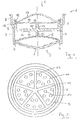
- a aerator 1 which has a cylindrical housing 2 with louvers 3.
- the air slots 3 are located in one plane of the housing 2, a plurality of air slots 3 are arranged distributed over the circumference of the housing 2.
- the water flows through the housing 2 in the illustration according to FIG. 1 from top to bottom.
- the housing has an inward circumferential projection 4.
- a sieve arrangement 5 is held by this attachment 4, which is inserted through the housing 2 from above during assembly.
- the sieve arrangement 5 consists of two sieves which are arranged in a lens-like manner, ie the upper sieve 6 has an upward curvature, the lower sieve 7 has a downward curvature.
- the circumferential edges of the screens 6 and 7 are supported on one another in the area of the housing 2.
- the upper sieve 6 has a fine mesh
- the lower sieve 7 has a large mesh.
- the sieves are made of a metal wire, the wire diameter of the coarse sieve should be about 0.5 mm with a clear mesh size of about 0.5 to 1.5 mm, but preferably 0.8 to 1.3 mm, the diameter of the wire of the fine Sieve about 0.15 to 0.20 mm with a mesh size of 0.1 to 0.2 mm.
- the housing 2 has a larger inner diameter in the area of an upper extension 8 than in the region of the lower extension 4.
- the housing 2 receives in the region of the extension 8 a circular, cap-shaped part 9 which has a plurality of holes 11 penetrating the bottom 10 .
- the part 9 On its side facing the sieve arrangement 5, the part 9 has a spacer 12, the free end of which comes into contact with the upper sieve 6 of the sieve arrangement 5. This ensures that when the part 9 is inserted, the sieve arrangement 5 is held in a defined manner in the aerator 1.
- the part 9 On its upper side, the part 9 has five ribs 13, which radiate from the center of the part 9 and on which a disc 14 with a central hole 15 is arranged.
- the disc 14 lies not only on the ribs 13, but also on a further circumferential projection 16 of the part 9. Above the disc 14 there is a fine sieve 17 which is curved outwards.
Landscapes
- Health & Medical Sciences (AREA)
- Life Sciences & Earth Sciences (AREA)
- Engineering & Computer Science (AREA)
- Hydrology & Water Resources (AREA)
- Public Health (AREA)
- Water Supply & Treatment (AREA)
- Domestic Plumbing Installations (AREA)
- Nozzles (AREA)
- Percussion Or Vibration Massage (AREA)
Priority Applications (1)
| Application Number | Priority Date | Filing Date | Title |
|---|---|---|---|
| AT86112917T ATE41687T1 (de) | 1985-09-25 | 1986-09-18 | Strahlregler fuer wasserhahnmundstuecke. |
Applications Claiming Priority (2)
| Application Number | Priority Date | Filing Date | Title |
|---|---|---|---|
| DE3534113 | 1985-09-25 | ||
| DE19853534113 DE3534113A1 (de) | 1985-09-25 | 1985-09-25 | Perlator fuer wasserhahnmundstuecke |
Publications (3)
| Publication Number | Publication Date |
|---|---|
| EP0216319A2 true EP0216319A2 (fr) | 1987-04-01 |
| EP0216319A3 EP0216319A3 (en) | 1987-05-27 |
| EP0216319B1 EP0216319B1 (fr) | 1989-03-22 |
Family
ID=6281858
Family Applications (1)
| Application Number | Title | Priority Date | Filing Date |
|---|---|---|---|
| EP86112917A Expired EP0216319B1 (fr) | 1985-09-25 | 1986-09-18 | Aérateur pour le bec d'un robinet d'eau |
Country Status (4)
| Country | Link |
|---|---|
| US (1) | US4789103A (fr) |
| EP (1) | EP0216319B1 (fr) |
| AT (1) | ATE41687T1 (fr) |
| DE (2) | DE3534113A1 (fr) |
Cited By (4)
| Publication number | Priority date | Publication date | Assignee | Title |
|---|---|---|---|---|
| EP0268844A1 (fr) * | 1986-11-04 | 1988-06-01 | Friedrich Grohe Aktiengesellschaft | Débouché d'écoulement d'eau |
| EP0284763A3 (en) * | 1987-04-02 | 1988-12-21 | Dieter Wildfang Kg | Jet regulator with a strainer attachment, and method for manufacturing such a jet regulator |
| EP2915927A3 (fr) * | 2011-11-25 | 2015-11-11 | Neoperl GmbH | Composant sanitaire |
| US9388557B2 (en) | 2011-11-28 | 2016-07-12 | Neoperl Gmbh | Sanitary installation part |
Families Citing this family (24)
| Publication number | Priority date | Publication date | Assignee | Title |
|---|---|---|---|---|
| US4902391A (en) * | 1986-05-06 | 1990-02-20 | Ibbott Jack Kenneth | Method and device for ionizing fluid |
| WO1998016693A1 (fr) * | 1996-10-11 | 1998-04-23 | Dieter Wildfang Gmbh | Ecoulement pour appareils sanitaires |
| GB2329134B (en) * | 1997-08-15 | 2001-02-14 | Reckitt & Colman Inc | Improvements to apparatus |
| DE19851360A1 (de) * | 1998-11-08 | 2000-05-25 | Spiegel Margret | Verfahren und Anordnung zum Einbringen von Gas in Flüssigkeiten über einen neuartigen Mischer |
| US6145756A (en) * | 1999-05-01 | 2000-11-14 | Kohls; Corwin | Gardening applicator for delivering liquid chemicals to selected vegetation |
| DE10027986B4 (de) * | 2000-06-06 | 2007-02-22 | Neoperl Gmbh | Sanitäres Einbauteil |
| ES2259390T3 (es) * | 2001-12-24 | 2006-10-01 | Koninklijke Philips Electronics N.V. | Dispositivo para bebidas para preparar una bebida con una capa de espuma en la superficie. |
| US6971591B2 (en) | 2002-10-16 | 2005-12-06 | Kohler Co. | Tamper-resistant flow modifier assembly |
| DE20307397U1 (de) * | 2003-05-13 | 2003-07-24 | Severin Elektrogeräte GmbH, 59846 Sundern | Halter für mit Kaffeemehl gefüllte kissenartige Pads |
| USD537916S1 (en) * | 2004-02-25 | 2007-03-06 | Neoperl Gmbh | Flow straightener for a discharge end of a sanitary fitting |
| USD536417S1 (en) * | 2005-02-23 | 2007-02-06 | Neoperl Gmbh | Flow straightener for a discharge end of a sanitary fitting |
| DE102004044158B3 (de) * | 2004-09-13 | 2006-01-12 | Hansa Metallwerke Ag | Wasserauslaufmundstück mit einem umschaltbaren Strahlreglereinsatz |
| US11267003B2 (en) | 2005-05-13 | 2022-03-08 | Delta Faucet Company | Power sprayer |
| CN101180132B (zh) | 2005-05-13 | 2010-11-24 | 印第安纳马斯科公司 | 动力喷水器 |
| US8424781B2 (en) * | 2006-02-06 | 2013-04-23 | Masco Corporation Of Indiana | Power sprayer |
| US7523614B2 (en) * | 2006-02-27 | 2009-04-28 | Mitsubishi Heavy Industries, Ltd. | Combustor |
| USD577416S1 (en) * | 2006-07-03 | 2008-09-23 | Neoperl Gmbh | Sanitary installation |
| WO2010070904A1 (fr) * | 2008-12-17 | 2010-06-24 | Toto株式会社 | Dispositif de douche |
| CN103290890A (zh) * | 2013-06-25 | 2013-09-11 | 邝朝威 | 一种出水嘴 |
| USD812722S1 (en) * | 2015-09-30 | 2018-03-13 | Neoperl Gmbh | Faucet stream straightener |
| USD844747S1 (en) * | 2015-09-30 | 2019-04-02 | Neoperl Gmbh | Faucet stream straightener |
| CN108905662A (zh) * | 2018-08-15 | 2018-11-30 | 乔登卫浴(江门)有限公司 | 一种递进射孔式粉碎细化结构 |
| DE102021120460A1 (de) | 2021-08-05 | 2023-02-09 | Neoperl Gmbh | Strahlregler |
| US12467244B2 (en) | 2022-07-29 | 2025-11-11 | Delta Faucet Company | Housing for a flow modifying device |
Family Cites Families (15)
| Publication number | Priority date | Publication date | Assignee | Title |
|---|---|---|---|---|
| US2541854A (en) * | 1948-09-22 | 1951-02-13 | Chicago Specialty Mfg Co Inc | Water aerating device |
| US2643104A (en) * | 1949-12-19 | 1953-06-23 | Orloff W Holden | Aerating device |
| FR1178993A (fr) * | 1957-07-17 | 1959-05-19 | Applic Des Gaz Soc D | Perfectionnements aux brûleurs à gaz pour réchauds et analogues |
| US2998933A (en) * | 1958-08-01 | 1961-09-05 | Elie P Aghnides | Water aerators |
| GB903139A (en) * | 1958-09-25 | 1962-08-09 | Elie Prodromos Aghnides | Improvements in water aerator diaphragms |
| US3067953A (en) * | 1960-11-14 | 1962-12-11 | Elie P Aghnides | Water aerator |
| US3138332A (en) * | 1962-05-14 | 1964-06-23 | Price Pfister Brass Mfg Compan | Aerator for faucets or the like |
| DE1904492U (de) * | 1964-08-17 | 1964-11-12 | Rokal G M B H | Vorrichtung zum belueften eines aus einem zapfhahn od. dgl. austretenden wasserstrahles. |
| US3334818A (en) * | 1965-09-22 | 1967-08-08 | Alfred M Moen | Swivel spray aerators |
| US3537651A (en) * | 1967-01-09 | 1970-11-03 | Rokal Gmbh Fa | Device for aerating water under pressure,particularly for household water supply |
| US3531051A (en) * | 1967-03-10 | 1970-09-29 | Rokal Gmbh Fa | Device for aerating the water jet emerging from a spigot or the like |
| US3684191A (en) * | 1970-11-05 | 1972-08-15 | Sidney J Shames | Aerator construction |
| US3851825A (en) * | 1973-02-15 | 1974-12-03 | American Standard Inc | Leak-proof laminar flow device |
| US4365755A (en) * | 1980-12-30 | 1982-12-28 | Aghnides Elie P | Aerator with reduced noise |
| DE8133875U1 (de) * | 1981-11-20 | 1983-05-05 | Dieter Wildfang KG, 7840 Müllheim | "strahlregler zum anschluss an sanitaer-armaturen o.dgl." |
-
1985
- 1985-09-25 DE DE19853534113 patent/DE3534113A1/de not_active Ceased
-
1986
- 1986-09-18 DE DE8686112917T patent/DE3662542D1/de not_active Expired
- 1986-09-18 AT AT86112917T patent/ATE41687T1/de not_active IP Right Cessation
- 1986-09-18 EP EP86112917A patent/EP0216319B1/fr not_active Expired
- 1986-09-24 US US06/910,976 patent/US4789103A/en not_active Expired - Lifetime
Cited By (9)
| Publication number | Priority date | Publication date | Assignee | Title |
|---|---|---|---|---|
| EP0268844A1 (fr) * | 1986-11-04 | 1988-06-01 | Friedrich Grohe Aktiengesellschaft | Débouché d'écoulement d'eau |
| EP0284763A3 (en) * | 1987-04-02 | 1988-12-21 | Dieter Wildfang Kg | Jet regulator with a strainer attachment, and method for manufacturing such a jet regulator |
| EP2915927A3 (fr) * | 2011-11-25 | 2015-11-11 | Neoperl GmbH | Composant sanitaire |
| EP3572593A3 (fr) * | 2011-11-25 | 2020-09-02 | Neoperl GmbH | Régulateur de jet |
| US9388557B2 (en) | 2011-11-28 | 2016-07-12 | Neoperl Gmbh | Sanitary installation part |
| US9580893B2 (en) | 2011-11-28 | 2017-02-28 | Neoperl Gmbh | Sanitary installation part |
| US9752305B2 (en) | 2011-11-28 | 2017-09-05 | Neoperl Gmbh | Sanitary installation part |
| US9909292B2 (en) | 2011-11-28 | 2018-03-06 | Neoperl Gmbh | Sanitary installation part |
| US10208466B2 (en) | 2011-11-28 | 2019-02-19 | Neoperl Gmbh | Sanitary installment part |
Also Published As
| Publication number | Publication date |
|---|---|
| EP0216319A3 (en) | 1987-05-27 |
| DE3662542D1 (en) | 1989-04-27 |
| US4789103A (en) | 1988-12-06 |
| EP0216319B1 (fr) | 1989-03-22 |
| ATE41687T1 (de) | 1989-04-15 |
| DE3534113A1 (de) | 1987-04-02 |
Similar Documents
| Publication | Publication Date | Title |
|---|---|---|
| EP0216319A2 (fr) | Aérateur pour le bec d'un robinet d'eau | |
| DE3207648C2 (de) | Unterwasser-Schlamm-(oder Sand-)Pumpe | |
| EP3350378B1 (fr) | Aérateur | |
| WO1998016695A1 (fr) | Regulateur de jet | |
| DE29704286U1 (de) | Sanitäre Auslaufvorrichtung | |
| DE8133875U1 (de) | "strahlregler zum anschluss an sanitaer-armaturen o.dgl." | |
| WO2004033807A1 (fr) | Regulateur de jet | |
| DE2554738A1 (de) | Halterung fuer einen diffusor fuer ein gas-speiserohr | |
| EP1606462A1 (fr) | Unite d'insertion sanitaire | |
| DE10312856A1 (de) | Sanitäre Einsetzeinheit | |
| DE102004008594B4 (de) | Sanitäre Auslaufvorrichtung | |
| DE4340024A1 (de) | Flüssigkeitsfilter für Kraftstoff | |
| DE8527320U1 (de) | Perlator für Wasserhahnmundstücke | |
| DE1619719C3 (fr) | ||
| DE20304659U1 (de) | Sanitäre Einsetzeinheit | |
| DE2852981A1 (de) | Wasserverteiler fuer ein zylindrisches filtersieb | |
| EP0744997A1 (fr) | Fond pour pomme de douche et pomme de douche | |
| DE29914781U1 (de) | Kleinkläranlage | |
| DE4102116C2 (de) | Strahlregler | |
| DE2154789C3 (de) | Auf einen Wasserauslauf aufschraubbares Mundstück | |
| EP0878237A2 (fr) | Fond pour pomme de douche et pomme de douche | |
| EP4696844A1 (fr) | Pièce d'insertion sanitaire, armature sanitaire et utilisation d'une pièce d'insertion sanitaire | |
| DE2220552C3 (de) | Strahlregler | |
| DE102024123195A1 (de) | Sanitäres Einsetzteil, Sanitärarmatur und Verwendung eines sanitären Einsetzteils | |
| DE9300755U1 (de) | Siebförmige Drainageelemente |
Legal Events
| Date | Code | Title | Description |
|---|---|---|---|
| PUAI | Public reference made under article 153(3) epc to a published international application that has entered the european phase |
Free format text: ORIGINAL CODE: 0009012 |
|
| AK | Designated contracting states |
Kind code of ref document: A2 Designated state(s): AT BE CH DE FR GB IT LI LU NL SE |
|
| PUAL | Search report despatched |
Free format text: ORIGINAL CODE: 0009013 |
|
| AK | Designated contracting states |
Kind code of ref document: A3 Designated state(s): AT BE CH DE FR GB IT LI LU NL SE |
|
| 17P | Request for examination filed |
Effective date: 19870827 |
|
| 17Q | First examination report despatched |
Effective date: 19880120 |
|
| GRAA | (expected) grant |
Free format text: ORIGINAL CODE: 0009210 |
|
| AK | Designated contracting states |
Kind code of ref document: B1 Designated state(s): AT BE CH DE FR GB IT LI LU NL SE |
|
| REF | Corresponds to: |
Ref document number: 41687 Country of ref document: AT Date of ref document: 19890415 Kind code of ref document: T |
|
| GBT | Gb: translation of ep patent filed (gb section 77(6)(a)/1977) | ||
| REF | Corresponds to: |
Ref document number: 3662542 Country of ref document: DE Date of ref document: 19890427 |
|
| ITF | It: translation for a ep patent filed | ||
| ET | Fr: translation filed | ||
| REG | Reference to a national code |
Ref country code: FR Ref legal event code: CA |
|
| PLBE | No opposition filed within time limit |
Free format text: ORIGINAL CODE: 0009261 |
|
| STAA | Information on the status of an ep patent application or granted ep patent |
Free format text: STATUS: NO OPPOSITION FILED WITHIN TIME LIMIT |
|
| 26N | No opposition filed | ||
| ITTA | It: last paid annual fee | ||
| EPTA | Lu: last paid annual fee | ||
| EAL | Se: european patent in force in sweden |
Ref document number: 86112917.9 |
|
| REG | Reference to a national code |
Ref country code: CH Ref legal event code: PUE Owner name: MATTHIAS RUHNKE |
|
| REG | Reference to a national code |
Ref country code: FR Ref legal event code: TP |
|
| BECA | Be: change of holder's address |
Free format text: 950531 *RUHNKE MATTHIAS;*RUHNKE CHRISTOF:ANDREAS-HOFER-STRASSE 1, 65189 WIESBADEN;CARL-SCHURICHT-STRASSE 2, 65187 WIESBADEN (DE) |
|
| NLS | Nl: assignments of ep-patents |
Owner name: MATTHIAS RUHNKE;CHRISTOF RUHNKE |
|
| REG | Reference to a national code |
Ref country code: GB Ref legal event code: 732E |
|
| REG | Reference to a national code |
Ref country code: GB Ref legal event code: IF02 |
|
| PGFP | Annual fee paid to national office [announced via postgrant information from national office to epo] |
Ref country code: GB Payment date: 20050913 Year of fee payment: 20 |
|
| PGFP | Annual fee paid to national office [announced via postgrant information from national office to epo] |
Ref country code: NL Payment date: 20050919 Year of fee payment: 20 |
|
| PGFP | Annual fee paid to national office [announced via postgrant information from national office to epo] |
Ref country code: FR Payment date: 20050920 Year of fee payment: 20 |
|
| PGFP | Annual fee paid to national office [announced via postgrant information from national office to epo] |
Ref country code: AT Payment date: 20050922 Year of fee payment: 20 Ref country code: BE Payment date: 20050922 Year of fee payment: 20 |
|
| PGFP | Annual fee paid to national office [announced via postgrant information from national office to epo] |
Ref country code: LU Payment date: 20050923 Year of fee payment: 20 Ref country code: SE Payment date: 20050923 Year of fee payment: 20 Ref country code: CH Payment date: 20050923 Year of fee payment: 20 |
|
| PGFP | Annual fee paid to national office [announced via postgrant information from national office to epo] |
Ref country code: IT Payment date: 20050926 Year of fee payment: 20 |
|
| PGFP | Annual fee paid to national office [announced via postgrant information from national office to epo] |
Ref country code: DE Payment date: 20050929 Year of fee payment: 20 |
|
| PG25 | Lapsed in a contracting state [announced via postgrant information from national office to epo] |
Ref country code: GB Free format text: LAPSE BECAUSE OF EXPIRATION OF PROTECTION Effective date: 20060917 |
|
| PG25 | Lapsed in a contracting state [announced via postgrant information from national office to epo] |
Ref country code: NL Free format text: LAPSE BECAUSE OF EXPIRATION OF PROTECTION Effective date: 20060918 |
|
| REG | Reference to a national code |
Ref country code: GB Ref legal event code: PE20 |
|
| REG | Reference to a national code |
Ref country code: CH Ref legal event code: PL |
|
| NLV7 | Nl: ceased due to reaching the maximum lifetime of a patent |
Effective date: 20060918 |
|
| EUG | Se: european patent has lapsed | ||
| BE20 | Be: patent expired |
Owner name: *RUHNKE MATTHIAS Effective date: 20060918 Owner name: *RUHNKE CHRISTOF Effective date: 20060918 |