EP0216256A1 - Niveleuse automotrice - Google Patents
Niveleuse automotrice Download PDFInfo
- Publication number
- EP0216256A1 EP0216256A1 EP86112541A EP86112541A EP0216256A1 EP 0216256 A1 EP0216256 A1 EP 0216256A1 EP 86112541 A EP86112541 A EP 86112541A EP 86112541 A EP86112541 A EP 86112541A EP 0216256 A1 EP0216256 A1 EP 0216256A1
- Authority
- EP
- European Patent Office
- Prior art keywords
- main frame
- motor grader
- frame
- grader according
- saddle
- Prior art date
- Legal status (The legal status is an assumption and is not a legal conclusion. Google has not performed a legal analysis and makes no representation as to the accuracy of the status listed.)
- Ceased
Links
Images

Classifications
-
- E—FIXED CONSTRUCTIONS
- E02—HYDRAULIC ENGINEERING; FOUNDATIONS; SOIL SHIFTING
- E02F—DREDGING; SOIL-SHIFTING
- E02F3/00—Dredgers; Soil-shifting machines
- E02F3/04—Dredgers; Soil-shifting machines mechanically-driven
- E02F3/76—Graders, bulldozers, or the like with scraper plates or ploughshare-like elements; Levelling scarifying devices
- E02F3/7636—Graders with the scraper blade mounted under the tractor chassis
- E02F3/765—Graders with the scraper blade mounted under the tractor chassis with the scraper blade being pivotable about a horizontal axis disposed perpendicular to the blade
-
- E—FIXED CONSTRUCTIONS
- E02—HYDRAULIC ENGINEERING; FOUNDATIONS; SOIL SHIFTING
- E02F—DREDGING; SOIL-SHIFTING
- E02F3/00—Dredgers; Soil-shifting machines
- E02F3/04—Dredgers; Soil-shifting machines mechanically-driven
- E02F3/76—Graders, bulldozers, or the like with scraper plates or ploughshare-like elements; Levelling scarifying devices
- E02F3/7636—Graders with the scraper blade mounted under the tractor chassis
- E02F3/764—Graders with the scraper blade mounted under the tractor chassis with the scraper blade being pivotable about a vertical axis
-
- Y—GENERAL TAGGING OF NEW TECHNOLOGICAL DEVELOPMENTS; GENERAL TAGGING OF CROSS-SECTIONAL TECHNOLOGIES SPANNING OVER SEVERAL SECTIONS OF THE IPC; TECHNICAL SUBJECTS COVERED BY FORMER USPC CROSS-REFERENCE ART COLLECTIONS [XRACs] AND DIGESTS
- Y10—TECHNICAL SUBJECTS COVERED BY FORMER USPC
- Y10T—TECHNICAL SUBJECTS COVERED BY FORMER US CLASSIFICATION
- Y10T403/00—Joints and connections
- Y10T403/71—Rod side to plate or side
- Y10T403/7117—Flanged or grooved rod
Definitions
- the invention relates to a motor grader with a forwardly extending main frame, on which a saddle is arranged for receiving hydraulic cylinders which are used to adjust a grader blade, the saddle being formed from at least one horizontally and at least two vertically running frame parts which partially surround the main frame.
- a motor grader of the type mentioned at the outset is already known (US Pat. No. 3,986,563), which has a main frame for receiving an adjustable grader blade, which for this purpose is pivotally connected to cantilever arms via hydraulic cylinders.
- the individual extension arms are connected to a bracket that completely surrounds the main frame and is then welded to it.
- very complex welding work is necessary, which must also withstand extreme loads, such as shear forces.
- the invention has for its object to provide the bracket or the individual fastening parts for receiving the hydraulic cylinder of the grader blade in such a way that they can be easily attached to the main frame and can also be exposed to extreme loads.
- This object is achieved by the features listed in the characterizing part of claim 1. Due to the advantageous design of the saddle, it can be easily placed on the main frame from above and connected to the main frame by means of transverse bolts, so that the saddle can also withstand extreme loads, since additional support for the saddle is easy the main frame by means of bolts.
- the saddle according to claim 2 from a front and a rear frame part is formed, which have a sufficiently large distance so that a better distribution of forces on the main frame takes place when the main frame is subjected to pressure or tensile stress.
- each frame part which is kept at a distance via the horizontally extending plate, is detachably connected to the main frame by means of a bolt, which is connected to the main frame by the corresponding legs and then by in the side walls provided holes are inserted in the main frame.
- the saddle can also be formed from an upper and a lower U-shaped frame part, which are brought up to the main frame from the top and the bottom, respectively, until the legs of the respective frame parts, which run parallel to one another, bear against one another. Then only the corresponding screw bolts need to be inserted or screwed into the legs in order to obtain a good connection between the upper and the lower frame part.
- a good fixation of the individual frame parts or fastening parts of the saddle can be achieved by providing recesses in the area of the upper and lower corners of the side parts of the main frame, which are used to accommodate counterparts provided on the frame parts. This creates a perfect fit for the frame parts or fastening parts of the saddle on the main frame.
- screw bolts can be inserted into the outer ends of the bolts for this purpose, said bolts releasably connecting the bolts to the main frame.
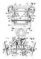
- a motor grader is designated by 11 in FIGS. 1 and 2, which consists of a tractor part 13 and a main frame 17 that can be supported on wheels 15 and 21.
- the main frame 17 is connected to the tractor part 13 in a horizontally pivotable manner by means of a joint device 19.
- a driver's cab 23 provided on the tractor part 13 there are the operating devices by means of which the various hydraulic devices are installed the motor grader and the control devices can be operated.
- a grader blade 24 is arranged on a rotating ring 25 below the main frame 17.
- the turntable 25 has an inner ring gear which can be rotated by means of a hydraulic motor 29 arranged on a pull frame 27.
- the front end of the pull frame 27 is pivotally connected to the main frame 17 by means of a universal joint device 28, while the rear end of the pull frame 27 is connected to the slewing ring 25.
- a saddle 31 is arranged on the main frame 17 (see FIGS. 2 to 5).
- a first Y-shaped support device 33 has an articulated arm 35 which is connected in an articulated manner to the saddle 31 and for this purpose is received between a front and rear frame part 37 and 39.
- the other articulated arm 41 of the carrying device 33 is articulated at one end to a cross member 43.
- a second carrying device 45 like the carrying device 33, is equipped with an articulated arm 47, which is also articulated between the frame parts 37 and 39 of the saddle 31.
- the carrying device 45 also has a second articulated arm 49, which is also articulated to the cross member 43.
- the carrying devices 33 and 45 are provided on both sides of the main frame 17.
- the grader blade carrying device with its joint devices is designated 51 overall and consists of the joint devices 33 and 45, the cross member 43 and retractable and extendable hydraulic cylinders 53 and 55, the piston rods of which are connected to the carrying devices 33 and 45 via joints 57 and 59.
- the piston rods of the hydraulic cylinders 53 and 55 are connected at the ends to the pull frame 27 by means of joints 61 and 63, respectively.
- a retractable and extendable hydraulic cylinder 77 is also included means of a universal joint 79 connected to the pull frame 27 at one end.
- the hydraulic cylinder 77 runs diagonally and transversely to the main frame 17, so that the piston rod 81 can be connected in an articulated manner to the arm 49 of the carrying device 45 by means of a universal joint 83.
- the carrying device 45 has numerous openings or bores 85 directed towards the front, which are arranged at a distance from one another and serve to connect a locking bolt 87.
- the connecting device or the locking bolt 87 is described in detail in US Pat. No. 3,986,563.
- the locking bolt 87 can be inserted into the corresponding bores 85 of the cross member 43.
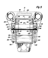
- the main frame 17 is provided with a first pair of vertically extending, upwardly open recesses 100 for receiving and fixing the saddle 31, which are in the area of the upper edges of the left and right side walls 102 and 104 of the main frame 17 are provided and which lie on the same transverse plane.
- a second pair of upwardly facing recesses 106 are provided in the area of the upper edge of the left and right side walls 102 and 104.
- the recesses 106 lie behind the recesses 100.
- a third pair of vertically aligned recesses 108 is provided in the region of the lower edges of the left and right side walls 102 and 104 of the main frame 17 and is also on the same transverse plane.
- the cutouts 108 are located below the cutouts 106.
- the cutouts 100, 106 and 108 are formed, for example, by milling out of the main frame 17 and serve as a seat for the frame parts 37, 39.
- the side walls 102 and 104 of the main frame 17 have a rear bore 110 and a front bore 112.
- the bores 110 are arranged in the side walls 102 and 104 on a same transverse plane, similar to the Boh stanchions 112.
- the bores 110 and 112 lie close to the longitudinal central axis of the main frame 17.
- Cylindrical inserts 114 and 116 are received in the bores 110 and 112 and welded to the main frame 17, for example.
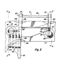
- the saddle 31 has an upper fastening part 120 and a lower fastening part 122.
- the upper fastening part 120 of the saddle 31 consists of an elongated plate 124 which is provided between the frame parts 37 and 39 and firmly connects them to one another.
- Side bars 130 and 132 extend between the front frame part 37 and the rear frame part 39 of the upper fastening part 120.
- First and second struts 133 and 135, which are arranged at a distance from one another and on the same, are provided on the rear frame part 39 Transverse plane.
- a first bolt 134 is received at the end in the sockets 114 and extends beyond the sockets 114 and the side walls 102 and 104.
- a second bolt 136 is received in the bushings 116 in a manner similar to the bolt 134 and extends beyond these and beyond the side walls 102 and 104.
- the upper fastening part 120 of the saddle 31 extends in the longitudinal direction on the main frame 17, the front and rear frame parts 37 and 39 spanning or overlapping the main frame 17.
- the rear frame part 39 has system parts 138 which connect to the cutouts 106 as press fits.
- the struts 133 and 135 of the frame part 39 have horizontally extending, fork-shaped recesses directed towards the rear, which serve to receive the bolts 134.
- Bolts 142 extend through horizontally extending openings provided at the ends of bolts 134. The bolts are also screwed into the struts 133 and 135 (see Fig. 3).
- the front frame part 37 has inner contact parts 146 which act as press fits in the Recesses 100 are added. In addition, the front frame part 37 sits with its legs on contact parts 150 which are provided at the end of the bolt 136 (see FIG. 3).
- Bolts 152 extend through vertically running openings which are provided at the end in the bolts 136 and which are screwed into the frame part 37.
- the lower fastening part 122 of the saddle 31 spans the underside of the main frame 17.
- the lower fastening part 122 has inner contact parts 154 and 156 which are received as press fits in the cutouts 108.
- the lower fastening part 122 is also connected to the struts 133 and 135 via numerous bolts 158, which extend through the lower fastening part 122 and are received in the contact parts.
- the advantageous design and arrangement of the main frame 17 Due to the advantageous design and arrangement of the main frame 17, high local tensile or compressive stresses are avoided, thereby making a special reinforcement of the main frame 17 in the saddle area unnecessary. Furthermore, the advantageous design of the saddle 31 and the individual components in the area of the saddle allow simple assembly and easy access to the fastening parts and hydraulic cylinders during maintenance work.
Landscapes
- Engineering & Computer Science (AREA)
- Mechanical Engineering (AREA)
- Mining & Mineral Resources (AREA)
- Civil Engineering (AREA)
- General Engineering & Computer Science (AREA)
- Structural Engineering (AREA)
- Operation Control Of Excavators (AREA)
- Control Of Electric Motors In General (AREA)
- Crushing And Pulverization Processes (AREA)
- Structure Of Transmissions (AREA)
Applications Claiming Priority (2)
| Application Number | Priority Date | Filing Date | Title |
|---|---|---|---|
| US06/780,048 US4696350A (en) | 1985-09-25 | 1985-09-25 | Motor grader with saddle mounted to transverse pin on main frame |
| US780048 | 1985-09-25 |
Publications (1)
| Publication Number | Publication Date |
|---|---|
| EP0216256A1 true EP0216256A1 (fr) | 1987-04-01 |
Family
ID=25118403
Family Applications (1)
| Application Number | Title | Priority Date | Filing Date |
|---|---|---|---|
| EP86112541A Ceased EP0216256A1 (fr) | 1985-09-25 | 1986-09-10 | Niveleuse automotrice |
Country Status (6)
| Country | Link |
|---|---|
| US (1) | US4696350A (fr) |
| EP (1) | EP0216256A1 (fr) |
| JP (1) | JPS6299525A (fr) |
| AU (1) | AU6295786A (fr) |
| BR (1) | BR8604607A (fr) |
| CA (1) | CA1251039A (fr) |
Families Citing this family (12)
| Publication number | Priority date | Publication date | Assignee | Title |
|---|---|---|---|---|
| US4807461A (en) * | 1986-01-21 | 1989-02-28 | Deere & Company | Motor grader main frame |
| US20050252669A1 (en) * | 2004-05-14 | 2005-11-17 | Caterpillar, Inc. | Work machine with a formed beam frame |
| US7451840B2 (en) * | 2004-11-29 | 2008-11-18 | Deere & Company | Articulated crawler dozer with direct load path structure |
| US7584812B2 (en) | 2004-11-29 | 2009-09-08 | Deere & Company | Articulated dozer with suspension and suspension lockout |
| US7192034B2 (en) * | 2004-11-29 | 2007-03-20 | Deere & Company | Load based suspension motion limiting |
| US7641007B2 (en) * | 2004-11-29 | 2010-01-05 | Deere & Company | Dynamic blade distance ratio system and method |
| US7581598B2 (en) * | 2004-11-29 | 2009-09-01 | Deere & Company | Blade motion reduction |
| US7503411B2 (en) * | 2004-11-29 | 2009-03-17 | Deere & Company | Articulated dozer with frame structure for decreased height variation in the vehicle chassis |
| US9096994B2 (en) | 2012-02-15 | 2015-08-04 | Deere & Company | Bottom mount blade positioning assembly for a motor grader |
| WO2014203323A1 (fr) * | 2013-06-18 | 2014-12-24 | 株式会社小松製作所 | Niveleuse |
| US11066809B2 (en) * | 2018-10-26 | 2021-07-20 | Deere & Company | Motor grader saddle positioning system and method thereof |
| CN112359894B (zh) * | 2020-10-30 | 2022-04-05 | 江苏徐工工程机械研究院有限公司 | 平地机鞍架以及平地机 |
Citations (5)
| Publication number | Priority date | Publication date | Assignee | Title |
|---|---|---|---|---|
| US2655743A (en) * | 1950-11-16 | 1953-10-20 | W A Riddell Corp | Road working apparatus |
| FR1448903A (fr) * | 1965-06-21 | 1966-08-12 | Deere & Co | Machine de travaux publics pour la construction des routes, notamment niveleuse |
| FR1528261A (fr) * | 1967-06-20 | 1968-06-07 | Deere & Co | Machine de travaux publics, notamment niveleuse |
| US3739861A (en) * | 1971-02-02 | 1973-06-19 | Caterpillar Tractor Co | Blade lift/centershift controls for motor graders |
| US4340119A (en) * | 1978-05-06 | 1982-07-20 | Champion Road Machinery Limited | Motor grader with bar linkage blade positioning apparatus |
Family Cites Families (7)
| Publication number | Priority date | Publication date | Assignee | Title |
|---|---|---|---|---|
| US2237586A (en) * | 1940-05-24 | 1941-04-08 | Allis Chalmers Mfg Co | Road machine |
| US2858153A (en) * | 1957-02-21 | 1958-10-28 | Mc Graw Edison Co | Supporting attachment |
| US3327413A (en) * | 1964-06-22 | 1967-06-27 | Deere & Co | Material grading implement |
| US3454110A (en) * | 1966-06-21 | 1969-07-08 | Deere & Co | Saddle structure for earth grader |
| US3415554A (en) * | 1966-10-17 | 1968-12-10 | Unistrut Corp | Structural joint assembly and connectors therefor |
| US3986563A (en) * | 1975-05-01 | 1976-10-19 | Deere & Company | Suspension and control linkage for a grade blade support frame |
| US4496261A (en) * | 1981-06-12 | 1985-01-29 | Hazeltine Corporation | Column/sheet metal interface |
-
1985
- 1985-09-25 US US06/780,048 patent/US4696350A/en not_active Expired - Fee Related
-
1986
- 1986-08-27 CA CA000516901A patent/CA1251039A/fr not_active Expired
- 1986-09-10 EP EP86112541A patent/EP0216256A1/fr not_active Ceased
- 1986-09-19 AU AU62957/86A patent/AU6295786A/en not_active Abandoned
- 1986-09-22 JP JP61224072A patent/JPS6299525A/ja active Pending
- 1986-09-24 BR BR8604607A patent/BR8604607A/pt unknown
Patent Citations (5)
| Publication number | Priority date | Publication date | Assignee | Title |
|---|---|---|---|---|
| US2655743A (en) * | 1950-11-16 | 1953-10-20 | W A Riddell Corp | Road working apparatus |
| FR1448903A (fr) * | 1965-06-21 | 1966-08-12 | Deere & Co | Machine de travaux publics pour la construction des routes, notamment niveleuse |
| FR1528261A (fr) * | 1967-06-20 | 1968-06-07 | Deere & Co | Machine de travaux publics, notamment niveleuse |
| US3739861A (en) * | 1971-02-02 | 1973-06-19 | Caterpillar Tractor Co | Blade lift/centershift controls for motor graders |
| US4340119A (en) * | 1978-05-06 | 1982-07-20 | Champion Road Machinery Limited | Motor grader with bar linkage blade positioning apparatus |
Also Published As
| Publication number | Publication date |
|---|---|
| US4696350A (en) | 1987-09-29 |
| BR8604607A (pt) | 1987-05-26 |
| AU6295786A (en) | 1987-03-26 |
| CA1251039A (fr) | 1989-03-14 |
| JPS6299525A (ja) | 1987-05-09 |
Similar Documents
| Publication | Publication Date | Title |
|---|---|---|
| AT396097B (de) | Chassis fuer raupenfahrwerke | |
| DE69423972T2 (de) | Endabschnitt eines rahmenteils für ein fahrzeug | |
| DE602004000685T2 (de) | Aufhängung eines Triebwerks unter einer Flugzeugtragfläche | |
| EP0530594A1 (fr) | Cadre auxiliaire pour un véhicule automobile | |
| DE3018831A1 (de) | Befestigungsvorrichtung | |
| DE2559040C3 (de) | Planierfahrzeug mit einem Planierschild | |
| EP0216256A1 (fr) | Niveleuse automotrice | |
| DE2415363B2 (de) | Vorrichtung zur Befestigung eines Arbeitsgerätes an einem Fahrzeug | |
| EP0233367A1 (fr) | Niveleuse | |
| DE1801660A1 (de) | Schlepper-Geraetekupplung | |
| DE602004001565T2 (de) | Aufhängevorrichtung eines Triebwerks unter einem Flugzeugflügel | |
| DE2406342C3 (de) | Scherenhebevorrichtung, insbesondere für Kippfahrzeuge | |
| DE60012362T3 (de) | Befestigungsvorrichtung einer sattelkupplung | |
| DE2953352A1 (de) | Vorrichtung zur schnellbefestigung einer vorzugsweise elektrischen sitzverstelleinrichtung am fahrzeugboden eines kraftfahrzeugs und/oder eines sitzes an der sitzverstelleinrichtung | |
| EP3696054B1 (fr) | Châssis véhicule modulaire pourvu de porte à faux arrière | |
| DE69222917T2 (de) | Verbindung des Untergestells eines Krans an die Raupenkette(n) | |
| EP3456888B1 (fr) | Flèche de pelle et pelle excavatrice | |
| DE2647778C3 (de) | Tieflöffelbagger | |
| DE2952450A1 (de) | Tragarm, insbesondere ausleger fuer bagger o.dgl. | |
| DE2528177C2 (de) | Aufreißer an einem Erdbaufahrzeug | |
| DE2648324A1 (de) | Fahrgestell fuer ein fahrzeug | |
| DE69713050T2 (de) | Kupplungsvorrichtung für den vorderrahmen einer gelenkigen arbeitsmaschine | |
| DE3874084T2 (de) | Verbinder fuer den aufbau und das chassis eines fahrzeuges. | |
| DE2658214A1 (de) | Stabilisierungsbaugruppe fuer die geraetetragkonstruktion von zugmaschinen o.dgl. | |
| DE2415107B2 (de) | Lenkbares Selbstfahr-Ladegerät |
Legal Events
| Date | Code | Title | Description |
|---|---|---|---|
| PUAI | Public reference made under article 153(3) epc to a published international application that has entered the european phase |
Free format text: ORIGINAL CODE: 0009012 |
|
| AK | Designated contracting states |
Kind code of ref document: A1 Designated state(s): DE FR GB |
|
| 17P | Request for examination filed |
Effective date: 19870926 |
|
| 17Q | First examination report despatched |
Effective date: 19880610 |
|
| STAA | Information on the status of an ep patent application or granted ep patent |
Free format text: STATUS: THE APPLICATION HAS BEEN REFUSED |
|
| 18R | Application refused |
Effective date: 19881210 |
|
| RIN1 | Information on inventor provided before grant (corrected) |
Inventor name: STUBBEN, DAVID WILLIAM Inventor name: RUHTER, MARTIN LAVERN Inventor name: BRIMEYER, DENNIS ARTHUR |