EP0216051B1 - Porte-outil - Google Patents
Porte-outil Download PDFInfo
- Publication number
- EP0216051B1 EP0216051B1 EP86109803A EP86109803A EP0216051B1 EP 0216051 B1 EP0216051 B1 EP 0216051B1 EP 86109803 A EP86109803 A EP 86109803A EP 86109803 A EP86109803 A EP 86109803A EP 0216051 B1 EP0216051 B1 EP 0216051B1
- Authority
- EP
- European Patent Office
- Prior art keywords
- base plate
- cutting edge
- intermediate member
- serration
- tool holder
- Prior art date
- Legal status (The legal status is an assumption and is not a legal conclusion. Google has not performed a legal analysis and makes no representation as to the accuracy of the status listed.)
- Expired
Links
Images

Classifications
-
- B—PERFORMING OPERATIONS; TRANSPORTING
- B23—MACHINE TOOLS; METAL-WORKING NOT OTHERWISE PROVIDED FOR
- B23B—TURNING; BORING
- B23B29/00—Holders for non-rotary cutting tools; Boring bars or boring heads; Accessories for tool holders
- B23B29/03—Boring heads
Definitions
- the invention relates to a tool carrier, in particular for a multi-cutting tool, with a base plate which can be driven to rotate in use and has a central fastening opening, in particular a threaded bore, with serration on a base plate surface, with a serrated cutting edge carrier and with connecting screws for producing a rigid , Detachable connection between the base plate and the cutter holder using the positioning effect of intermeshing serration areas, wherein for the purpose of radial adjustment of the cutter holder relative to the base plate, at least one elongated hole in the adjustment direction, which is penetrated by a connecting screw, is provided in one of the elements to be connected is.
- Such a tool holder is known from DE-A 3 130 229.
- the serrations on the base body, on the one hand, and on the cutter carrier, on the other hand engage directly with one another, and these elements are also screwed directly to one another with the aid of the connecting screws, with at least one elongated hole being provided in one of the elements to be connected, which opposes a radial adjustment of the cutter carrier of the base plate.
- the cutter holder is also connected to the base plate by means of two connecting screws to achieve sufficient stability, so that two parallel elongated holes are accordingly provided.
- a large boring tool which comprises a bridge receptacle to which a bridge serving as a tool carrier can be attached, which in turn serves to hold slides serving as cutter carriers.
- the known tool can be adapted to bores of different diameters by using bridges of different lengths, the carriages making it possible to position the cutting tools at the desired radius.
- the radial adjustment path for the carriages is also limited in these known tools or tool carriers, since a sufficient stability of the holder of the carriage can only be achieved if the carriage and the adjacent bridge end overlap to an appropriate length.
- the object of the invention is to increase the radial adjustment path for the cutter holder relative to the base plate without a loss of stability in the case of a tool holder of the type specified at the beginning.
- a plate-shaped intermediate piece having two main surfaces is provided, the serration provided on one main surface of which engages with the serration of the base body and the serration provided on its other main surface engages with the serration of the cutter carrier, wherein the intermediate piece is detachably connected on the one hand to the base plate and on the other hand to the cutter holder independently of one another.
- the tool carrier according to the invention that, through the use of the intermediate piece, there are two areas in which a radial adjustment can be made separately from one another, so that the radial adjustment path can be increased considerably while the overlap length of the respective serrations interacting in each case can be increased considerably .
- the axial distance of the cutting edge of the cutter carrier from the main surface of the base plate serving to fasten the same can be varied by the choice of the thickness of the intermediate piece, without the cutter carrier itself having to be adjustable in the axial direction relative to the base plate.
- an elongated hole connection is provided between two of the three elements to be connected to one another - base plate, intermediate piece, cutter support - which enables radial adjustment if a corresponding number of intermediate pieces is available which, after being fastened to the adjacent one Project component in the radial direction at different distances above it.
- elongated hole connections will be provided both between the cutter carrier and the intermediate piece and between the base plate and the intermediate piece in order to achieve greater flexibility with regard to the radial adjustment options, in particular with regard to the fact that for the axial positioning preferably intermediate pieces with different Thickness must be kept ready.
- each intermediate piece has two serrations on both sides has provided parts which are connected to one another via an angled connecting web in which a thread is provided, into which a set screw is screwed, the axis of which extends in the radial direction and the inner end of which with an axially extending supporting surface of the base plate cooperates so that the adjusting screw can be used to fine-tune the radial position of the intermediate piece with respect to the base plate before the connecting screws in question are firmly tightened.
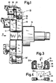
- FIG. 1 shows a tool arrangement with two tool carriers 10, 12, of which the tool carrier 10 is designed according to a preferred embodiment of the invention, while the tool carrier 12 is designed in a conventional manner, the two tool carriers 10, 12 one behind the other in the axial direction are attached to a tool shaft 14 in the usual manner, as is described in detail, for example, in DE-PS 31 30 229, the disclosure of which is hereby expressly incorporated by reference to the attachment of the tool carriers 10, 12 to the tool spindle 14.
- the tool carrier 10 comprises a base plate 16, the front side pointing to the left in FIG. 1 is shown in detail in FIG. 2.
- the base plate surface forming the front side of the base plate 16 - one of the main surfaces of the base plate - is provided with a total of four serrations 18, each of the serrations 18 comprising two fields, one on each side of one of the relevant serrations 18 associated recess 20 of the base plate 16.
- the teeth of each of the serrations 18 run parallel to one another in a plane perpendicular to the axis of rotation A of the base plate 16, the teeth of adjacent serration areas overlapping in their radially inner part in a known manner, as is shown in FIG. 2.
- a threaded bore 22 is also provided in each of the partial areas of each of the serrations 18.
- a plate-shaped intermediate piece 24 is shown, the front side of which is pointing to the left in FIG. 1 and is visible in FIG. 3 1 of the base plate 16 facing rear side each with a serration 26 and 28 respectively.
- the intermediate piece 24, as is clear from FIGS. 1, 3 and 4, consists of two plate-shaped parts 24a, 24b, which are connected to one another via a likewise plate-shaped connecting web 24c, which is angled relative to the parts 24a, 24b, and in which Position of use of the intermediate piece 24 forms an arm extending in the axial direction (cf. Rg. 1), which engages in the associated recess 20 of the base plate 16.
- Each of the parts 24a, 24b of the intermediate piece 24 is provided with an elongated hole 30 and with a threaded bore 32. Furthermore, the connecting web 24c is likewise provided with a threaded bore 34, the axis of which runs perpendicular to the axes of the threaded bore 32 and parallel to the teeth of the serrations 26, 28 of the intermediate piece 24.
- the intermediate piece 24 in the radial direction relative to the base plate 16 and, on the other hand, of adjusting the cutter holder 38 in the radial direction relative to the intermediate piece 24, so that the position of the cutter holder 38 or the one attached to it Cutting edge 42 a considerable radial adjustment path is available, the various serrations 18, 26, 28, 40 overlapping one another even in the outermost radial position of the cutting edge carrier 38 so that a stable mounting of the cutting edge carrier or an exact positioning of those provided thereon Cutting edge 42 is guaranteed.
- the thickness of the intermediate piece 24 can be varied according to the requirements so that the cutting edge provided on the cutting edge carrier 38 can be brought into the desired axial position.
- the intermediate piece 24 can be omitted in one of the cutter carriers, as is shown in FIG. 1 for a cutter carrier 38 '.
- the radial position required for the relevant blade holder with the required stability can be achieved by the cooperation of the serrations 18 and 40.
Landscapes
- Engineering & Computer Science (AREA)
- Mechanical Engineering (AREA)
- Drilling Tools (AREA)
Claims (6)
Applications Claiming Priority (2)
| Application Number | Priority Date | Filing Date | Title |
|---|---|---|---|
| DE19853525853 DE3525853A1 (de) | 1985-07-19 | 1985-07-19 | Werkzeugtraeger |
| DE3525853 | 1985-07-19 |
Publications (2)
| Publication Number | Publication Date |
|---|---|
| EP0216051A1 EP0216051A1 (fr) | 1987-04-01 |
| EP0216051B1 true EP0216051B1 (fr) | 1989-07-12 |
Family
ID=6276223
Family Applications (1)
| Application Number | Title | Priority Date | Filing Date |
|---|---|---|---|
| EP86109803A Expired EP0216051B1 (fr) | 1985-07-19 | 1986-07-17 | Porte-outil |
Country Status (2)
| Country | Link |
|---|---|
| EP (1) | EP0216051B1 (fr) |
| DE (2) | DE3525853A1 (fr) |
Cited By (1)
| Publication number | Priority date | Publication date | Assignee | Title |
|---|---|---|---|---|
| CN111546129A (zh) * | 2020-04-27 | 2020-08-18 | 南京信息职业技术学院 | 一种可以精确调定的浮动镗刀块 |
Families Citing this family (1)
| Publication number | Priority date | Publication date | Assignee | Title |
|---|---|---|---|---|
| DE10011113A1 (de) * | 2000-03-09 | 2001-09-13 | Komet Stahlhalter Werkzeuge | Maschinenwerkzeug mit verstellbarer Schneide |
Family Cites Families (2)
| Publication number | Priority date | Publication date | Assignee | Title |
|---|---|---|---|---|
| US2900704A (en) * | 1957-04-22 | 1959-08-25 | Corlise M Sweet | Adjustable tool mounting for lathes |
| DE3130229C2 (de) * | 1981-07-31 | 1983-12-29 | Hahn & Kolb, 7000 Stuttgart | Mehrschneidenwerkzeug |
-
1985
- 1985-07-19 DE DE19853525853 patent/DE3525853A1/de not_active Withdrawn
-
1986
- 1986-07-17 DE DE8686109803T patent/DE3664271D1/de not_active Expired
- 1986-07-17 EP EP86109803A patent/EP0216051B1/fr not_active Expired
Cited By (1)
| Publication number | Priority date | Publication date | Assignee | Title |
|---|---|---|---|---|
| CN111546129A (zh) * | 2020-04-27 | 2020-08-18 | 南京信息职业技术学院 | 一种可以精确调定的浮动镗刀块 |
Also Published As
| Publication number | Publication date |
|---|---|
| DE3664271D1 (en) | 1989-08-17 |
| EP0216051A1 (fr) | 1987-04-01 |
| DE3525853A1 (de) | 1987-01-29 |
Similar Documents
| Publication | Publication Date | Title |
|---|---|---|
| DE2339873C2 (de) | Anordnung zum Einstellen und Befestigen eines ein Schneidplättchen tragenden Blocks in einer nutförmigen Aufnahme im Werkzeugkörper eines spanabhebenden Werkzeugs | |
| DE3211766A1 (de) | Schlitzschneider | |
| DE7523920U (de) | Bohrstange o.dgl. | |
| DE3432050C2 (fr) | ||
| EP0182290A2 (fr) | Tête de fraisage | |
| DE2614599B2 (de) | Reibahle für die Bearbeitung eng tolerierter Bohrungen | |
| DE3240165A1 (de) | Werkzeugmaschine zum gleichzeitigen fraesen mehrerer flaechen vom freien ende eines werkstuecks her | |
| DE3916564A1 (de) | Werkzeug mit verstellbarer wechselkassette | |
| DE1577451A1 (de) | Verfahren zum Nachschleifen eines Werkzeugstahles | |
| EP1401601B2 (fr) | Dispositif de coupe | |
| DE102011012663B4 (de) | Messerhalterung zur Befestigung eines Hackmessers | |
| DE2941179B1 (de) | Zer?kzeug | |
| DE3530745A1 (de) | Messerkopf | |
| DE2533495C3 (de) | Bohrstange | |
| EP0131136B1 (fr) | Aléseur à tête conique | |
| DE2140004A1 (de) | Senk- und fraeswerkzeug | |
| EP0216051B1 (fr) | Porte-outil | |
| DE2542346C3 (de) | Innenräumwerkzeug, insbesondere zur Herstellung von Profilnuten | |
| DE3008008C2 (de) | Spanabhebendes Werkzeug | |
| CH652951A5 (de) | Werkzeug zum aufbohren und plansenken. | |
| EP0133197A1 (fr) | Outillage à raboter et profilmètre s'y adaptant | |
| EP0355305A2 (fr) | Fraise disque | |
| DE2625983A1 (de) | Bohrwerkzeug mit zwei einzeln verstellbaren schneiden | |
| DE3026513C2 (de) | Werkzeug zum Aufbohren und Plansenken | |
| EP1123786A2 (fr) | Tête de fraisage |
Legal Events
| Date | Code | Title | Description |
|---|---|---|---|
| PUAI | Public reference made under article 153(3) epc to a published international application that has entered the european phase |
Free format text: ORIGINAL CODE: 0009012 |
|
| AK | Designated contracting states |
Kind code of ref document: A1 Designated state(s): AT BE CH DE FR GB IT LI NL SE |
|
| 17P | Request for examination filed |
Effective date: 19870527 |
|
| RAP1 | Party data changed (applicant data changed or rights of an application transferred) |
Owner name: HAHN & KOLB GMBH & CO. |
|
| 17Q | First examination report despatched |
Effective date: 19880426 |
|
| GRAA | (expected) grant |
Free format text: ORIGINAL CODE: 0009210 |
|
| AK | Designated contracting states |
Kind code of ref document: B1 Designated state(s): CH DE LI |
|
| REF | Corresponds to: |
Ref document number: 3664271 Country of ref document: DE Date of ref document: 19890817 |
|
| PLBE | No opposition filed within time limit |
Free format text: ORIGINAL CODE: 0009261 |
|
| STAA | Information on the status of an ep patent application or granted ep patent |
Free format text: STATUS: NO OPPOSITION FILED WITHIN TIME LIMIT |
|
| 26N | No opposition filed | ||
| REG | Reference to a national code |
Ref country code: CH Ref legal event code: PUE Owner name: HAHN & KOLB WERKZEUGE GMBH |
|
| REG | Reference to a national code |
Ref country code: CH Ref legal event code: PUE Owner name: HK PRAEZISIONSTECHNIK GMBH |
|
| PGFP | Annual fee paid to national office [announced via postgrant information from national office to epo] |
Ref country code: CH Payment date: 19960611 Year of fee payment: 11 |
|
| PG25 | Lapsed in a contracting state [announced via postgrant information from national office to epo] |
Ref country code: LI Free format text: LAPSE BECAUSE OF NON-PAYMENT OF DUE FEES Effective date: 19970731 Ref country code: CH Free format text: LAPSE BECAUSE OF NON-PAYMENT OF DUE FEES Effective date: 19970731 |
|
| REG | Reference to a national code |
Ref country code: CH Ref legal event code: PL |
|
| PGFP | Annual fee paid to national office [announced via postgrant information from national office to epo] |
Ref country code: DE Payment date: 19990429 Year of fee payment: 13 |
|
| PG25 | Lapsed in a contracting state [announced via postgrant information from national office to epo] |
Ref country code: DE Free format text: LAPSE BECAUSE OF NON-PAYMENT OF DUE FEES Effective date: 20000503 |