EP0215547B1 - Verfahren und Vorrichtung zur Kompensierung von Wirbelströmen in magnetischer Resonanzabbildung - Google Patents
Verfahren und Vorrichtung zur Kompensierung von Wirbelströmen in magnetischer Resonanzabbildung Download PDFInfo
- Publication number
- EP0215547B1 EP0215547B1 EP86304903A EP86304903A EP0215547B1 EP 0215547 B1 EP0215547 B1 EP 0215547B1 EP 86304903 A EP86304903 A EP 86304903A EP 86304903 A EP86304903 A EP 86304903A EP 0215547 B1 EP0215547 B1 EP 0215547B1
- Authority
- EP
- European Patent Office
- Prior art keywords
- gradient
- signal
- field
- magnetic field
- energization
- Prior art date
- Legal status (The legal status is an assumption and is not a legal conclusion. Google has not performed a legal analysis and makes no representation as to the accuracy of the status listed.)
- Expired
Links
Images

Classifications
-
- G—PHYSICS
- G01—MEASURING; TESTING
- G01R—MEASURING ELECTRIC VARIABLES; MEASURING MAGNETIC VARIABLES
- G01R33/00—Arrangements or instruments for measuring magnetic variables
- G01R33/02—Measuring direction or magnitude of magnetic fields or magnetic flux
- G01R33/028—Electrodynamic magnetometers
-
- G—PHYSICS
- G01—MEASURING; TESTING
- G01R—MEASURING ELECTRIC VARIABLES; MEASURING MAGNETIC VARIABLES
- G01R33/00—Arrangements or instruments for measuring magnetic variables
- G01R33/20—Arrangements or instruments for measuring magnetic variables involving magnetic resonance
- G01R33/28—Details of apparatus provided for in groups G01R33/44 - G01R33/64
- G01R33/38—Systems for generation, homogenisation or stabilisation of the main or gradient magnetic field
- G01R33/385—Systems for generation, homogenisation or stabilisation of the main or gradient magnetic field using gradient magnetic field coils
-
- G—PHYSICS
- G01—MEASURING; TESTING
- G01R—MEASURING ELECTRIC VARIABLES; MEASURING MAGNETIC VARIABLES
- G01R33/00—Arrangements or instruments for measuring magnetic variables
- G01R33/20—Arrangements or instruments for measuring magnetic variables involving magnetic resonance
- G01R33/44—Arrangements or instruments for measuring magnetic variables involving magnetic resonance using nuclear magnetic resonance [NMR]
- G01R33/48—NMR imaging systems
- G01R33/54—Signal processing systems, e.g. using pulse sequences ; Generation or control of pulse sequences; Operator console
- G01R33/56—Image enhancement or correction, e.g. subtraction or averaging techniques, e.g. improvement of signal-to-noise ratio and resolution
- G01R33/565—Correction of image distortions, e.g. due to magnetic field inhomogeneities
- G01R33/56518—Correction of image distortions, e.g. due to magnetic field inhomogeneities due to eddy currents, e.g. caused by switching of the gradient magnetic field
Definitions
- the present invention relates to magnetic resonance imaging and more particularly to methods and apparatus for generating gradient magnetic fields for magnetic resonance imaging.
- Magnetic resonance imaging procedures are used to noninvasively produce medical diagnostic information. With such a procedure a patient is positioned in an aperture of a large annular magnet. The magnet produces a strong and static magnetic field which forces hydrogen and other chemical elements in the patient's body into aignment with the static field.
- RF pulses When diagnostic information is to be produced a series of radio frequency (RF) pulses are applied orthogonally to the static magnetic field. These RF pulses are at the resonant frequency of the chemical element of interest. For human diagnosis with currently accepted procedures the RF pulses are at the resonant frequency of hydrogen which is abundantly present in a human because of the high percentage of water in a body. The RF pulses force the the hydrogen molecules from their magnetically aligned positions and cause the molecules to precess or "wobble" in a motion akin to that of a spinning top as it is reaching the conclusion of a spin. This molecular precession is sensed to produce electrical signals, known as free induction decay signals, that are used to create diagnostic images.
- Gradient coils are also pulsed to produce magnetic flux orthogonal to the static field.
- now standard two dimensional Fourier transform encoding techniques utilize a phase encoding gradient field generated by the gradient coils in timed relationships with application of an RF pulse to a region of interest. Transitions of magnetic moments within the region are monitored as the encoding gradients are applied. After this transition data is collected, a two dimensional Fourier transform reconstruction process is performed to form an image of structure variation within the subject.
- phase encoding gradient fields are typically applied in the form of pulss lasting from 1 msec. to 200 msec.
- the magnitudes of these pulses are typically 0.5 to 10 mT-m- 1 .
- Such gradient field pulses are generated by gradient field coils mounted on a cylindrical form which is inserted into the static magnetic field. These gradient field coils are energized by suitable high power current sources.
- Eddy current magnitude depends on the amount and conductivity of the material in which eddy currents are induced, the proximity of this material to the gradient field coil, and the magnitude of the pulsed field. Eddy current attenuation over time is predominantly determined by the conductivity of the material in which the eddy currents are induced.
- Eddy currents have the effect of "low-pass” filtering the gradient field compared to the input waveform used to produce that field. In magnetic resonance imaging such eddy currents hinder the production of high quality diagnostic scans.
- the gradient field waveforms are substantially flat when 'on' and flat and zero when 'off'. Fields produced by the eddy currents round off the sharp edges of this ideal response to gradient coil energization.
- Proposals have been made to modify the energization input to the gradient coil to correct for eddy current effects. This modification is accomplished by exponentially weighting the input signal an amount to offset the effects of the eddy currents. Since the waveform input is usually generated by computer, it is possible to use software techniques to generate appropriate modifications. To perform these modifications a method of measuring the magnitude of eddy currents is needed so that changes to a given input profile can be instituted.
- the invention provides a method for generating gradient fields for magnetic resonance imaging wherein a gradient field is created by energizing a field producing means with a gradient energization profile corresponding to a desired gradient field; characterized by the steps of: sensing the magnetic field caused by this energizing; and modifying the energization profile of the field producing means by combining the energization profile with a correction signal related to the sensed magnetic field to produce a field closely approximating the desired gradient field.
- the invention further provides a gradient coil energizing apparatus for magnetic resonance imaging characterised in that it comprises: means for sensing a magnetic field produced by a gradient coil energization signal; means for providing a signal related to a difference between the magnetic field that is sensed and a desired magnetic field; and means for adding the difference signal to the coil energization signal to produce a modified coil energization signal that offsets induced eddy current effects of metallic objects in the vicinity of the gradient coil.
- said means for providing a signal suitably comprises a tunable circuit for generating a shaped pulse, a comparator for comparing the shaped pulse with a sensed pulse produced by a gradient magnetic field and a summing amplifier for subtracting the shaped pulse from said gradient coil energization signal after said shaped pulse in matched with the sensed pulse by tuning said tunable circuit.
- the invention also provides a magnetic resonance imaging apparatus comprising: means for generating a uniform magnetic field to align magnetic moments of structure within a subject; means for imposing a gradient field of a specified magnitude and direction at a region of interest within said subject; means for creating a perturbing field to reorient the magnetic moments of structure within the region of interest; and means for monitoring said moments subsequent to the perturbing step to discern structure of said region; characterised in that said means for imposing comprises a gradient coil energizing apparatus according to the present invention.
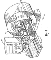
- FIG. 1 illustrates a magnetic resonance imaging scanner 10 for determining internal structure of a subject.
- the scanner 10 includes a housing 12 which encloses a larger encircling magnet for creating a high strength uniform magnetic field over a region of interest.
- Gradient field are created by one or more gradient coils also mounted within the housing 12. The shape and positioning of these coils is such that a gradient field can be superimposed upon the static field in any desired orientation.
- the housing 12 defines an opening 18 into which a subject is inserted for magnet resonance scanning.
- Figure 1 illustrates an rf pulse coil 20 for superimposing a perturbing field onto the high strength field of the encircling magnet.
- a patient support 22 having a headrest 24 is seen positioned in relation to the coil 20 so that the patient's head rests on the headrest 24.
- the coil 20, patient support 22 and patient are moved into the scanning aperture 18 for magnetic resonance imaging.
- the coil 20 shown in Figure 1 creates an rf magnetic field for realigning magnetic moments within a subject region of interest.
- the coil 20 also measures output signals from structure within the patient. These signals are produced by a response of structure within a patient to the combination of magnetic fields created by the high strength magnet, the gradient coils, and the pulse coil 20. Circuitry coupled to the coil 20 through cabling exiting from the rear of the scanner 10 energizes the pulse coil 20.
- a gradient field is superimposed on the high strength field to obtain sufficient information for imaging of the subject.
- the direction and magnitude of the gradient fields are controlled to obtain this information.
- a suitable gradient coil configuration is illustrated in U.S. Patent No. 4,355,282 to Young et al entitled "Nuclear Magnetic Resonance Systems".
- Figure 4A illustrates an energization waveform used for creating an encoding gradient field at a subject region of interest. When applied to electronics for energizing a gradient coil this signal would in theory produce a magnetic field of the desired amplitude and shape for phase encoding a magnetic imaging sequence. In the presence of conductive components such as the pulse coil 20 and circuitry coupled to the pulse coil, however, eddy currents are induced within the scanning aperture 18. The eddy currents result in magnetic field degradation.
- Figure 4B illustrates a typical gradient field similar to the input energization waveform in Figure 4A yet differing in significant respects.
- the present invention alters the input waveform to produce a modified inputto energize the gradient coils.
- a typical modified input is seen in Figure 4C.
- This input produces an output field similar to the input shown in Figure 4A.
- This signal modification is accomplished by sensing magnetic field effects due to eddy currents within the scanning aperture 18 and modifying the input waveform to produce an output field such as that seen in Figure 4D.
- a circuit 40 for modifying the input waveform (Figure 4A) is shown in Figure 2.
- a waveform at an input 50 is generated by computer and converted to analog form by a digital-to-analog converter (not shown).
- the waveform is typically trapezoidal with amplitude and time duration appropriate to the requirements of the particular magnetic resonance pulse sequence utilized.
- N + 1 unity gain operational amplifier buffers 52 The input 50 is buffered by N + 1 unity gain operational amplifier buffers 52.
- N buffers 52 drive low-pass filters 54 formed from resistor/capacitor pairs.
- the resistors 54r are variable alowing adjustment of filter time constants. The time constants are typical of those generated by eddy current effects.
- Variable gain amplifier buffers 56 having a gain of from 0 to 1 amplify outputs from the filters 54.
- Buffer outputs 55 are coupled to a summing operational amplifier 58 connected in an inverting mode.
- the variable gain amplifiers 56 allow weighting of the various time constants in a summed output.
- the adjustable resistor/capacitor networks emulate the effect of eddy currents on the original waveform.
- the original trapezoidal input is also coupled to an amplifier 52 that drives the gradient coils ("DIRECT OUTPUT").
- the gradient field (ory, orz) is sensed using a search coil 57 ( Figure 1) placed in the cavity 18 with the imaging electronics and coils (gradient and rf) in their scanning position.
- the search coil 57 has 1000 turns of wire with a 20 cm diameter.
- An output from the search coil is integrated to give a field profile.
- a suitable integrator 61 for shaping the search coil output is shown in Figure 3.
- the integrator comprises an operational amplifier 62 with an input 63 and output 64 coupled together by a feedback charging capacitor 65.
- the integrator output 64 is input to one channel of a dual channel oscilloscope 67 ( Figure 1), a summed output 59 ( Figure 2) of the summing amplifier 58 is input to a second channel of this oscilloscope 67.
- the sensitivity (gain) controls are adjusted to give substantially the same amplitude on the oscilloscope display for each input.
- the input 63 from the search coil 57 is used to trigger the sweep rate of the oscilloscope 67 via a one shot 72.
- the calibrated summing amplifier output 59 is fed to a second summing amplifier 66 along with the original amplified waveform "DIRECT OUTPUT". Since the output from the first summing amplifier 58 is a signal opposite in sign to the original input 50, summing these two signals subtracts the RC filtered signal from the original signal to produce a difference signal. This difference signal is then added to the original signal by a third summing amplifier 68. An output 70 of this third summing amplifier 68 is a wavefrom ( Figure 4C) which produces a field profile ( Figure 4D) substantially equivalent to the original input waveform ( Figure 4A).
- the "DIRECT OUTPUT" is used to drive the gradient coils to calibrate the scanner 10.
- the signal labeled "OUTPUT" 70 from the amplfier 68 is used to drive a gradient coil. Since the scanner 10 has coils for producing three mutually orthogonal gradient fields, three calibration tests are required.
Landscapes
- Physics & Mathematics (AREA)
- Condensed Matter Physics & Semiconductors (AREA)
- General Physics & Mathematics (AREA)
- Health & Medical Sciences (AREA)
- General Health & Medical Sciences (AREA)
- Nuclear Medicine, Radiotherapy & Molecular Imaging (AREA)
- Radiology & Medical Imaging (AREA)
- Engineering & Computer Science (AREA)
- Signal Processing (AREA)
- High Energy & Nuclear Physics (AREA)
- Magnetic Resonance Imaging Apparatus (AREA)
Claims (10)
Applications Claiming Priority (2)
| Application Number | Priority Date | Filing Date | Title |
|---|---|---|---|
| US06/758,761 US4703275A (en) | 1985-07-25 | 1985-07-25 | Method and apparatus to compensate for eddy currents in magnetic resonance imaging |
| US758761 | 1985-07-25 |
Publications (2)
| Publication Number | Publication Date |
|---|---|
| EP0215547A1 EP0215547A1 (de) | 1987-03-25 |
| EP0215547B1 true EP0215547B1 (de) | 1990-06-13 |
Family
ID=25053014
Family Applications (1)
| Application Number | Title | Priority Date | Filing Date |
|---|---|---|---|
| EP86304903A Expired EP0215547B1 (de) | 1985-07-25 | 1986-06-25 | Verfahren und Vorrichtung zur Kompensierung von Wirbelströmen in magnetischer Resonanzabbildung |
Country Status (4)
| Country | Link |
|---|---|
| US (1) | US4703275A (de) |
| EP (1) | EP0215547B1 (de) |
| JP (1) | JP2883980B2 (de) |
| DE (1) | DE3671963D1 (de) |
Families Citing this family (38)
| Publication number | Priority date | Publication date | Assignee | Title |
|---|---|---|---|---|
| EP0216523A3 (de) * | 1985-08-27 | 1989-04-05 | Resonex, Inc. | Verfahren zur nichtorthogonalen Bilderzeugung mittels magnetischer Kernresonanz |
| JPS62152444A (ja) * | 1985-12-27 | 1987-07-07 | 株式会社東芝 | 磁気共鳴イメ−ジング装置 |
| JPS63229039A (ja) * | 1987-03-18 | 1988-09-22 | 株式会社東芝 | 磁気共鳴イメ−ジング装置 |
| DE3730148A1 (de) * | 1987-09-09 | 1989-03-30 | Bruker Medizintech | Verfahren zum erzeugen von spin-echo-impulsfolgen mit einem kernspin-tomographen und zur durchfuehrung des verfahrens ausgebildeter kernspin-tomograph |
| EP0307516A1 (de) * | 1987-09-18 | 1989-03-22 | Koninklijke Philips Electronics N.V. | Magnetresonanzabbildungsgerät mit Korrektionssystem für Wirbelströmeeffekte |
| US5121060A (en) * | 1987-11-05 | 1992-06-09 | University Of Queensland | Magnetic field homogenization in NMR spectroscopy |
| JP2541261B2 (ja) * | 1987-12-31 | 1996-10-09 | 株式会社島津製作所 | Mri装置 |
| US4950994A (en) * | 1988-03-07 | 1990-08-21 | General Electric Company | Gradient and polarizing field compensation |
| US4885542A (en) * | 1988-04-14 | 1989-12-05 | The Regents Of The University Of California | MRI compensated for spurious NMR frequency/phase shifts caused by spurious changes in magnetic fields during NMR data measurement processes |
| NL8802212A (nl) * | 1988-09-08 | 1990-04-02 | Philips Nv | Werkwijze en inrichting voor wervelstroomcompensatie in mr apparaten. |
| JPH02264636A (ja) * | 1988-12-23 | 1990-10-29 | Picker Internatl Ltd | 核磁気共鳴方法 |
| US5289128A (en) * | 1992-03-27 | 1994-02-22 | Picker International, Inc. | Superconducting gradient shield coils |
| US4965521A (en) * | 1989-08-11 | 1990-10-23 | Spectroscopy Imaging Systems | Method and apparatus for compensating eddy current effects in a magnetic resonance device having pulsed magnetic field gradients |
| US5313945A (en) * | 1989-09-18 | 1994-05-24 | Noise Cancellation Technologies, Inc. | Active attenuation system for medical patients |
| GB9006320D0 (en) * | 1990-03-21 | 1990-05-16 | Gen Electric Co Plc | Nuclear magnetic resonance apparatus |
| DE4020213C2 (de) * | 1990-06-25 | 1993-10-07 | Siemens Ag | Stromversorgung für eine Gradientenspule eines Kernresonanz-Abbildungssystems |
| EP0476321B1 (de) * | 1990-09-20 | 1996-10-23 | Siemens Aktiengesellschaft | Kernspintomograph |
| JP2551272B2 (ja) * | 1991-07-31 | 1996-11-06 | 株式会社島津製作所 | Mr装置 |
| US5227728A (en) * | 1991-11-01 | 1993-07-13 | The Regents Of The University Of California | Gradient driver control in magnetic resonance imaging |
| JPH05269102A (ja) * | 1991-11-28 | 1993-10-19 | Toshiba Corp | 傾斜磁場アンプ装置 |
| US5349297A (en) * | 1992-03-27 | 1994-09-20 | Picker International Inc. | Combined self shielded gradient coil and shimset |
| US5406204A (en) * | 1992-03-27 | 1995-04-11 | Picker International, Inc. | Integrated MRI gradient coil and RF screen |
| US5530356A (en) * | 1992-07-20 | 1996-06-25 | Kabushiki Kaisha Toshiba | Method and apparatus for generating magnetic fields for nuclear magnetic resonance imaging with cross-talk compensation |
| US5442290A (en) * | 1992-08-04 | 1995-08-15 | The Regents Of The University Of California | MRI gradient drive current control using all digital controller |
| DE4313392C2 (de) * | 1993-04-23 | 1995-06-22 | Siemens Ag | Verfahren zur Kompensation von durch Gradienten verursachten Wirbelströmen bei Kernspinresonanzgeräten |
| JP3537951B2 (ja) * | 1996-03-12 | 2004-06-14 | 株式会社東芝 | 磁気共鳴診断装置 |
| US6127826A (en) * | 1999-01-27 | 2000-10-03 | Picker International, Inc. | EPI image based long term eddy current pre-emphasis calibration |
| DE19947360C1 (de) | 1999-10-01 | 2001-05-03 | Siemens Ag | Verfahren zur Vorgabe einer Sollgröße für ein Gradientenfeld |
| JP2002253532A (ja) | 2000-12-21 | 2002-09-10 | Siemens Ag | 磁気共鳴装置 |
| WO2002052291A1 (en) * | 2000-12-22 | 2002-07-04 | Koninklijke Philips Electronics N.V. | Mri apparatus |
| US7873622B1 (en) * | 2004-09-02 | 2011-01-18 | A9.Com, Inc. | Multi-column search results interface |
| JP2012040362A (ja) * | 2010-07-23 | 2012-03-01 | Toshiba Corp | 磁気共鳴イメージング方法、磁気共鳴イメージング装置およびその制御装置 |
| JP2012183233A (ja) * | 2011-03-07 | 2012-09-27 | Toshiba Corp | 磁気共鳴イメージング装置 |
| DE102011085171B3 (de) * | 2011-10-25 | 2013-03-28 | Siemens Aktiengesellschaft | Regelvorrichtung mit Differenzialsteuerung bei einem magnetisch koppelnden Spulensystem für einen stromgeregelten, die Feldspulen eines Magnetresonanztomographen versorgenden Verstärker |
| US9322892B2 (en) | 2011-12-20 | 2016-04-26 | General Electric Company | System for magnetic field distortion compensation and method of making same |
| US9279871B2 (en) | 2011-12-20 | 2016-03-08 | General Electric Company | System and apparatus for compensating for magnetic field distortion in an MRI system |
| US9274188B2 (en) | 2012-11-30 | 2016-03-01 | General Electric Company | System and apparatus for compensating for magnetic field distortion in an MRI system |
| EP3739353B1 (de) * | 2019-05-15 | 2024-02-28 | Siemens Healthineers AG | Verfahren zur steuerung eines magnetresonanzbildgebungssystems und entsprechendes magnetresonanzbildgebungssystem |
Family Cites Families (15)
| Publication number | Priority date | Publication date | Assignee | Title |
|---|---|---|---|---|
| CH417155A (de) * | 1964-07-23 | 1966-07-15 | Trueb Taeuber & Co Ag | Kernresonanzspektrograph |
| GB1347143A (en) * | 1971-04-16 | 1974-02-27 | Newport Instr Ltd | Checking and calibration of apparatus incorporating a resonance circuit |
| US4005358A (en) * | 1974-10-07 | 1977-01-25 | Simon Foner | Magnetometer with out-of-phase correction |
| GB1584950A (en) * | 1978-05-25 | 1981-02-18 | Emi Ltd | Imaging systems |
| GB1584949A (en) * | 1978-05-25 | 1981-02-18 | Emi Ltd | Imaging systems |
| GB1578910A (en) * | 1978-05-25 | 1980-11-12 | Emi Ltd | Imaging systems |
| US4307344A (en) * | 1979-01-25 | 1981-12-22 | Emi Limited | Imaging systems |
| GB2053481B (en) * | 1979-07-06 | 1983-04-07 | Newport Instr Ltd | Nmr spectrometers |
| US4386318A (en) * | 1980-09-26 | 1983-05-31 | Her Majesty The Queen In Right Of Canada, As Represented By The Minister Of National Defence | Method and apparatus to compensate a gradiometer having first and second unwanted terms |
| US4685468A (en) * | 1983-03-18 | 1987-08-11 | Albert Macovski | NMR imaging system using field compensation |
| US4514691A (en) * | 1983-04-15 | 1985-04-30 | Southwest Research Institute | Baggage inspection apparatus and method for determining presences of explosives |
| GB8331501D0 (en) * | 1983-11-25 | 1984-01-04 | Picker Int Ltd | Nuclear magnetic resonance |
| DE3411222A1 (de) * | 1984-03-27 | 1985-10-10 | Philips Patentverwaltung Gmbh, 2000 Hamburg | Kernspintomograph |
| US4585995A (en) * | 1984-04-19 | 1986-04-29 | Technicare Corporation | Nuclear magnetic resonance eddy field suppression apparatus |
| JPS61235741A (ja) * | 1985-04-12 | 1986-10-21 | Mitsubishi Electric Corp | 核磁気共鳴装置 |
-
1985
- 1985-07-25 US US06/758,761 patent/US4703275A/en not_active Expired - Lifetime
-
1986
- 1986-06-25 DE DE8686304903T patent/DE3671963D1/de not_active Expired - Lifetime
- 1986-06-25 EP EP86304903A patent/EP0215547B1/de not_active Expired
- 1986-07-25 JP JP61175470A patent/JP2883980B2/ja not_active Expired - Fee Related
Also Published As
| Publication number | Publication date |
|---|---|
| EP0215547A1 (de) | 1987-03-25 |
| DE3671963D1 (de) | 1990-07-19 |
| JP2883980B2 (ja) | 1999-04-19 |
| JPS6227932A (ja) | 1987-02-05 |
| US4703275A (en) | 1987-10-27 |
Similar Documents
| Publication | Publication Date | Title |
|---|---|---|
| EP0215547B1 (de) | Verfahren und Vorrichtung zur Kompensierung von Wirbelströmen in magnetischer Resonanzabbildung | |
| US4928063A (en) | Automatic eddy current correction | |
| KR100481740B1 (ko) | 와전류들에의해유도된공간적및시간적으로변화하는자계들을측정하고보상하는방법 | |
| US4761612A (en) | Programmable eddy current correction | |
| EP0332383B1 (de) | Kompensation eines Polarisations- und Gradientenfeldes | |
| JPH0638943A (ja) | 磁気共鳴イメージングシステム及び磁気共鳴イメージング方法 | |
| US7141970B2 (en) | Magnetic resonance imaging device | |
| US4864241A (en) | Long time constant eddy current compensation | |
| EP0395248B1 (de) | Verfahren zur Magnetfeld- und Wirbelstrommessung | |
| JPH0654827A (ja) | 磁気共鳴画像化方法及び装置 | |
| US6043656A (en) | Method for compensating an MRI system for residual magnetization | |
| EP0112663B1 (de) | Magnetische Kernresonanzmethode und Vorrichtung | |
| CA2042148A1 (en) | Method for rapid magnet shimming | |
| KR100747934B1 (ko) | 오차 정량화 방법 및 오차 정량화 시스템 | |
| US4791369A (en) | Method of measuring magnetic field error of an NMR imaging apparatus and of correcting distortion caused by the error | |
| US6211675B1 (en) | Automatic measurement of gradient field distortion | |
| EP0230027B1 (de) | Magnetregelung durch Benutzung der von der Bildgebung der chemischen Verschiebung abgeleiteten Information | |
| GB2193320A (en) | Nmr imaging method | |
| JPH03501090A (ja) | Nmr分光器の磁界均質化方法 | |
| JP2000023943A (ja) | 磁気共鳴方法及び装置 | |
| KR100758084B1 (ko) | 화상 아티팩트 감소 방법 및 화상 아티팩트 최소화 장치 | |
| JPH049414B2 (de) | ||
| JPS6323785B2 (de) | ||
| EP0280930A2 (de) | Apparat und Verfahren zur Bilderzeugung mittels magnetischer Resonanz | |
| Segawa et al. | 5227727 Radio-frequency magnetic field regulating apparatus for magnetic resonance imaging |
Legal Events
| Date | Code | Title | Description |
|---|---|---|---|
| PUAI | Public reference made under article 153(3) epc to a published international application that has entered the european phase |
Free format text: ORIGINAL CODE: 0009012 |
|
| AK | Designated contracting states |
Kind code of ref document: A1 Designated state(s): DE FR GB NL |
|
| 17P | Request for examination filed |
Effective date: 19870623 |
|
| 17Q | First examination report despatched |
Effective date: 19890307 |
|
| GRAA | (expected) grant |
Free format text: ORIGINAL CODE: 0009210 |
|
| AK | Designated contracting states |
Kind code of ref document: B1 Designated state(s): DE FR GB NL |
|
| ET | Fr: translation filed | ||
| REF | Corresponds to: |
Ref document number: 3671963 Country of ref document: DE Date of ref document: 19900719 |
|
| PLBE | No opposition filed within time limit |
Free format text: ORIGINAL CODE: 0009261 |
|
| STAA | Information on the status of an ep patent application or granted ep patent |
Free format text: STATUS: NO OPPOSITION FILED WITHIN TIME LIMIT |
|
| 26N | No opposition filed | ||
| PGFP | Annual fee paid to national office [announced via postgrant information from national office to epo] |
Ref country code: GB Payment date: 19960514 Year of fee payment: 11 |
|
| PG25 | Lapsed in a contracting state [announced via postgrant information from national office to epo] |
Ref country code: GB Free format text: LAPSE BECAUSE OF NON-PAYMENT OF DUE FEES Effective date: 19970625 |
|
| GBPC | Gb: european patent ceased through non-payment of renewal fee |
Effective date: 19970625 |
|
| PGFP | Annual fee paid to national office [announced via postgrant information from national office to epo] |
Ref country code: NL Payment date: 20030513 Year of fee payment: 18 |
|
| PGFP | Annual fee paid to national office [announced via postgrant information from national office to epo] |
Ref country code: DE Payment date: 20040813 Year of fee payment: 19 |
|
| PG25 | Lapsed in a contracting state [announced via postgrant information from national office to epo] |
Ref country code: NL Free format text: LAPSE BECAUSE OF NON-PAYMENT OF DUE FEES Effective date: 20050101 |
|
| NLV4 | Nl: lapsed or anulled due to non-payment of the annual fee |
Effective date: 20050101 |
|
| PGFP | Annual fee paid to national office [announced via postgrant information from national office to epo] |
Ref country code: FR Payment date: 20050628 Year of fee payment: 20 |
|
| PG25 | Lapsed in a contracting state [announced via postgrant information from national office to epo] |
Ref country code: DE Free format text: LAPSE BECAUSE OF NON-PAYMENT OF DUE FEES Effective date: 20060103 |