EP0215370B1 - Kühlmittelausgleichsbehälter, insbesondere für Kraftfahrzeugverbrennungsmotoren - Google Patents
Kühlmittelausgleichsbehälter, insbesondere für Kraftfahrzeugverbrennungsmotoren Download PDFInfo
- Publication number
- EP0215370B1 EP0215370B1 EP86112140A EP86112140A EP0215370B1 EP 0215370 B1 EP0215370 B1 EP 0215370B1 EP 86112140 A EP86112140 A EP 86112140A EP 86112140 A EP86112140 A EP 86112140A EP 0215370 B1 EP0215370 B1 EP 0215370B1
- Authority
- EP
- European Patent Office
- Prior art keywords
- coolant
- expansion tank
- chamber
- coolant expansion
- walls
- Prior art date
- Legal status (The legal status is an assumption and is not a legal conclusion. Google has not performed a legal analysis and makes no representation as to the accuracy of the status listed.)
- Expired - Lifetime
Links
Images

Classifications
-
- F—MECHANICAL ENGINEERING; LIGHTING; HEATING; WEAPONS; BLASTING
- F01—MACHINES OR ENGINES IN GENERAL; ENGINE PLANTS IN GENERAL; STEAM ENGINES
- F01P—COOLING OF MACHINES OR ENGINES IN GENERAL; COOLING OF INTERNAL-COMBUSTION ENGINES
- F01P11/00—Component parts, details, or accessories not provided for in, or of interest apart from, groups F01P1/00 - F01P9/00
- F01P11/02—Liquid-coolant filling, overflow, venting, or draining devices
- F01P11/029—Expansion reservoirs
-
- F—MECHANICAL ENGINEERING; LIGHTING; HEATING; WEAPONS; BLASTING
- F28—HEAT EXCHANGE IN GENERAL
- F28F—DETAILS OF HEAT-EXCHANGE AND HEAT-TRANSFER APPARATUS, OF GENERAL APPLICATION
- F28F2255/00—Heat exchanger elements made of materials having special features or resulting from particular manufacturing processes
- F28F2255/14—Heat exchanger elements made of materials having special features or resulting from particular manufacturing processes molded
- F28F2255/143—Heat exchanger elements made of materials having special features or resulting from particular manufacturing processes molded injection molded
Definitions
- the invention relates to a coolant expansion tank, in particular for motor vehicle internal combustion engines, with at least one filler chamber for receiving coolant and at least one expansion chamber separated from the filler chamber by means of a partition wall, but via a connecting line connected to the expansion chamber.
- Such a coolant expansion tank is known from DE-OS 2 852 725.
- the container is divided into a filling chamber and an expansion chamber by means of a vertically arranged partition.
- the upper area of the filling chamber is connected to the lower area of the expansion chamber via a connecting line.
- the fill chamber is filled with coolant up to a certain height. For example, due to a high operating temperature of the internal combustion engine to be cooled, the coolant is heated and thereby expands. The result of this is that coolant overflows from the filling chamber via the connecting line into the expansion chamber. When the coolant is subsequently cooled, it is drawn back from the expansion chamber into the filling chamber by means of negative pressure.
- the object of the invention is to provide a coolant expansion tank, in particular for motor vehicle internal combustion engines, in which, at the same time as the outer walls of the coolant expansion tank are checked for leaks, the separating wall separating the filling chamber and the expansion chamber from one another can also be checked for leaks.
- the double-walled design of the partition wall means that if the partition wall leaks, the test equipment will leak into the test space formed by the two walls of the double wall. This can be determined by monitoring the test room, so that the tested coolant expansion tank can be identified as leaking in this way. Leakages on the outer wall of the coolant expansion tank can be determined in the same operation by leakage of test equipment at the corresponding point.
- the two walls of the partition are designed to form a test chamber by means of transverse walls. In this way, a closed test chamber is formed.
- the outer walls of this test chamber are aligned with the outer walls of the adjacent replenishment chamber and expansion chamber.
- At least one transverse wall has at least one opening leading outwards. If the partition between the filling chamber and the expansion chamber is leaking, as already described, test equipment enters the test chamber and through the opening to the outside. The leakage of the partition can be recognized by the fact that test equipment emerges from the opening. It is expedient to provide openings of this type on all the outer walls of the test chamber, so that the position of the coolant expansion tank is irrelevant in its leak test.
- a connecting line is arranged between the two walls of the partition wall, which connects the filling chamber and the expansion chamber with each other.
- the connecting line is integrated into the coolant expansion tank through this configuration, which is particularly advantageous for the manufacture and the functional reliability of the coolant expansion tank, on the other hand, by integrating the connecting line between the two walls of the test chamber, it is achieved that during the leak test of the coolant expansion tank and in particular that Partition at the same time the connecting line is checked for leaks. If the connection line is leaking, test equipment emerges from the connection line into the test room, which, as already described, can be determined.
- the coolant expansion tank consists of at least two housing parts which are joined along a parting line forming a parting plane. If the parting plane intersects the partition, the tightness of the parting plane of the parting plane, which cuts the partition, is checked for tightness at the same time as the leakage test of the partition.
- the coolant expansion tank it is therefore not necessary to pay attention to how the parting plane runs, since even if a joint cuts the partition and the possibility of the partition leaking due to a leaking joint is increased, such a leak can be reliably determined.
- coolant expansion tank Another advantage of the coolant expansion tank according to the invention is that the design of the filler chamber and the expansion chamber, the arrangement and design of the walls forming the test room, the design and the course of the connecting line within the test room as well as the position of the parting plane of the two housing halves of the coolant expansion tank are completely arbitrary is selectable. The same che applies to the way in which the coolant expansion tank is manufactured. It is particularly advantageous to produce the coolant expansion tank as an injection molded part made of plastic.
- coolant which has been heated in the cooling jacket of the internal combustion engine, is pumped through a heat exchanger for cooling.
- a coolant expansion tank connected to the pump.
- This has the task of absorbing the volume expansion that occurs due to the heating of the coolant, which u. a. is achieved by dividing the coolant expansion tank into a replenishment chamber and an expansion chamber.
- the coolant expansion tank has the task of making it possible to separate gas bubbles that may have formed from heating from the coolant. This will u. a. thereby achieved that the circulation speed of the coolant through the coolant expansion tank is significantly slower than in the actual cooling circuit, so that the separation of gas bubbles from the coolant can take place within the coolant expansion tank.
- the coolant expansion tank 90 which is provided for installation in a motor vehicle.
- the installation position of the coolant expansion tank 90 in the motor vehicle corresponds to the position shown in FIG. 1.
- the coolant expansion tank 90 consists essentially of a filling chamber 10 and an expansion chamber 11, which are connected to one another via a connecting line 13.
- the filling chamber 10 is arranged in the right area of the coolant expansion tank 90, while the expansion chamber 11 is in the left area.
- the connecting line 13 is provided in the middle of the coolant expansion tank 90 and has an S-shaped shape.
- the long side 71 of the coolant expansion tank 90 shown in FIG. 1 has an essentially elongated rectangular shape. Overall, the coolant expansion tank 90 is essentially a rectangular cuboid.
- a round filler neck 15 is attached obliquely to the right end 40 of the same, which is closed with a removable cover 16.
- two round inlet sockets are arranged one below the other on the front side 40.
- a round suction port 26 is approximately in the middle of the area of the filling chamber 10. This, as well as the inlet connection 25, project perpendicularly from the coolant expansion tank 90 and have a constant diameter.
- Coolant can be filled or refilled into the filling chamber 10 via the filler neck 15, coolant is supplied to the filling chamber 10 from the heat exchanger and / or the cooling jacket of the internal combustion engine via the inlet nozzle 25, and coolant is sucked out of the filling chamber 10 by the pump via the suction nozzle 26 .
- a round valve stub 18 is attached to the top 41 thereof, which is closed, for example, by a cover 19 which can be opened rotatably.
- the valve stub 18 is connected to the expansion chamber 11 so that a pressure valve integrated in the cover 19 opens at a predeterminable pressure in the expansion chamber 11 and coolant emerges from the coolant expansion tank 90 via an overflow line 20 connected to the pressure relief valve until the pressure relief valve due to a pressure reduction closes again.
- the connecting line 13 leads from an upper region 35 of the filling chamber 10 to a lower region 36 of the expansion chamber 11. It is arranged essentially vertically in the center of the coolant expansion tank 90 and via a channel 37 to the above-mentioned upper region 35 and via a channel 38 said lower region 36 connected.
- the channels 37 and 38 run essentially horizontally, which results in the aforementioned S-shape of the connecting line 13.
- the channel 37 is arranged higher than the filling chamber 10. This is achieved in that the outer wall 60 of the channel 37 projects beyond the outside 41 of the coolant expansion tank 90. Analogously to this, the outer wall 61 of the channel 38 is also formed to protrude beyond the underside 42 of the coolant expansion tank 90. This ensures that when the coolant cools, all the coolant can be withdrawn from the expansion chamber 11 into the filling chamber 10 by negative pressure.
- the connecting line 13 is arranged vertically in the middle of the coolant expansion tank 90. Its left outer wall is identified in FIG. 1 with the reference number 51, its right outer wall with 52. Parallel to these two outer walls 51 and 52 of the connecting line 13, two walls 50 and 53 are provided, the wall 50 being the expansion mer 11 on its right side and the wall 53 limits the replenishment chamber 10 on its left side.
- the walls 50 and 51 and the walls 52 and 53 are each connected to one another. As a result, the walls 50 and 51 enclose a test room section 55 of a test chamber 58 and the walls 52 and 53 enclose a test room section 56 of the test chamber 58.
- the right test chamber section 56 which is adjacent to the filling chamber 10, has an opening 66 at its end adjoining the underside 42 of the coolant expansion tank 90, via which opening it is connected to the outside of the coolant expansion tank 90.
- the test chamber section 55 adjoining the expansion chamber 11 has a corresponding opening 65 at its upper end located on the upper side 41 of the coolant expansion tank 90.
- the coolant expansion tank 90 shown in FIG. 1 consists of two housing halves 45 and 46. These are joined together along a parting line 30.
- the parting line 30 runs horizontally approximately in the middle of the coolant expansion tank 90.
- the parting line 30 divides the filling chamber 10, the expansion chamber 11 and the connecting line 13 each into two parts.
- the parting line 30 is identified by special reference numerals.
- the parting line of the wall 50 is identified by the reference number 80, the wall 51 by the reference number 81, the wall 52 by the reference number 82 and the wall 53 by the reference number 83. All parting lines 30, 80, 81, 82 and 83 are on the division level already mentioned.
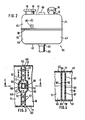
- FIG. 2 shows the view of the left end face 43 of the coolant expansion tank 90 of FIG. 1.
- This end face 43 has a rectangular shape and is formed by the top side 41, the underside 42, the long side 71 visible in FIG. 1 and the long side 70 limited.
- the position of the filler neck 15 in the region of the long side 71, the position of the valve neck 18 adjacent to the long side 70, the position of the inlet neck 25 underneath and the central position of the suction neck 26 can be seen in FIG. 2.
- FIG. 2 also shows the outer walls 60 and 61 of the channels 37 and 38, which protrude beyond the top 41 and bottom 42 of the coolant expansion tank 90.
- the outer walls 60 and 61 do not extend over the entire width of the end face 40, that is to say not from the long side 70 to the long side 71 of the coolant expansion tank 90, but only over a smaller area in the middle of the top 41 and bottom 42.
- FIG. 3 shows the walls 50, 51, 52 and 53 again, which enclose the test space sections 55 and 56. While the walls 51 and 52 are outer walls of the connecting line 13, the walls 50 and 53 extend over the entire width of the coolant expansion tank 90, that is to say from the long side 70 to the long side 71. As a result, the test space sections 55 and 56 unite on both sides of the connecting line 13 to each test chamber section 57 of the test chamber 58.
- the walls 50 and 53 in the area of the connecting line 13 are designed to be arcuate, so that they run parallel to one another outside the connecting line 13.
- the test space section 57 is delimited on the long side 70 of the coolant expansion tank 90 by a wall 62 and on the long side 71 by a wall 63.
- test room section 57 is by a wall 68 and on the upper side 41 by a wall 69 limited. Due to the direction of view of the sectional plane A-A of FIG. 1, the opening 66 of the test room section 56 can be seen in FIG. 3, while the opening 65 of the test room section 55 is located above the drawing plane of FIG. 3.
- FIG. 4 shows the test space section 57 in a section along the plane B-B of FIG. 3.
- 4 corresponds in principle to the partial section of FIG. 1, but in FIG. 1 the partial section has been carried out along a plane intersecting the connecting line 13.
- 4 shows the walls 50 and 53, which enclose the test space section 57, and the two housing halves 45 and 46, which form the parting lines 80 and 83 in the area of the walls 50 and 53.
- openings 77 and 78 are also shown in FIG. 4, which are located in the wall 68 on the underside 42 of the coolant expansion tank 90 and in the wall 69 of the top 41 of the same. Due to the direction of view of the sectional plane B-B of FIG. 3, the openings 77 can also be seen in FIG. 3.
- a test agent is filled into the same, possibly with overpressure. If one of the outer walls of the coolant expansion tank is leaking, the test agent will leak at this point, which means that the leak can be recognized immediately. If, on the other hand, the connecting line 13 or one of the two walls 50 and 53 of the expansion chamber 11 and the filling chamber 10 is leaking, the test medium exits in at least one of the test space sections 55, 56 and 57. From there it passes through at least one of the openings 65, 66, 77 or 78 from the test area sections mentioned and can thus be determined from the outside. The leakage of the connecting line and / or one of the partitions of the coolant expansion tank 90 can thus be recognized. Both checks can be carried out in the same operation. The task of an inspector in this operation is to fill in the inspection equipment and to monitor whether inspection equipment escapes on the outer walls or at the openings of the coolant expansion tank 90.
Landscapes
- Engineering & Computer Science (AREA)
- Chemical & Material Sciences (AREA)
- Combustion & Propulsion (AREA)
- Mechanical Engineering (AREA)
- General Engineering & Computer Science (AREA)
- Heat-Exchange Devices With Radiators And Conduit Assemblies (AREA)
- Filling Or Discharging Of Gas Storage Vessels (AREA)
Description
- Die Erfindung betrifft einen Kühlmittelausgleichsbehälter, insbesondere für Kraftfahrzeugverbrennungsmotoren, mit wenigstens einer Auffüllkammer zur Aufnahme von Kühlmittel und wenigstens einer mittels einer Trennwand von der -Auffüllkammer abgetrennten, aber über eine Verbindungsleitung mit dieser in Verbindung stehenden Ausdehnungskammer.
- Ein derartiger Kühlmittelausgleichsbehälter ist aus der DE-OS 2 852 725 bekannt. Dort ist der Behälter mittels einer senkrecht angeordneten Trennwand in eine Auffüllkammer und eine Ausdehnungskammer aufgeteilt. Der obere Bereich der Auffüllkammer ist über eine Verbindungsleitung mit dem unteren Bereich der Ausdehnungskammer verbunden. Normalerweise ist die Auffüllkammer bis zu einer bestimmten Höhe mit Kühlmittel gefüllt. Beispielsweise aufgrund einer hohen Betriebstemperatur des zu kühlenden Verbrennungsmotors wird das Kühlmittel erhitzt und dehnt sich dadurch aus. Dies hat zur Folge, daß Kühlmittel von der Auffüllkammer über die Verbindungsleitung in die Ausdehnungskammer überläuft. Bei einer nachfolgenden Abkühlung des Kühlmittels wird dieses durch Unterdruck wieder von der Ausdehnungskammer in die Auffüllkammer zurückgezogen. Für die Funktionsfähigkeit eines derartigen Kühlmittelausgleichsbehälters, insbesondere für das Zurückfließen des Kühlmittels von der Ausdehnungskammer in die Auffüllkammer mittels Unterdruck ist es nicht nur wichtig, daß die Außenwände des Kühlmittelausgleichsbehälters dicht sind, sondern es muß auch gewährleistet sein, daß die Trennwand die Ausdehnungskammer und die Auffüllkammer dicht voneinander abtrennt.
- Aufgabe der Erfindung ist es, einen Kühlmittelausgleichsbehälter, insbesondere für Kraftfahrzeugverbrennungsmotoren zu schaffen, bei dem gleichzeitig mit der Überprüfung der Außenwände des Kühlmittelausgleichsbehälters auf deren Dichtigkeit auch die die Auffüllkammer und die Ausdehnungskammer voneinander abtrennende Trennwand auf ihre Dichtigkeit geprüft werden kann.
- Diese Aufgabe wird dadurch gelöst, daß bei einem Kühlmittelausgleichsbehälter der eingangs genannten Art die Trennwand zur Bildung eines überwachbaren Prüfraums doppelwandig ausgebildet ist.
- Diese Ausgestaltung der Trennwand ermöglicht eine Dichtigkeitsprüfung derselben. Wird nämlich zur Dichtigkeitsprüfung des Kühlmittelausgleichsbehälters ein Prüfmittel ggf. unter Druck in den Kühlmittelausgleichsbehälter eingefüllt, so wird durch die doppelwandige Ausführung der Trennwand erreicht, daß bei einer Undichtigkeit der Trennwand in den durch die beiden Wände der Doppelwand gebildeten Prüfraum das Prüfmittel austritt. Dies ist durch die Überwachung des Prüfraums feststellbar, so daß auf diese Weise der geprüfte Kühlmittelausgleichsbehälter als undicht erkannt werden kann. Undichte Stellen der Außenwand des Kühlmittelausgleichsbehälters können dabei in demselben Arbeitsgang durch Austritt von Prüfmittel an der entsprechenden Stelle festgestellt werden.
- In zweckmäßiger Ausgestaltung der Erfindung sind die beiden Wände der Trennwand mittels Querwänden zu einer Prüfkammer gestaltet. Auf diese Weise wird eine geschlossene Prüfkammer gebildet. Bei einer Ausführungsform sind die Außenwände dieser Prüfkammer an die Außenwände der benachbarten Auffüllkammer und Ausdehnungskammer angeglichen.
- Zur Uberwachung der Prüfkammer weist bei einer Weiterbildung der Erfindung wenigstens eine Querwand wenigstens eine nach außen führende Öffnung auf. Ist die Trennwand zwischen Auffüllkammer und Ausdehnungskammer undicht, so gelangt, wie schon beschrieben wurde, Prüfmittel in die Prüfkammer und durch die Öffnung nach außen. Die Undichtigkeit der Trennwand ist also dadurch erkennbar, daß aus der Öffnung Prüfmittel austritt. Zweckmäßig ist es, derartige Öffnungen an sämtlichen Außenwänden der Prüfkammer anzubringen, so daß die Lage des Kühlmittelausgleichsbehälters bei seiner Dichtigkeitsprüfung unerheblich ist.
- In weiterer Ausgestaltung der Erfindung wird vorgesehen, daß zwischen den beiden Wänden der Trennwand eine Verbindungsleitung angeordnet ist, die die Auffüllkammer und die Ausdehnungskammer miteinander verbindet. Einerseits wird durch diese Ausgestaltung die Verbindungsleitung in den Kühlmittelausgleichsbehälter integriert, was insbesondere für die Herstellung und die Funktionssicherheit des Kühlmittelausgleichsbehälters von Vorteil ist, andererseits wird durch die Integration der Verbindungsleitung zwischen die beiden Wände des Prüfraums erreicht, daß bei der Dichtigkeitsprüfung des Kühlmittelausgleichsbehälters und insbesondere der Trennwand gleichzeitig auch die Verbindungsleitung auf ihre Dichtigkeit hin geprüft wird. Ist nämlich die Verbindungsleitung undicht, so tritt Prüfmittel aus der Verbindungsleitung in den Prüfraum aus, was, wie schon beschrieben wurde, feststellbar ist.
- Für die Herstellung des Kühlmittelausgleichsbehälters ist es vorteilhaft, wenn der Kühlmittelausgleichsbehälter aus wenigstens zwei Gehäuseteilen besteht, die längs einer eine Teilungsebene bildenen Trennfuge zusammengefügt sind. Schneidet dabei die Teilungsebene die Trennwand, so wird gleichzeitig mit der Dichtigkeitsprüfung der Trennwand auch die die Trennwand schneidende Trennfuge der Teilungsebene auf ihre Dichtigkeit hin überprüft. Es muß also bei der Konstruktion des Kühlmittelausgleichsbehälters nicht darauf geachtet werden, wie die Teilungsebene verläuft, da selbst dann, wenn eine Trennfuge die Trennwand schneidet und damit die Möglichkeit der Undichtigkeit der Trennwand aufgrund einer undichten Trennfuge erhöht wird, eine derartige Undichtigkeit sicher feststellbar ist.
- Ein weiterer Vorteil des erfindungsgemäßen Kühlmittelausgleichsbehälters besteht darin, daß die Ausgestaltung der Auffüllkammer und der Ausdehnungskammer, die Anordnung und Ausbildung der den Prüfraum bildenden Wände, die Ausgestaltung und der Verlauf der Verbindungsleitung innerhalb des Prüfraums sowie die Lage der Teilungsebene der beiden Gehäusehälften des Kühlmittelausgleichsbehälters völlig beliebig wählbar ist. Das gleiche gilt für die Art und Weise der Herstellung des Kühlmittelausgleichsbehälters. Besonders vorteilhaft ist es, den Kühlmittelausgleichsbehälter als Spritzgußteil aus Kunststoff herzustellen.
- Weitere Merkmale und Vorteile der Erfindung ergeben sich aus den Unteransprüchen sowie aus der nachfolgenden Beschreibung der Zeichnung, in der ein Ausführungsbeispiel dargestellt ist. Es zeigt:
- Fig. 1 eine Seitenansicht eines erfindungsgemäßen Kühlmittelausgleichsbehälters, die teilweise längs der in Fig. 3 gekennzeichneten Ebene C-C aufgeschnitten ist,
- Fig. 2 die Ansicht einer Schmalseite des Kühlmittelausgleichsbehälters der Fig. 1,
- Fig. 3 einen Teilschnitt durch den Kühlmittelausgleichsbehälter der Fig. 1 längs der in Fig. 1 gekennzeichneten Ebene A-A und
- Fig. 4 einen Schnitt durch den Kühlmittelausgleichsbehälter der Fig. 1 längs der in Fig. 3 gekennzeichneten Ebene B-B.
- Bei einem Kühlkreislauf einer Brennkraftmaschine eines Kraftfahrzeugs wird mit Hilfe einer Pumpe Kühlmittel, das im Kühlmantel der Brennkraftmaschine erhitzt worden ist, zur Abkühlung durch einen Wärmetauscher hindurch gepumpt. Zur Erhöhung der Funktionssicherheit ist es bekannt, den Wärmetauscher und ggf. den Kühlmantel der Brennkraftmaschine parallel zum Kühlkreislauf mit einem an die Pumpe angeschlossenen Kühlmittelausgleichsbehälter zu verbinden. Dieser hat die Aufgabe, die aufgrund der Erhitzung des Kühlmittels auftretende Volumenausdehnung desselben aufzufangen, was u. a. durch die Aufteilung des Kühlmittelausgleichsbehälters in eine Auffüllkammer und eine Ausdehnungskammer erreicht wird. Außerdem hat der Kühlmittelausgleichsbehälter die Aufgabe, die Abscheidung von eventuell durch Erhitzung entstandenen Gasblasen aus dem Kühlmittel zu ermöglichen. Dies wird u. a. dadurch erreicht, daß die Umlaufgeschwindigkeit des Kühlmittels über den Kühlmittelausgleichsbehälter wesentlich langsamer ist als im eigentlichen Kühlkreislauf, so daß innerhalb des Kühlmittelausgleichsbehälters die Abscheidung von Gasblasen aus dem Kühlmittel stattfinden kann.
- In der Fig. 1 ist ein Kühlmittelausgleichsbehälter 90 dargestellt, der zum Einbau in ein Kraftfahrzeug vorgesehen ist. Die Einbaulage des Kühlmittelausgleichsbehälters 90 im Kraftfahrzeug entspricht der in der Fig. 1 gezeigten Lage. Der Kühlmittelausgleichsbehälter 90 besteht im wesentlichen aus einer Auffüllkammer 10 und einer Ausdehnungskammer 11, die über eine Verbindungsleitung 13 miteinander verbunden sind. In der Fig. 1 ist die Auffüllkammer 10 im rechten Bereich des Kühlmittelausgleichsbehälters 90 angeordnet, während sich die Ausdehnungskammer 11 im linken Bereich befindet. Die Verbindungsleitung 13 ist in der Mitte des Kühlmittelausgleichsbehälters 90 vorgesehen und besitzt eine S-förmige Gestalt. Die in der Fig. 1 gezeigte Längsseite 71 des Kühlmittelausgleichsbehälters 90 hat eine im wesentlichen länglich rechteckige Form. Insgesamt ist der Kühlmittelausgleichsbehälter 90 im wesentlichen ein rechteckiger Quader.
- An der Oberseite 41 des Kühlmittelausgleichsbehälters 90 ist angrenzend zur rechten Stirnseite 40 desselben ein runder Einfüllstutzen 15 schräg abweisend angebracht, der mit einem abnehmbaren Deckel 16 verschlossen ist. Unterhalb des Einfüllstutzens 15 sind an der Stirnseite 40 zwei runde Zu-- laufstutzen untereinander angeordnet. Auf der Unterseite 42 des Kühlmittelausgleichsbehälters 90 befindet sich schließlich etwa in der Mitte des Bereichs der Auffüllkammer 10 ein runder Absaugstutzen 26. Dieser wie auch die Zulaufstutzen 25 stehen senkrecht vom Kühlmittelausgleichsbehälter 90 ab und besitzen einen gleichbleibenden Durchmesser. Über den Einfüllstutzen 15 kann Kühlmittel in die Auffüllkammer 10 auf- oder nachgefüllt werden, über die Zulaufstutzen 25 wird der Auffüllkammer 10 Kühlmittel vom Wärmetauscher und/oder dem Kühlmantel der Brennkraftmaschine zugeführt und über den Absaugstutzen 26 wird Kühlmittel von der Pumpe aus der Auffüllkammer 10 abgesaugt.
- Im Bereich der linken Stirnseite 43 des Kühlmittelausgleichsbehälters 90 ist auf der Oberseite 41 desselben ein runder Ventilstutzen 18 angebracht, der beispielsweise mit einem drehbar zu öffnenden Deckel 19 verschlossen ist. Der Ventilstutzen 18 ist mit der Ausdehnungskammer 11 verbunden, so daß bei einem vorbestimmbaren Druck in der Ausdehnungskammer 11 ein in den Deckel 19 intregriertes Überdruckventil öffnet und Kühlmittel so lange über eine mit dem Überdruckventil verbundene Überströmleitung 20 aus dem Kühlmittelausgleichsbehälter 90 austritt, bis das Überdruckventil aufgrund einer Druckverringerung wieder schließt.
- Die Verbindungsleitung 13 führt von einem oberen Bereich 35 der Auffüllkammer 10 zu einem unteren Bereich 36 der Ausdehnungskammer 11. Sie ist im wesentlichen senkrecht in der Mitte des Kühlmittelausgleichsbehälters 90 angeordnet und über einen Kanal 37 an den genannten oberen Bereich 35 und über einen Kanal 38 an den genannten unteren Bereich 36 angeschlossen. Die Kanäle 37 und 38 verlaufen im wesentlichen horizontal, wodurch sich die eingangs erwähnte S-Form der Verbindungsleitung 13 ergibt.
- Damit auch bei einer vollständig mit Kühlmittel gefüllten Auffüllkammer eine Gasabscheidung möglich ist, ist der Kanal 37 höher angeordnet als die Auffüllkammer 10. Dies wird dadurch erreicht, daß die Außenwand 60 des Kanals 37 über die Außenseite 41 des Kühlmittelausgleichsbehälters 90 übersteht. Analog dazu ist auch die äußere Wand 61 des Kanals 38 über die Unterseite 42 des Kühlmittelausgleichsbehälters 90 überstehend ausgebildet. Damit wird erreicht, daß bei einer Abkühlung des Kühlmittels sämtliches Kühlmittel aus der Ausdehnungskammer 11 durch Unterdruck in die Auffüllkammer 10 zurückgezogen werden kann.
- Wie schon erwähnt wurde, ist die Verbindungsleitung 13 senkrecht in der Mitte des Kühlmittelausgleichsbehälters 90 angeordnet. Ihre linke Außenwand ist in der Fig. 1 mit der Bezugsziffer 51, ihre rechte Außenwand mit 52 gekennzeichnet. Parallel zu diesen beiden Außenwänden 51 und 52 der Verbindungsleitung 13 sind zwei Wände 50 und 53 vorgesehen, wobei die Wand 50 die Ausdehnungskammer 11 auf ihrer rechten Seite und die Wand 53 die Auffüllkammer 10 auf ihrer linken Seite begrenzt. Die Wände 50 und 51 sowie die Wände 52 und 53 sind jeweils miteinander verbunden. Dadurch schließen die Wände 50 und 51 einen Prüfraumabschnitt 55 einer Prüfkammer 58 und die Wände 52 und 53 einen Prüfraumabschnitt 56 der Prüfkammer 58 ein. Der zur Auffüllkammer 10 benachbarte rechte Prüfraumabschnitt 56 besitzt an seinem an die Unterseite 42 des Kühlmittelausgleichsbehälters 90 angrenzenden Ende eine Öffnung 66, über die er mit dem Außenraum des Kühlmittelausgleichsbehälters 90 verbunden ist. Analog dazu weist der an die Ausdehnungskammer 11 angrenzende Prüfraumabschnitt 55 an seinem an der Oberseite 41 des Kühlmittelausgleichsbehälters 90 befindlichen oberen Ende eine entsprechende Öffnung 65 auf.
- Der in der Fig. 1 dargestellte Kühlmittelausgleichsbehälter 90 besteht aus zwei Gehäusehälften 45 und 46. Diese sind längs einer Trennfuge 30 zusammengefügt. Die Trennfuge 30 verläuft dabei horizontal etwa in der Mitte des Kühlmittelausgleichsbehälters 90. Die Trennfuge 30 teilt die Auffüllkammer 10, die Ausdehnungskammer 11 und die Verbindungsleitung 13 jeweils in zwei Teile.
- Im Bereich der Verbindungsleitung 13 und der Prüfraumabschnitte 55 und 56 ist die Trennfuge 30 durch besondere Bezugsziffern gekennzeichnet. So ist die Trennfuge der Wand 50 mit der Bezugsziffer 80, der Wand 51 mit der Bezugsziffer 81, der Wand 52 mit der Bezugsziffer 82 und der Wand 53 mit der Bezugsziffer 83 ausgezeichnet. Sämtliche Trennfugen 30, 80, 81, 82 und 83 liegen dabei auf der schon erwähnten Teilungsebene.
- Die Fig. 2 zeigt die Ansicht auf die linke Stirnseite 43 des Kühlmittelausgleichsbehälters 90 der Fig. 1. Diese Stirnseite 43 besitzt eine rechteckige Form und ist durch die Oberseite 41, die Unterseite 42, die in der Fig. 1 sichtbare Längsseite 71 und die Längsseite 70 begrenzt. Weiter ist in der Fig. 2 die Lage des Einfüllstutzens 15 im Bereich der Längsseite 71, die Lage des Ventilstutzens 18 angrenzend an die Längsseite 70, die Lage der darunterliegenden Zulaufstutzen 25 und die mittige Lage des Absaugstutzens 26 erkennbar. Schließlich sind der Fig. 2 auch nochmals die Außenwände 60 und 61 der Kanäle 37 und 38 zu entnehmen, die über die Oberseite 41 bzw. Unterseite 42 des Kühlmittelausgleichsbehälters 90 überstehen. Dabei erstrecken sich die Außenwände 60 und 61 nicht über die gesamte Breite der Stirnseite 40, also nicht von der Längsseite 70 zur Längsseite 71 des Kühlmittelausgleichsbehälters 90, sondern nur über einen kleineren Bereich in der Mitte der Oberseite 41 bzw. Unterseite 42.
- In der Fig. 3 sind nochmals die Wände 50, 51, 52 und 53 dargestellt, die die Prüfraumabschnitte 55 und 56 einschließen. Während die Wände 51 und 52 Außenwände der Verbindungsleitung 13 sind, erstrecken sich die Wände 50 und 53 über die gesamte Breite des Kühlmittelausgleichsbehälters 90, also von der Längsseite 70 zur Längsseite 71. Dadurch vereinigen sich die Prüfraumabschnitte 55 und 56 auf beiden Seiten der Verbindungsleitung 13 zu je einem Prüfraumabschnitt 57 der Prüfkammer 58. Zu diesem Zweck sind die Wände 50 und 53 im Bereich der Verbindungsleitung 13 bogenförmig ausgestaltet, so daß sie außerhalb der Verbindungsleitung 13 parallel zueinander verlaufen. Begrenzt wird der Prüfraumabschnitt 57 auf der Längsseite 70 des Kühlmittelausgleichsbehälters 90 durch eine Wand 62 und auf der Längsseite 71 durch eine Wand 63. An der Unterseite 42 des Kühlmittelausgleichsbehälters 90 ist der Prüfraumabschnitt 57 durch eine Wand 68 und an der Oberseite 41 durch eine Wand 69 begrenzt. Aufgrund der Blickrichtung auf die Schnittebene A-A der Fig. 1 ist in der Fig. 3 die Öffnung 66 des Prüfraumabschnitts 56 zu erkennen, während sich die Öffnung 65 des Prüfraumabschnitts 55 über der Zeichenebene der Fig. 3 befindet.
- In der Fig. 4 ist der Prüfraumabschnitt 57 in einem Schnitt längs der Ebene B-B der Fig. 3 dargestellt. Damit entspricht die Fig. 4 im Prinzip dem Teilschnitt der Fig. 1, wobei jedoch in der Fig. 1 der Teilschnitt längs einer die Verbindungsleitung 13 schneidenden Ebene durchgeführt worden ist. Der Fig. 4 sind nochmals die Wände 50 und 53, die den Prüfraumabschnitt 57 einschließen, zu entnehmen, sowie die beiden Gehäusehälften 45 und 46, die im Bereich der Wände 50 und 53 die Trennfugen 80 und 83 bilden. Schließlich sind in der Fig. 4 noch Öffnungen 77 und 78 dargestellt, die sich in der Wand 68 an der Unterseite 42 des Kühlmittelausgleichsbehälters 90 und in der Wand 69 der Oberseite 41 desselben befinden. Aufgrund der Blickrichtung auf die Schnittebene B-B der Fig. 3 sind die Öffnungen 77 auch in der Fig. 3 zu erkennen.
- Zur Überprüfung der Dichtigkeit des beschriebenen Kühlmittelausgleichsbehälters 90 wird ein Prüfmittel ggf. mit Überdruck in denselben eingefüllt. Ist eine der Außenwände des Kühlmittelausgleichsbehälters undicht, so tritt an dieser Stelle das Prüfmittel aus, wodurch die Undichtigkeit sofort erkennbar ist. Ist hingegen die Verbindungsleitung 13 oder eine der beiden Wände 50 und 53 der Ausdehnungskammer 11 und der Auffüllkammer 10 undicht, so tritt das Prüfmittel in wenigstens einen der Prüfraumabschnitte 55, 56 und 57 aus. Von dort gelangt es durch wenigstens eine der Öffnungen 65, 66, 77 oder 78 aus den genannten Prüfraumabschnitten hinaus und ist damit von außen feststellbar. Damit ist die Undichtigkeit der Verbindungsleitung und/oder einer der Trennwände des Kühlmittelausgleichsbehälters 90 erkennbar. Beide Überprüfungen können in demselben Arbeitsgang durchgeführt werden. Die Aufgabe eines Prüfers bei diesem Arbeitsgang besteht darin, das Prüfmittel einzufüllen und zu überwachen, ob Prüfmittel an den Außenwänden oder an den Öffnungen des Kühlmittelausgleichsbehälters 90 austritt.
Claims (6)
Applications Claiming Priority (2)
| Application Number | Priority Date | Filing Date | Title |
|---|---|---|---|
| DE3533095 | 1985-09-17 | ||
| DE19853533095 DE3533095A1 (de) | 1985-09-17 | 1985-09-17 | Kuehlmittelausgleichsbehaelter, insbesondere fuer kraftfahrzeugverbrennungsmotoren |
Publications (3)
| Publication Number | Publication Date |
|---|---|
| EP0215370A2 EP0215370A2 (de) | 1987-03-25 |
| EP0215370A3 EP0215370A3 (en) | 1988-07-06 |
| EP0215370B1 true EP0215370B1 (de) | 1990-03-14 |
Family
ID=6281157
Family Applications (1)
| Application Number | Title | Priority Date | Filing Date |
|---|---|---|---|
| EP86112140A Expired - Lifetime EP0215370B1 (de) | 1985-09-17 | 1986-09-02 | Kühlmittelausgleichsbehälter, insbesondere für Kraftfahrzeugverbrennungsmotoren |
Country Status (4)
| Country | Link |
|---|---|
| US (1) | US4739730A (de) |
| EP (1) | EP0215370B1 (de) |
| BR (1) | BR8604421A (de) |
| DE (2) | DE3533095A1 (de) |
Families Citing this family (28)
| Publication number | Priority date | Publication date | Assignee | Title |
|---|---|---|---|---|
| SE469140B (sv) * | 1991-09-20 | 1993-05-17 | Volvo Ab | Anordning vid kombinerat magasin (16) och expansionskaerl (19) foer en vaetskefyld foerbraenningsmotors kylsystem |
| DE4228856B4 (de) * | 1992-08-29 | 2004-07-22 | Deutz Ag | Flüssigkeitsgekühlte Brennkraftmaschine |
| DE4231846C2 (de) * | 1992-09-23 | 1995-04-13 | Bayerische Motoren Werke Ag | Verdampfungskühlsystem für eine Brennkraftmaschine |
| US5680833A (en) * | 1996-12-23 | 1997-10-28 | Chrysler Corporation | Combination coolant deaeration and overflow bottle |
| US6176205B1 (en) | 1999-04-01 | 2001-01-23 | Daimlerchrysler Corporation | Pressurization of the engine cooling system |
| US6708653B2 (en) * | 2001-04-27 | 2004-03-23 | Bombardier Recreational Products Inc. | Fluid reservoir |
| EP1260685B1 (de) * | 2001-05-23 | 2006-08-09 | Mann + Hummel GmbH | Behälter für das Kühlmittel einer Brennkraftmaschine |
| GB0318402D0 (en) * | 2003-08-06 | 2003-09-10 | Ford Global Tech Llc | Cooling system expansion tank |
| US7343884B1 (en) * | 2006-09-13 | 2008-03-18 | Cummins Power Generation Inc. | Coolant system for hybrid power system |
| US20080060370A1 (en) * | 2006-09-13 | 2008-03-13 | Cummins Power Generation Inc. | Method of cooling a hybrid power system |
| US7552839B2 (en) * | 2006-09-13 | 2009-06-30 | Cummins Power Generation Inc. | Fluid tank with clip-in provision for oil stick tube |
| US7377237B2 (en) * | 2006-09-13 | 2008-05-27 | Cummins Power Generation Inc. | Cooling system for hybrid power system |
| US8038878B2 (en) * | 2008-11-26 | 2011-10-18 | Mann+Hummel Gmbh | Integrated filter system for a coolant reservoir and method |
| US20100206882A1 (en) * | 2009-02-13 | 2010-08-19 | Wessels Timothy J | Multi chamber coolant tank |
| US20110062163A1 (en) * | 2009-09-16 | 2011-03-17 | Mann+Hummel Gmbh | Multi-layer coolant reservoir |
| DE102013016294A1 (de) * | 2012-10-15 | 2014-04-17 | Mann + Hummel Gmbh | Behälter zur Reduzierung des Lufteintrags in ein Fluid |
| US9186979B2 (en) * | 2012-10-15 | 2015-11-17 | Mann + Hummel Gmbh | Reservoir for reducing aeration of a fluid |
| JP6475000B2 (ja) * | 2014-11-20 | 2019-02-27 | トヨタ自動車株式会社 | ラジエータ用リザーバタンク及びラジエータ構造 |
| DE102016006662A1 (de) | 2016-06-01 | 2017-12-07 | GM Global Technology Operations LLC (n. d. Ges. d. Staates Delaware) | Ausgleichsbehälter für einen Kühlmittelkreislauf eines Kraftfahrzeugs |
| DE102017123385A1 (de) * | 2017-10-09 | 2019-04-11 | Volkswagen Aktiengesellschaft | Kühlsystem für ein Fahrzeug |
| CN112654772B (zh) * | 2018-09-11 | 2022-04-01 | 瓦锡兰芬兰有限公司 | 配备有多发动机集液箱装置的动力设备和船舶 |
| CN109184893B (zh) * | 2018-11-22 | 2021-02-09 | 卡特彼勒S.A.R.L公司 | 发动机冷却系统和用于其中的箱体以及作业机械 |
| DE102019115464A1 (de) * | 2019-06-07 | 2020-12-10 | Volkswagen Aktiengesellschaft | Ausgleichbehälter für einen Fluidkreislauf |
| KR102783402B1 (ko) * | 2019-12-16 | 2025-03-19 | 현대자동차주식회사 | 자동차용 통합 리저버 |
| JP7306288B2 (ja) * | 2020-02-07 | 2023-07-11 | トヨタ車体株式会社 | リザーブタンク |
| US12392275B2 (en) * | 2020-09-28 | 2025-08-19 | Hanon Systems | Water supply module integrated with reservoir tank |
| DE102021102022A1 (de) | 2021-01-29 | 2022-08-04 | HELLA GmbH & Co. KGaA | Flüssigkeitstank für ein Flüssigkeitssystem eines Fahrzeugs, Flüssigkeitssystem und Fahrzeug |
| US12360001B2 (en) * | 2023-07-28 | 2025-07-15 | Snap-On Incorporated | Pressure testing and refilling devices, systems, and methods |
Family Cites Families (9)
| Publication number | Priority date | Publication date | Assignee | Title |
|---|---|---|---|---|
| BE669258A (de) * | 1965-09-06 | 1966-03-07 | ||
| DE1601229A1 (de) * | 1968-01-26 | 1970-11-26 | Mannesmann Ag | Waermetauscher |
| DE2115271A1 (de) * | 1971-03-30 | 1972-10-26 | Wieland-Werke Ag, 7900 Ulm | Wärmeübertragungsrohr mit Leckanzeige |
| CH532779A (de) * | 1972-07-01 | 1973-01-15 | H Schaerer Max | Verfahren zum Auffinden undichter Stellen eines doppelwandigen Behälters oder Behälterteils und Einrichtung zur Durchführung des Verfahrens |
| DE2852725A1 (de) * | 1978-12-06 | 1980-06-12 | Sueddeutsche Kuehler Behr | Ausgleichsbehaelter fuer kuehlfluessigkeit |
| DE8015573U1 (de) * | 1980-06-12 | 1980-09-11 | Sueddeutsche Kuehlerfabrik Julius Fr. Behr Gmbh & Co Kg, 7000 Stuttgart | Kuehlwasserausgleichsbehaelter |
| FR2499704B1 (fr) * | 1981-02-12 | 1986-08-14 | Valeo | Echangeur de chaleur et son dispositif de boite a eau et vase d'expansion |
| FR2532740B1 (fr) * | 1982-09-03 | 1988-02-05 | Valeo | Echangeur de chaleur, en particulier pour circuit de refroidissement d'un moteur diesel |
| DE3446007C2 (de) * | 1983-12-28 | 1995-09-14 | Valeo | Wasserkasten und Ausdehnungsgefäß für einen Wärmetauscher eines Verbrennungsmotors |
-
1985
- 1985-09-17 DE DE19853533095 patent/DE3533095A1/de not_active Withdrawn
-
1986
- 1986-09-02 DE DE8686112140T patent/DE3669560D1/de not_active Expired - Lifetime
- 1986-09-02 US US06/902,700 patent/US4739730A/en not_active Expired - Lifetime
- 1986-09-02 EP EP86112140A patent/EP0215370B1/de not_active Expired - Lifetime
- 1986-09-16 BR BR8604421A patent/BR8604421A/pt not_active IP Right Cessation
Also Published As
| Publication number | Publication date |
|---|---|
| EP0215370A3 (en) | 1988-07-06 |
| BR8604421A (pt) | 1987-05-12 |
| US4739730A (en) | 1988-04-26 |
| DE3533095A1 (de) | 1987-03-19 |
| EP0215370A2 (de) | 1987-03-25 |
| DE3669560D1 (de) | 1990-04-19 |
Similar Documents
| Publication | Publication Date | Title |
|---|---|---|
| EP0215370A2 (de) | Kühlmittelausgleichsbehälter, insbesondere für Kraftfahrzeugverbrennungsmotoren | |
| EP0215369B1 (de) | Ausgleichsbehälter für Kühlflüssigkeit | |
| DE69829913T2 (de) | Lüfterverkleidung mit integralem Reservebehälter einer Motorkühlvorrichtung | |
| DE69209303T2 (de) | Expansionstank für ein kühlsystem einer brennkraftmaschine | |
| DE2657308C3 (de) | Querstrom-Wärmetauscher, mit einer Mehrzahl im wesentlichen identischer Platten, welche parallele Strömungswege bilden | |
| DE19538239C1 (de) | Kühlmittelführung in einem Kühlkreislauf einer flüssigkeitsgekühlten Brennkraftmaschine | |
| EP2181253A1 (de) | Ölwanne für eine brennkraftmaschine | |
| EP0213414B1 (de) | Betriebsmittelbehälter in Kraftfahrzeugen | |
| EP1878891B1 (de) | Vertikal geteilter Ausgleichbehälter für Kühlflüssigkeit | |
| DE102015119250B4 (de) | Verbrennungsschutzabdeckung, die mit einem unter druck setzbaren kühlmitteltank gekoppelt ist, und unter druck setzbare kühlmitteltankanordnung, die dieselbe aufweist | |
| DE102016200990A1 (de) | Bleisäurebatterie | |
| WO2013174914A1 (de) | Wärmetauscher zum temperieren eines ersten fluids unter verwendung eines zweiten fluids | |
| DE112021004073T5 (de) | Wasserversorgungsmodul mit integriertem vorratsbehälter | |
| DE69100092T2 (de) | Zylindergehaeuse fuer eine maschine mit dampfabfuhr und oelrueckfuehrleitungen. | |
| DE3416235C2 (de) | ||
| DE3013990C2 (de) | ||
| DE2647970A1 (de) | Gas-fluessigkeits-trennvorrichtung | |
| DE69722966T2 (de) | Verlängerter zylinderkopf für eine dieselbrennkraftmaschine ,mit löchern für einspritzeinheiten und brennstoffzufuhr | |
| DE2840813B1 (de) | Kuehler mit vertikalen Kuehlrohren und einer Entlueftungseinrichtung | |
| DE19509002C2 (de) | Thermostatanbaupositionsstruktur | |
| EP0502326B1 (de) | Auslaufsperre als Teil einer Entlüftungsvorrichtung für Kraftstoffbehälter | |
| DE102023203863A1 (de) | Wärmemanagementmodul | |
| DE19830846A1 (de) | Wärmetauscher | |
| DE10059369A1 (de) | Ausgleichsbehälter | |
| DE4106297A1 (de) | Querstromkuehler, insbesondere wasser/luft-kuehler fuer brennkraftmaschinen |
Legal Events
| Date | Code | Title | Description |
|---|---|---|---|
| PUAI | Public reference made under article 153(3) epc to a published international application that has entered the european phase |
Free format text: ORIGINAL CODE: 0009012 |
|
| AK | Designated contracting states |
Kind code of ref document: A2 Designated state(s): DE FR GB IT NL SE |
|
| PUAL | Search report despatched |
Free format text: ORIGINAL CODE: 0009013 |
|
| AK | Designated contracting states |
Kind code of ref document: A3 Designated state(s): DE FR GB IT NL SE |
|
| 17P | Request for examination filed |
Effective date: 19880811 |
|
| 17Q | First examination report despatched |
Effective date: 19881208 |
|
| GRAA | (expected) grant |
Free format text: ORIGINAL CODE: 0009210 |
|
| AK | Designated contracting states |
Kind code of ref document: B1 Designated state(s): DE FR GB IT NL SE |
|
| ITF | It: translation for a ep patent filed | ||
| GBT | Gb: translation of ep patent filed (gb section 77(6)(a)/1977) | ||
| REF | Corresponds to: |
Ref document number: 3669560 Country of ref document: DE Date of ref document: 19900419 |
|
| ET | Fr: translation filed | ||
| RAP2 | Party data changed (patent owner data changed or rights of a patent transferred) |
Owner name: BEHR GMBH & CO. |
|
| NLT2 | Nl: modifications (of names), taken from the european patent patent bulletin |
Owner name: BEHR GMBH & CO. TE STUTTGART, BONDSREPUBLIEK DUITS |
|
| PLBE | No opposition filed within time limit |
Free format text: ORIGINAL CODE: 0009261 |
|
| STAA | Information on the status of an ep patent application or granted ep patent |
Free format text: STATUS: NO OPPOSITION FILED WITHIN TIME LIMIT |
|
| 26N | No opposition filed | ||
| ITTA | It: last paid annual fee | ||
| EAL | Se: european patent in force in sweden |
Ref document number: 86112140.8 |
|
| PGFP | Annual fee paid to national office [announced via postgrant information from national office to epo] |
Ref country code: GB Payment date: 19980828 Year of fee payment: 13 |
|
| PGFP | Annual fee paid to national office [announced via postgrant information from national office to epo] |
Ref country code: FR Payment date: 19980916 Year of fee payment: 13 |
|
| PGFP | Annual fee paid to national office [announced via postgrant information from national office to epo] |
Ref country code: NL Payment date: 19980923 Year of fee payment: 13 |
|
| PG25 | Lapsed in a contracting state [announced via postgrant information from national office to epo] |
Ref country code: GB Free format text: LAPSE BECAUSE OF NON-PAYMENT OF DUE FEES Effective date: 19990902 |
|
| PG25 | Lapsed in a contracting state [announced via postgrant information from national office to epo] |
Ref country code: NL Free format text: LAPSE BECAUSE OF NON-PAYMENT OF DUE FEES Effective date: 20000401 |
|
| GBPC | Gb: european patent ceased through non-payment of renewal fee |
Effective date: 19990902 |
|
| PG25 | Lapsed in a contracting state [announced via postgrant information from national office to epo] |
Ref country code: FR Free format text: LAPSE BECAUSE OF NON-PAYMENT OF DUE FEES Effective date: 20000531 |
|
| NLV4 | Nl: lapsed or anulled due to non-payment of the annual fee |
Effective date: 20000401 |
|
| REG | Reference to a national code |
Ref country code: FR Ref legal event code: ST |
|
| PG25 | Lapsed in a contracting state [announced via postgrant information from national office to epo] |
Ref country code: IT Free format text: LAPSE BECAUSE OF NON-PAYMENT OF DUE FEES;WARNING: LAPSES OF ITALIAN PATENTS WITH EFFECTIVE DATE BEFORE 2007 MAY HAVE OCCURRED AT ANY TIME BEFORE 2007. THE CORRECT EFFECTIVE DATE MAY BE DIFFERENT FROM THE ONE RECORDED. Effective date: 20050902 |
|
| PGFP | Annual fee paid to national office [announced via postgrant information from national office to epo] |
Ref country code: SE Payment date: 20050919 Year of fee payment: 20 |
|
| PGFP | Annual fee paid to national office [announced via postgrant information from national office to epo] |
Ref country code: DE Payment date: 20051005 Year of fee payment: 20 |
|
| EUG | Se: european patent has lapsed |