EP0215220B1 - Seat belt, in particular a 3-point seat belt for vehicles - Google Patents
Seat belt, in particular a 3-point seat belt for vehicles Download PDFInfo
- Publication number
- EP0215220B1 EP0215220B1 EP86109167A EP86109167A EP0215220B1 EP 0215220 B1 EP0215220 B1 EP 0215220B1 EP 86109167 A EP86109167 A EP 86109167A EP 86109167 A EP86109167 A EP 86109167A EP 0215220 B1 EP0215220 B1 EP 0215220B1
- Authority
- EP
- European Patent Office
- Prior art keywords
- guide slot
- seat belt
- belt
- support frame
- seat
- Prior art date
- Legal status (The legal status is an assumption and is not a legal conclusion. Google has not performed a legal analysis and makes no representation as to the accuracy of the status listed.)
- Expired
Links
Images

Classifications
-
- B—PERFORMING OPERATIONS; TRANSPORTING
- B60—VEHICLES IN GENERAL
- B60R—VEHICLES, VEHICLE FITTINGS, OR VEHICLE PARTS, NOT OTHERWISE PROVIDED FOR
- B60R22/00—Safety belts or body harnesses in vehicles
- B60R22/18—Anchoring devices
- B60R22/26—Anchoring devices secured to the seat
-
- B—PERFORMING OPERATIONS; TRANSPORTING
- B60—VEHICLES IN GENERAL
- B60R—VEHICLES, VEHICLE FITTINGS, OR VEHICLE PARTS, NOT OTHERWISE PROVIDED FOR
- B60R22/00—Safety belts or body harnesses in vehicles
- B60R22/18—Anchoring devices
- B60R22/20—Anchoring devices adjustable in position, e.g. in height
-
- B—PERFORMING OPERATIONS; TRANSPORTING
- B60—VEHICLES IN GENERAL
- B60R—VEHICLES, VEHICLE FITTINGS, OR VEHICLE PARTS, NOT OTHERWISE PROVIDED FOR
- B60R22/00—Safety belts or body harnesses in vehicles
- B60R22/18—Anchoring devices
- B60R2022/1818—Belt guides
Definitions
- the invention relates to a seat belt, in particular to a 3-point seat belt for vehicles, airplanes or the like with an oblique shoulder belt, the upper breakpoint of which is formed by a slot guide arranged on a backrest frame of a seat, a lower end of which is inclined to a longitudinal center plane of the seat extending slot guide is further away from this than an upper end and an end belt portion of the oblique shoulder belt cooperates with a retractor.
- the slot guide is formed by a belt eyelet arranged on the backrest frame, from which an end belt section runs vertically downward to a retractor attached to a seat rail.
- a pivotable lever arrangement is provided below the belt eyelet, which interacts with the oblique shoulder belt.
- This arrangement has the disadvantage that the upper stopping point of the oblique shoulder belt cannot be adapted to the different shoulder heights of the respective vehicle occupants, which impairs the ease of use.
- due to the chosen position of the retractor a considerable length of belt is required.
- the object of the invention is to design a seat with an integrated seat belt so that the upper breakpoint of the inclined shoulder belt automatically adjusts itself to a functional position for the respective vehicle occupant with a simple construction.
- the main advantages achieved with the invention are that the type of slot guide and the position of the roll-up device automatically set a functional position of the upper stopping point.
- the S-shaped shape of the slot guide ensures that the sloping shoulder belt remains in a set position (depending on the shoulder height of the respective vehicle occupant). Due to the arrangement of the retractor next to the slot guide, only a small belt length is required.
- the deflection element arranged downstream of the slot guide ensures trouble-free guidance of the belt between the retractor and the slot guide.
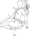
- the seat 1 shown in FIG. 1 for a vehicle, an aircraft or the like comprises a seat part 2 and a backrest 4 which can be pivoted about a horizontal transverse axis 3 and whose upper area forms a fixed headrest 5.
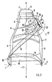
- the backrest 3 essentially consists of a backrest frame 6 and an upholstery 7.
- the backrest frame 6 comprises two spaced-apart side rails 8 which are connected to one another in the region of the headrest 5 via a transverse section 9.
- a lower cross member 10 extends adjacent to the transverse axis 3 between the two side members 8.
- a cross strut 11 is also arranged between the two side members 8 below the headrest 5.
- the side rails 8 are preferably designed as closed box girders and run with a lower region approximately parallel to a longitudinal center plane A-A, whereas in an upper region they are inclined to this plane.
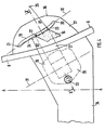
- a seat belt 13 which is designed as a 3-point seat belt according to FIGS. 1 to 3.
- This includes a lap belt 14 and an oblique shoulder belt 15, which have a common lower breakpoint at 16.
- the lap belt 14 runs from the stopping point 16 to a second stopping point 17 arranged at approximately the same height on the other side of the seat part 2.
- the two stopping points 16, 17 are arranged directly on the seat 1 according to FIG. 3. But there is also the possibility that the lower breakpoints 16, 17 are provided on adjacent structural parts.
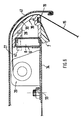
- the sloping shoulder belt 15 extends from the lower tether 16 approximately diagonally to the backrest 4 to the shoulder of the vehicle occupant 12 and from there approximately horizontally to an upper stopping point 18 , in such a way that a lower end 20 of the slot guide 19 is further away from the center longitudinal plane AA than an upper end 21.
- the slot guide 19 has a corresponding width for adaptation to the respective vehicle occupants 12 and is arranged approximately at shoulder height.
- the width of the slot guide 19 corresponds approximately to three times the width of the oblique shoulder belt 15, which provides sufficient adjustment. However, there is also the possibility of making the slot guide 9 even wider.
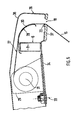
- the slot guide 19, seen in the transverse direction of the vehicle and lying outside the backrest frame 6, has an approximately S-shaped shape according to FIGS. 3 and 5.
- the S-shaped shape of the side 22 of the slot opening 19 which interacts with the webbing 15 is formed by two circular arc sections 23, 24 placed one against the other.
- the center points 25, 26 of the two circular arc sections 23, 24 lie on opposite sides of the slot guide 19.
- the radii R1 and R2 of the two circular arc sections 23 and 24 are approximately the same size (FIG. 4).
- the slot guide 19 can also have a rectilinear or a curved shape (not shown).
- An end-side belt section 27 is guided after the slot guide 19 over a deflection element 28 and interacts with a retractor 29 (FIGS. 5 and 6).
- the deflection element 28 has a circular guide surface 30 for the belt section 27 and is fastened to the backrest frame 6. 1 to 4, the deflection element 28 is not shown.
- the retractor 29 is attached to the backrest frame 6 in such a way that its axis of rotation 31 is approximately aligned with an auxiliary plane 32 penetrating the slot opening 19 in the longitudinal direction. According to FIG. 4, a fastening point 33 of the retractor 29 is arranged adjacent to the longitudinal center plane A-A. To facilitate the adjustment movement of the oblique shoulder belt 15 in the slot guide 19, the retractor 29 is pivotally mounted on a crossbar 34 of the backrest frame 6. The retractor 29 can, however, also be arranged in a fixed manner on the crossbar 34.
- the slot guide 19 is formed on a fitting part 34 which is fastened to the backrest frame 6 in a suitable manner.
- the fitting part 35 is made, for example, of aluminum or a suitable plastic.
- the housing 36 comprises a front part 37, on which the slot guide 19 is provided, and a rear cover 38.
- the slot guide 19 and the deflection element 28 are combined to form a common structural unit 39 which is held in position on the backrest frame 6 by means of fastening screws 40.
- a covering part 41 covers the retractor 29, the belt section 27 and a partial area of the assembly 39.
Description
Die Erfindung bezieht sich auf einen Sicherheitsgurt, insbesondere auf einen 3-Punkt-Sicherheitsgurt für Fahrzeuge, Flugzeuge oder dergleichen mit einem Schrägschultergurt, dessen oberer Haltepunkt durch eine an einem Lehnenrahmen eines Sitzes angeordnete Schlitzführung gebildet wird, wobei ein unteres Ende der schräg zu einer Sitzmittellängsebene verlaufenden Schlitzführung weiter von dieser entfernt ist als ein oberes Ende und ein endseitiger Gurtabschnitt des Schrägschultergurtes mit einer Aufrolleinrichtung zusammenwirkt.The invention relates to a seat belt, in particular to a 3-point seat belt for vehicles, airplanes or the like with an oblique shoulder belt, the upper breakpoint of which is formed by a slot guide arranged on a backrest frame of a seat, a lower end of which is inclined to a longitudinal center plane of the seat extending slot guide is further away from this than an upper end and an end belt portion of the oblique shoulder belt cooperates with a retractor.
Bei einem bekannten Sicherheitsgurt (DE-OS 21 32 709) der eingangs genannten Gattung wird die Schlitzführung durch eine am Lehnenrahmen angeordnete Gurtöse gebildet, von der aus ein endseitiger Gurtabschnitt vertikal nach unten zu einer an einer Sitzschiene befestigten Aufrolleinrichtung verläuft. Zur Erleichterung des Gurtanlegens ist unterhalb der Gurtöse eine schwenkbare Hebelanordnung vorgesehen, die mit dem Schrägschultergurt zusammenwirkt. Dieser Anordnung haftet der Nachteil an, daß der obere Haltepunkt des Schrägschultergurtes nicht an die unterschiedlichen Schulterhöhen der jeweiligen Fahrzeuginsassen anpaßbar ist, was den Bedienungskomfort beeinträchtigt. Außerdem besteht bei dieser Ausführung die Gefahr, daß sich der Gurt infolge der starken Umlenkung nach der Gurtöse in sich verdreht. Ferner ist durch die gewählte Lage der Aufrolleinrichtung eine beträchtliche Gurtlänge erforderlich.In a known seat belt (DE-OS 21 32 709) of the type mentioned, the slot guide is formed by a belt eyelet arranged on the backrest frame, from which an end belt section runs vertically downward to a retractor attached to a seat rail. To make it easier to put on the belt, a pivotable lever arrangement is provided below the belt eyelet, which interacts with the oblique shoulder belt. This arrangement has the disadvantage that the upper stopping point of the oblique shoulder belt cannot be adapted to the different shoulder heights of the respective vehicle occupants, which impairs the ease of use. In addition, in this embodiment there is a risk that the belt will twist due to the strong deflection after the belt eyelet. Furthermore, due to the chosen position of the retractor, a considerable length of belt is required.
Aus der DE-OS 23 45 847 ist ein Kraftfahrzeugsitz mit einem zugeordneten Sicherheitsgurt bekannt, wobei der obere Halte punkt mittels einer Vorrichtung in Höhenrichtung verstellbar ist. Durch die Möglichkeit der individuellen Einstellung des oberen Haltepunktes sind jedoch Fehleinstellungen nicht auszuschließen. Schließlich weist diese Vorrichtung eine Vielzahl von Bauteilen auf, wodurch ihre Herstellung aufwendig und teuer ist.From DE-OS 23 45 847 a motor vehicle seat with an associated seat belt is known, the upper stop point being adjustable in height by means of a device. Due to the possibility of individual adjustment of the upper breakpoint, incorrect settings cannot be ruled out. Finally, this device has a large number of components, which makes its production complex and expensive.
Aufgabe der Erfindung ist es, einen Sitz mit einem integrierten Sicherheitsgurt so auszubilden, daß sich der obere Haltepunkt des Schrägschultergurtes bei einfachem Aufbau für den jeweiligen Fahrzeuginsassen selbsttätig in eine funktionsgerechte Lage einstellt.The object of the invention is to design a seat with an integrated seat belt so that the upper breakpoint of the inclined shoulder belt automatically adjusts itself to a functional position for the respective vehicle occupant with a simple construction.
Erfindungsgemäß wird diese Aufgabe durch die kennzeichnenden Merkmale des Anspruchs 1 gelöst. Weitere, die Erfindung in vorteilhafter Weise ausgestaltende Merkmale beinhalten die Unteransprüche.According to the invention, this object is achieved by the characterizing features of
Die mit der Erfindung hauptsächlich erzielten Vorteile sind darin zu sehen, daß sich durch die Art der Schlitzführung sowie durch die Lage der Aufrolleinrichtung selbsttätig eine funktionsgerechte Lage des oberen Haltepunktes einstellt. Durch den S-förmigen Formverlauf der Schlitzführung wird erreicht, daß der Schrägschultergurt in einer einmal eingestellten Lage (abhängig von der Schulterhöhe des jeweiligen Fahrzeuginsassen) verbleibt. Durch die Anordnung der Aufrolleinrichtung benachbart der Schlitzführung ist nur eine geringe Gurtlänge erforderlich. Das nachfolgend an die Schlitzführung angeordnete Umlenkelement sorgt für eine störungsfreie Führung des Gurtbandes zwischen der Aufrolleinrichtung und der Schlitzführung.The main advantages achieved with the invention are that the type of slot guide and the position of the roll-up device automatically set a functional position of the upper stopping point. The S-shaped shape of the slot guide ensures that the sloping shoulder belt remains in a set position (depending on the shoulder height of the respective vehicle occupant). Due to the arrangement of the retractor next to the slot guide, only a small belt length is required. The deflection element arranged downstream of the slot guide ensures trouble-free guidance of the belt between the retractor and the slot guide.
Ein Ausführungsbeispiel der Erfindung ist in der Zeichnung dargestellt und wird nachfolgend näher erläutert.An embodiment of the invention is shown in the drawing and is explained in more detail below.
Es zeigt
- Fig. 1 eine Schrägansicht von vorne auf einen Sitz mit einem integrierten Sicherheitsgurt,
- Fig. 2 eine Schrägansicht von hinten auf diesen Sitz,
- Fig. 3 eine Vorderansicht eines Lehnenrahmens des Sitzes mit der erfindungsgemäßen Anordnung des Sicherheitsgurtes,
- Fig. 4 eine Einzelheit X der Fig. 3 in größerem Maßstab,
- Fig. 5 einen Schnitt nach der Linie V-V der Fig. 4 in größerem Maßstab,
- Fig. 6 einen Schnitt entsprechend Fig. 5 einer weiteren Ausführungsform.
- 1 is an oblique view from the front of a seat with an integrated seat belt,
- 2 is an oblique view from behind of this seat,
- 3 is a front view of a backrest frame of the seat with the inventive arrangement of the seat belt,
- 4 shows a detail X of FIG. 3 on a larger scale,
- 5 shows a section along the line VV of FIG. 4 on a larger scale,
- Fig. 6 shows a section corresponding to Fig. 5 of a further embodiment.
Der in Fig. 1 dargestellte Sitz 1 für ein Fahrzeug, ein Flugzeug oder dergleichen umfaßt ein Sitzteil 2 und eine, um eine horizontale Querachse 3 schwenkbare Rückenlehne 4, deren oberer Bereich eine feststehende Kopfstütze 5 bildet.The
Die Rückenlehne 3 besteht im wesentlichen aus einem Lehnenrahmen 6 und einer Polsterung 7. Der Lehnenrahmen 6 umfaßt zwei mit Abstand zueinander verlaufende Seitenholme 8, die im Bereich der Kopfstütze 5 über einen Querabschnitt 9 miteinander verbunden sind. Benachbart der Querachse 3 erstreckt sich zwischen den beiden Seitenholmen 8 ein unterer Querträger 10. Unterhalb der Kopfstütze 5 ist ferner eine Querstrebe 11 zwischen den beiden Seitenholmen 8 angeordnet. Die Seitenholme 8 sind vorzugsweise als geschlossene Kastenträger ausgebildet und verlaufen mit einem unteren Bereich etwa parallel zu einer Sitzmittellängsebene A-A, wogegen sie in einem oberen Bereich schräg zu dieser Ebene geneigt sind.The backrest 3 essentially consists of a
Zur Sicherung eines auf dem Sitz 1 befindlichen Fahrzeuginsassen 12 ist ein Sicherheitsgurt 13 vorgesehen, der gemäß den Fig. 1 bis 3 als 3-Punkt-Sicherheitsgurt ausgeführt ist. Dieser umfaßt einen Beckengurt 14 und einen Schrägschultergurt 15, die bei 16 einen gemeinsamen unteren Haltepunkt besitzen. Der Beckengurt 14 verläuft von Haltepunkt 16 zu einem zweiten, etwa in der gleichen Höhe angeordneten Haltepunkt 17 auf der anderen Seite des Sitzteiles 2. Die beiden Haltepunkt 16, 17 sind nach Fig. 3 unmittelbar am Sitz 1 angeordnet. Es besteht aber auch die Möglichkeit, daß die unteren Haltepunkte 16, 17 an angrenzenden Aufbauteilen vorgesehen sind.To secure a
Der Schrägschultergurt 15 erstreckt sich vom unteren Haltegurt 16 etwa diagonal zur Rückenlehne 4 verlaufend zur Schulter des Fahrzeuginsassen 12 und von dort etwa waagrecht zu einem oberen Haltepunkt 18. Dieser wird durch eine am Lehnenrahmen 6 angebrachte Schlitzführung 19 gebildet, die schräg zur Sitzmittellängsebene A-A geneigt ist, dergestalt, daß ein unteres Ende 20 der Schlitzführung 19 weiter von der Sitzmittellängsebene A-A entfernt ist als ein oberes Ende 21.The sloping
Die Schlitzführung 19 weist zur Anpassung an den jeweiligen Fahrzeuginsassen 12 eine entsprechende Breite auf und ist etwa in Schulterhöhe angeordnet. Die Breite der Schlitzführung 19 entspricht etwa der dreifachen Breite des Schrägschultergurtes 15, wodurch eine ausreichende Verstellmöglichkeit gegeben ist. Es besteht jedoch auch die Möglichkeit, die Schlitzführung 9 gegebenenfalls noch breiter auszubilden.The
Die in Fahrzeugquerrichtung gesehen, außerhalb des Lehnenrahmens 6 liegende Schlitzführung 19 weist entsprechend den Fig. 3 und 5 einen annähemd S-förmigen Formverlauf auf. Der S-förmige Formverlauf der mit dem Gurtband 15 zusammenwirkenden Seite 22 der Schlitzöffnung 19 wird durch zwei aneinandergesetzte Kreisbogenabschnitte 23, 24 gebildet. Die Mittelpunkte 25, 26 der beiden Kreisbogenabschnitte 23, 24 liegen auf gegenüberliegenden Seiten der Schlitzführung 19. Im gewählten Aus führungsbeispiel sind die Radien R1 und R2 der beiden Kreisbogenabschnitte 23 und 24 etwa gleich groß (Fig. 4).The
Die Schlitzführung 19 kann aber auch einen geradlinigen oder einen kurvenförmigen Formverlauf aufweisen (nicht dargestellt).The
Ein endseitiger Gurtabschnitt 27 wird nach der Schlitzführung 19 über ein Umlenkelement 28 geführt und wirkt mit einer Aufrolleinrichtung 29 zusammen (Fig. 5 und 6). Das Umlenkelement 28 weist eine kreisförmige Leitfläche 30 für den Gurtabschnitt 27 auf und ist am Lehnenrahmen 6 befestigt. In den Fig. 1 bis 4 ist das Umlenkelement 28 nicht dargestellt.An end-
Die Aufrolleinrichtung 29 ist derart am Lehnenrahmen 6 befestigt, daß seine Drehachse 31 etwa gleichgerichtet ist zu einer die Schlitzöffnung 19 in Längsrichtung durchdringenden Hilfsebene 32. Gemäß Fig. 4 ist ein Befestigungspunkt 33 der Aufrolleinrichtung 29 benachbart der Sitzmittellängsebene A-A angeordnet. Zur Erleichterung der Verstellbewegung des Schrägschultergurtes 15 in der Schlitzführung 19 ist die Aufrolleinrichtung 29 an einer Quertraverse 34 des Lehnenrahmens 6 schwenkbar gelagert. Die Aufrolleinrichtung 29 kann jedoch auch feststehend an der Quertraverse 34 angeordnet sein.The
Entsprechend den Fig. 1 und 2 ist die Schlitzführung 19 an einem Beschlagteil 34 ausgebildet, das in geeigneter Weise am Lehnenrahmen 6 befestigt ist. Das Beschlagteil 35 ist beispielsweise aus Aluminium oder aus einem geeigneten Kunststoff hergestellt.1 and 2, the
Es besteht ferner der Möglichkeit, die Schlitzführung 19 an einem kastenförmigen Gehäuse 36 vorzusehen, das seitlich über den Lehnenrahmen 6 hervorsteht. Das Gehäuse 36 umfaßt ein Vorderteil 37, an dem die Schlitzführung 19 vorgesehen ist, und eine rückwärtige Abdeckung 38.There is also the possibility of providing the
In Fig. 6 ist die Schlitzführung 19 und das Umlenkelement 28 zu einer gemeinsamen Baueinheit 39 zusammengefaßt, die am Lehnenrahmen 6 mittels Befestigungsschrauben 40 in Lage gehalten ist. Ein Verkleidungsteil 41 deckt die Aufrolleinrichtung 29, den Gurtabschnitt 27 und einen Teilbereich der Baueinheit 39 ab.6, the
Claims (7)
Applications Claiming Priority (2)
| Application Number | Priority Date | Filing Date | Title |
|---|---|---|---|
| DE19853530495 DE3530495A1 (en) | 1985-08-27 | 1985-08-27 | SAFETY BELT, ESPECIALLY 3-POINT SAFETY BELT FOR VEHICLES, AIRPLANES OR THE LIKE |
| DE3530495 | 1985-08-27 |
Publications (2)
| Publication Number | Publication Date |
|---|---|
| EP0215220A1 EP0215220A1 (en) | 1987-03-25 |
| EP0215220B1 true EP0215220B1 (en) | 1989-09-06 |
Family
ID=6279410
Family Applications (1)
| Application Number | Title | Priority Date | Filing Date |
|---|---|---|---|
| EP86109167A Expired EP0215220B1 (en) | 1985-08-27 | 1986-07-04 | Seat belt, in particular a 3-point seat belt for vehicles |
Country Status (2)
| Country | Link |
|---|---|
| EP (1) | EP0215220B1 (en) |
| DE (2) | DE3530495A1 (en) |
Families Citing this family (27)
| Publication number | Priority date | Publication date | Assignee | Title |
|---|---|---|---|---|
| JPH0414289Y2 (en) * | 1986-07-22 | 1992-03-31 | ||
| DE3843308A1 (en) * | 1988-12-22 | 1990-06-28 | Autoliv Kolb Gmbh & Co Kg | Seat belt system |
| US5257820A (en) * | 1990-05-16 | 1993-11-02 | Takata Corporation | Slip anchor for seat belt |
| JPH0471355U (en) * | 1990-11-02 | 1992-06-24 | ||
| SE469553B (en) * | 1990-12-06 | 1993-07-26 | Volvo Ab | HIGHLIGHTS COUNTRIES |
| WO1995001892A1 (en) * | 1993-07-06 | 1995-01-19 | Dmitry Alexandrovich Shevtsov | Automatic system for using a vehicle seat belt |
| DE4341119A1 (en) * | 1993-12-02 | 1995-06-08 | Autoliv Dev | Pre-assembled carrier unit for the functional parts of a seat belt system |
| US5556171A (en) * | 1995-02-21 | 1996-09-17 | Trw Vehicle Safety Systems Inc. | Seat belt bezel assembly |
| US5722731A (en) * | 1995-10-25 | 1998-03-03 | Chang; Chung L. | Vehicle seat and seat belt arrangement |
| GB2314003A (en) * | 1996-06-13 | 1997-12-17 | Anthony David Berrington | Seat-belt retractors mounted on seat back. |
| US5733013A (en) * | 1996-11-19 | 1998-03-31 | Trw Vehicle Safety Systems Inc | Vehicle occupant restraint apparatus |
| ITTO980476A1 (en) * | 1998-06-02 | 1999-12-02 | Lear Corp Italia Spa | REAR SEAT OF VEHICLE WITH RETURN ELEMENT OF THE SAFETY BELT ROTABLE IN THE POSITION OF REDUCED OVERALL DIMENSION. |
| DE19838930C1 (en) * | 1998-08-27 | 1999-12-02 | Micro Compact Car Smart Gmbh | Combination of guide for seat belt and car seat back unlocking mechanism |
| DE102005000736A1 (en) * | 2005-01-04 | 2006-07-20 | Isringhausen Gmbh & Co Kg | Height-adjustable deflection device for a three-point belt, vehicle seat with a three-point belt and method for height adjustment of the upper breakpoint of a three-point belt |
| DE102005005888B3 (en) * | 2005-02-09 | 2006-06-22 | Isringhausen Gmbh & Co. Kg | Adjustable belt guide for upper supporting point of three point static belt has guide element over which belt is guided along with fastening element provided for arranging belt guide along backrest of vehicle seating |
| DE102005005889B3 (en) | 2005-02-09 | 2006-08-24 | Isringhausen Gmbh & Co. Kg | Rolling guide for vehicle seat has first roller of disk which is rotatably arranged on pin whose diameter is slightly smaller than diameter of first roller and hardness of disk is larger than hardness of first roller |
| DE102005061541B4 (en) | 2005-12-22 | 2009-08-27 | Magna Seating (Germany) Gmbh | Safety belt fitting for a reversible seat |
| DE102006042673B4 (en) * | 2006-09-12 | 2009-07-23 | Isringhausen Gmbh & Co. Kg | Adjustable belt guide for the upper breakpoint of a three-point belt, backrest for a vehicle seat and method for moving a belt guide |
| FR2920361B1 (en) * | 2007-08-29 | 2009-11-06 | Peugeot Citroen Automobiles Sa | SEAT UNLOCKING ACTUATOR WITH GUIDE HOUSING AND SEAT BELT EXTRACTION, AND CORRESPONDING UNLOCKING DEVICE AND SEAT. |
| DE102007062636B4 (en) * | 2007-12-20 | 2009-10-29 | Keiper Gmbh & Co. Kg | vehicle seat |
| GB2457087A (en) * | 2008-02-04 | 2009-08-05 | Valtra Oy Ab | Vehicle seat |
| GB0817081D0 (en) * | 2008-09-18 | 2008-10-29 | Bentley Motors Ltd | Vehicle seat |
| ES2365341B1 (en) * | 2009-10-16 | 2012-09-14 | Fabricación Asientos Vehículos Industriales, S.A. | GUIDE SYSTEM FOR THE SEAT BELT THAT SUBJECTS TO THE TRAVELERS OF A VEHICLE. |
| DE102010030712A1 (en) | 2010-06-30 | 2012-01-05 | Ford Global Technologies, Llc | Belt arrangement for a seat of a vehicle |
| DE102010052245B3 (en) | 2010-11-23 | 2012-02-16 | Isringhausen Gmbh & Co. Kg | Height-adjustable deflection device for a three-point belt, vehicle seat with a three-point belt and method for height adjustment of the upper breakpoint of a three-point belt |
| WO2013139742A1 (en) | 2012-03-19 | 2013-09-26 | Lazzerini Societa' A Responsabilita' Limitata | A vehicle seat provided with compact fast-installing safety belt system. |
| DE102012010338A1 (en) | 2012-05-25 | 2013-11-28 | Gm Global Technology Operations, Llc | Seat belt arrangement in motor vehicle, has seat belt associated with backrest of vehicle seat, while belt retractor is provided for shoulder belt portion of seat belt, where belt retractor is arranged below upper end of backrest |
Family Cites Families (5)
| Publication number | Priority date | Publication date | Assignee | Title |
|---|---|---|---|---|
| FR1239213A (en) * | 1958-10-29 | 1960-08-19 | Advanced Harness Vehicle Seat | |
| GB1286259A (en) * | 1968-10-31 | 1972-08-23 | Teleflex Ltd Formerly Known As | Improvements in or relating to safety seats for automobiles and aircraft |
| DE2166822B2 (en) * | 1971-07-01 | 1977-06-30 | Ausscheidung aus: 21 32 709 Ford-Werke AG, 500OKoIn | SEAT BELT ATTACHED TO A MOTOR VEHICLE SEAT |
| JPS5245370B2 (en) * | 1972-05-02 | 1977-11-15 | ||
| DE2345847A1 (en) * | 1973-09-12 | 1975-03-27 | Volkswagenwerk Ag | SAFETY DEVICE FOR VEHICLES |
-
1985
- 1985-08-27 DE DE19853530495 patent/DE3530495A1/en not_active Withdrawn
-
1986
- 1986-07-04 EP EP86109167A patent/EP0215220B1/en not_active Expired
- 1986-07-04 DE DE8686109167T patent/DE3665426D1/en not_active Expired
Also Published As
| Publication number | Publication date |
|---|---|
| DE3665426D1 (en) | 1989-10-12 |
| EP0215220A1 (en) | 1987-03-25 |
| DE3530495A1 (en) | 1987-03-05 |
Similar Documents
| Publication | Publication Date | Title |
|---|---|---|
| EP0215220B1 (en) | Seat belt, in particular a 3-point seat belt for vehicles | |
| DE4316930C2 (en) | Seat for motor vehicles, in particular mobile homes | |
| EP0235383B1 (en) | Impact protection device for the occupants of a motor vehicle | |
| DE3940839C1 (en) | ||
| DE3242593C2 (en) | Height adjustment device for a motor vehicle seat belt | |
| DE3216015A1 (en) | ANCHORING FOR THE BELT CLOSURE OF A SAFETY BELT | |
| EP0895889B2 (en) | Convertible vehicle | |
| DE3613830A1 (en) | Adjustable vehicle seat having a safety belt system | |
| EP0359962B1 (en) | Seat, particularly a motor car seat | |
| DE2303222B2 (en) | Seat belt system for the occupant of a vehicle | |
| DE2820589C2 (en) | Seat belt attachment for a longitudinally adjustable motor vehicle seat | |
| DE3426207A1 (en) | Device for vertically adjusting an upper holding point of a safety belt system | |
| EP0830972B1 (en) | Child seat with a shell shaped seat part | |
| DE3112458C2 (en) | Step-by-step height-adjustable seat belt deflection in vehicles, in particular motor vehicles | |
| DE19904224C1 (en) | Mechanism to adjust the lower frame position of a vehicle seat has a connecting lever linked to the upper guide frame for dissipation of crash forces evenly into the guide rail | |
| EP0046149B1 (en) | Tarpaulin for a luggage space provision in a passenger car | |
| EP0443110B1 (en) | Safety belt arrangement for the rear seat installation of a motor vehicle | |
| DE2247921A1 (en) | SEAT WITH ADJUSTABLE BACKREST | |
| WO2004076247A1 (en) | Device for fixing a belt lock of a safety belt in a vehicle seat | |
| DE3719656A1 (en) | Safety device for vehicles | |
| DE4320420C2 (en) | Windbreak for a convertible | |
| DE2643818C2 (en) | Passive seat belt system for the occupant of a motor vehicle | |
| DE2931875C2 (en) | Seat belt device for the occupant of a vehicle | |
| DE19843870A1 (en) | Restraint system for child seats mounted on seat part of rear seat bank of vehicle, with first and second child seats spaced out to allow for third one between them | |
| EP1197383B1 (en) | Seat for mounting in automotive vehicles |
Legal Events
| Date | Code | Title | Description |
|---|---|---|---|
| PUAI | Public reference made under article 153(3) epc to a published international application that has entered the european phase |
Free format text: ORIGINAL CODE: 0009012 |
|
| AK | Designated contracting states |
Kind code of ref document: A1 Designated state(s): DE FR GB IT |
|
| 17P | Request for examination filed |
Effective date: 19870723 |
|
| 17Q | First examination report despatched |
Effective date: 19880826 |
|
| ITF | It: translation for a ep patent filed |
Owner name: DE DOMINICIS & MAYER S.R.L. |
|
| GRAA | (expected) grant |
Free format text: ORIGINAL CODE: 0009210 |
|
| AK | Designated contracting states |
Kind code of ref document: B1 Designated state(s): DE FR GB IT |
|
| GBT | Gb: translation of ep patent filed (gb section 77(6)(a)/1977) | ||
| REF | Corresponds to: |
Ref document number: 3665426 Country of ref document: DE Date of ref document: 19891012 |
|
| ET | Fr: translation filed | ||
| PLBE | No opposition filed within time limit |
Free format text: ORIGINAL CODE: 0009261 |
|
| STAA | Information on the status of an ep patent application or granted ep patent |
Free format text: STATUS: NO OPPOSITION FILED WITHIN TIME LIMIT |
|
| 26N | No opposition filed | ||
| ITTA | It: last paid annual fee | ||
| PGFP | Annual fee paid to national office [announced via postgrant information from national office to epo] |
Ref country code: GB Payment date: 19920626 Year of fee payment: 7 |
|
| PGFP | Annual fee paid to national office [announced via postgrant information from national office to epo] |
Ref country code: FR Payment date: 19920629 Year of fee payment: 7 |
|
| PGFP | Annual fee paid to national office [announced via postgrant information from national office to epo] |
Ref country code: DE Payment date: 19920707 Year of fee payment: 7 |
|
| PG25 | Lapsed in a contracting state [announced via postgrant information from national office to epo] |
Ref country code: GB Effective date: 19930704 |
|
| GBPC | Gb: european patent ceased through non-payment of renewal fee |
Effective date: 19930704 |
|
| PG25 | Lapsed in a contracting state [announced via postgrant information from national office to epo] |
Ref country code: FR Effective date: 19940331 |
|
| PG25 | Lapsed in a contracting state [announced via postgrant information from national office to epo] |
Ref country code: DE Effective date: 19940401 |
|
| REG | Reference to a national code |
Ref country code: FR Ref legal event code: ST |
|
| PG25 | Lapsed in a contracting state [announced via postgrant information from national office to epo] |
Ref country code: IT Free format text: LAPSE BECAUSE OF NON-PAYMENT OF DUE FEES;WARNING: LAPSES OF ITALIAN PATENTS WITH EFFECTIVE DATE BEFORE 2007 MAY HAVE OCCURRED AT ANY TIME BEFORE 2007. THE CORRECT EFFECTIVE DATE MAY BE DIFFERENT FROM THE ONE RECORDED. Effective date: 20050704 |