EP0215208B1 - Machine tool - Google Patents
Machine tool Download PDFInfo
- Publication number
- EP0215208B1 EP0215208B1 EP86108856A EP86108856A EP0215208B1 EP 0215208 B1 EP0215208 B1 EP 0215208B1 EP 86108856 A EP86108856 A EP 86108856A EP 86108856 A EP86108856 A EP 86108856A EP 0215208 B1 EP0215208 B1 EP 0215208B1
- Authority
- EP
- European Patent Office
- Prior art keywords
- headstock
- workpiece
- tool
- support
- head
- Prior art date
- Legal status (The legal status is an assumption and is not a legal conclusion. Google has not performed a legal analysis and makes no representation as to the accuracy of the status listed.)
- Expired - Lifetime
Links
Images

Classifications
-
- B—PERFORMING OPERATIONS; TRANSPORTING
- B23—MACHINE TOOLS; METAL-WORKING NOT OTHERWISE PROVIDED FOR
- B23Q—DETAILS, COMPONENTS, OR ACCESSORIES FOR MACHINE TOOLS, e.g. ARRANGEMENTS FOR COPYING OR CONTROLLING; MACHINE TOOLS IN GENERAL CHARACTERISED BY THE CONSTRUCTION OF PARTICULAR DETAILS OR COMPONENTS; COMBINATIONS OR ASSOCIATIONS OF METAL-WORKING MACHINES, NOT DIRECTED TO A PARTICULAR RESULT
- B23Q39/00—Metal-working machines incorporating a plurality of sub-assemblies, each capable of performing a metal-working operation
- B23Q39/04—Metal-working machines incorporating a plurality of sub-assemblies, each capable of performing a metal-working operation the sub-assemblies being arranged to operate simultaneously at different stations, e.g. with an annular work-table moved in steps
- B23Q39/048—Metal-working machines incorporating a plurality of sub-assemblies, each capable of performing a metal-working operation the sub-assemblies being arranged to operate simultaneously at different stations, e.g. with an annular work-table moved in steps the work holder of a work station transfers directly its workpiece to the work holder of a following work station
-
- B—PERFORMING OPERATIONS; TRANSPORTING
- B23—MACHINE TOOLS; METAL-WORKING NOT OTHERWISE PROVIDED FOR
- B23Q—DETAILS, COMPONENTS, OR ACCESSORIES FOR MACHINE TOOLS, e.g. ARRANGEMENTS FOR COPYING OR CONTROLLING; MACHINE TOOLS IN GENERAL CHARACTERISED BY THE CONSTRUCTION OF PARTICULAR DETAILS OR COMPONENTS; COMBINATIONS OR ASSOCIATIONS OF METAL-WORKING MACHINES, NOT DIRECTED TO A PARTICULAR RESULT
- B23Q3/00—Devices holding, supporting, or positioning work or tools, of a kind normally removable from the machine
- B23Q3/155—Arrangements for automatic insertion or removal of tools, e.g. combined with manual handling
- B23Q3/157—Arrangements for automatic insertion or removal of tools, e.g. combined with manual handling of rotary tools
- B23Q3/15706—Arrangements for automatic insertion or removal of tools, e.g. combined with manual handling of rotary tools a single tool being inserted in a spindle directly from a storage device, i.e. without using transfer devices
-
- B—PERFORMING OPERATIONS; TRANSPORTING
- B23—MACHINE TOOLS; METAL-WORKING NOT OTHERWISE PROVIDED FOR
- B23Q—DETAILS, COMPONENTS, OR ACCESSORIES FOR MACHINE TOOLS, e.g. ARRANGEMENTS FOR COPYING OR CONTROLLING; MACHINE TOOLS IN GENERAL CHARACTERISED BY THE CONSTRUCTION OF PARTICULAR DETAILS OR COMPONENTS; COMBINATIONS OR ASSOCIATIONS OF METAL-WORKING MACHINES, NOT DIRECTED TO A PARTICULAR RESULT
- B23Q7/00—Arrangements for handling work specially combined with or arranged in, or specially adapted for use in connection with, machine tools, e.g. for conveying, loading, positioning, discharging, sorting
- B23Q7/04—Arrangements for handling work specially combined with or arranged in, or specially adapted for use in connection with, machine tools, e.g. for conveying, loading, positioning, discharging, sorting by means of grippers
- B23Q7/045—Arrangements for handling work specially combined with or arranged in, or specially adapted for use in connection with, machine tools, e.g. for conveying, loading, positioning, discharging, sorting by means of grippers using a tool holder as a work-transporting gripper
-
- B—PERFORMING OPERATIONS; TRANSPORTING
- B23—MACHINE TOOLS; METAL-WORKING NOT OTHERWISE PROVIDED FOR
- B23Q—DETAILS, COMPONENTS, OR ACCESSORIES FOR MACHINE TOOLS, e.g. ARRANGEMENTS FOR COPYING OR CONTROLLING; MACHINE TOOLS IN GENERAL CHARACTERISED BY THE CONSTRUCTION OF PARTICULAR DETAILS OR COMPONENTS; COMBINATIONS OR ASSOCIATIONS OF METAL-WORKING MACHINES, NOT DIRECTED TO A PARTICULAR RESULT
- B23Q7/00—Arrangements for handling work specially combined with or arranged in, or specially adapted for use in connection with, machine tools, e.g. for conveying, loading, positioning, discharging, sorting
- B23Q7/04—Arrangements for handling work specially combined with or arranged in, or specially adapted for use in connection with, machine tools, e.g. for conveying, loading, positioning, discharging, sorting by means of grippers
- B23Q7/046—Handling workpieces or tools
-
- Y—GENERAL TAGGING OF NEW TECHNOLOGICAL DEVELOPMENTS; GENERAL TAGGING OF CROSS-SECTIONAL TECHNOLOGIES SPANNING OVER SEVERAL SECTIONS OF THE IPC; TECHNICAL SUBJECTS COVERED BY FORMER USPC CROSS-REFERENCE ART COLLECTIONS [XRACs] AND DIGESTS
- Y10—TECHNICAL SUBJECTS COVERED BY FORMER USPC
- Y10T—TECHNICAL SUBJECTS COVERED BY FORMER US CLASSIFICATION
- Y10T483/00—Tool changing
- Y10T483/16—Tool changing with means to transfer work
-
- Y—GENERAL TAGGING OF NEW TECHNOLOGICAL DEVELOPMENTS; GENERAL TAGGING OF CROSS-SECTIONAL TECHNOLOGIES SPANNING OVER SEVERAL SECTIONS OF THE IPC; TECHNICAL SUBJECTS COVERED BY FORMER USPC CROSS-REFERENCE ART COLLECTIONS [XRACs] AND DIGESTS
- Y10—TECHNICAL SUBJECTS COVERED BY FORMER USPC
- Y10T—TECHNICAL SUBJECTS COVERED BY FORMER US CLASSIFICATION
- Y10T483/00—Tool changing
- Y10T483/17—Tool changing including machine tool or component
- Y10T483/1702—Rotating work machine tool [e.g., screw machine, lathe, etc.]
- Y10T483/1726—Direct tool exchange between tool support and matrix
-
- Y—GENERAL TAGGING OF NEW TECHNOLOGICAL DEVELOPMENTS; GENERAL TAGGING OF CROSS-SECTIONAL TECHNOLOGIES SPANNING OVER SEVERAL SECTIONS OF THE IPC; TECHNICAL SUBJECTS COVERED BY FORMER USPC CROSS-REFERENCE ART COLLECTIONS [XRACs] AND DIGESTS
- Y10—TECHNICAL SUBJECTS COVERED BY FORMER USPC
- Y10T—TECHNICAL SUBJECTS COVERED BY FORMER US CLASSIFICATION
- Y10T483/00—Tool changing
- Y10T483/18—Tool transfer to or from matrix
- Y10T483/1873—Indexing matrix
-
- Y—GENERAL TAGGING OF NEW TECHNOLOGICAL DEVELOPMENTS; GENERAL TAGGING OF CROSS-SECTIONAL TECHNOLOGIES SPANNING OVER SEVERAL SECTIONS OF THE IPC; TECHNICAL SUBJECTS COVERED BY FORMER USPC CROSS-REFERENCE ART COLLECTIONS [XRACs] AND DIGESTS
- Y10—TECHNICAL SUBJECTS COVERED BY FORMER USPC
- Y10T—TECHNICAL SUBJECTS COVERED BY FORMER US CLASSIFICATION
- Y10T82/00—Turning
- Y10T82/25—Lathe
- Y10T82/2514—Lathe with work feeder or remover
- Y10T82/2516—Magazine type
Definitions
- This invention relates to machine tools, and more specifically to the transferring of work pieces between a location where the workpieces are stored and a location where the workpieces are to be machined according to the preamble of claim 1.
- It is known from GB-A-1263912 to provide a machine tool comprising a headstock supporting a spindle on which a chuck is supported.
- the headstock is movable between one pallet on which workpieces are stored and another pallet on which tools are provided, so that a workpiece received by the chuck when adjacent to one pallet can be transferred to proximity with the other pallet for machining.
- Such an arrangement has the difficulty that if the machining is to be done by a tool to be provided on the spindle, the chuck has to be removed and a tool has to be provided on the spindle before machining can commence.
- the machine tool comprises a head 10 supported on a first support member or headstock 11 by a spindle 12.
- the spindle 12 is supported for rotation in an arbor 32 and is rotatable by a motor MR12 about an axis 12A.
- the arbor is movable in the direction of the axis 12A, i.e. in the Z-direction, by a motor MZ12.
- the headstock 11 is secured to a bed 13 and is movable relative thereto in the Y-direction by a motor MY11.
- a second support member or table 14 is supported on the bed for movement in the X-direction and is movable in that direction by a motor MX14.
- the head has releasably secured thereto the work holder 15 having a tapered spigot 26 for engagement with the head 10.
- the work holder is operable by a motor M15, acting through an operating rod 29, to grip or release a workpiece 16.
- the table 14 comprises two parts being respectively a machining support 18 and a storage support or magazine 17.
- the magazine 17 supports a plurality of workpiece blanks 16A.
- the support 18 has secured thereto a tool mount 19 to which is secured at least one turning tool 19A, a dividing head 21 operable by motors M21 and supporting a chuck 20 operable by a motor M20 for gripping and releasing a workpiece.
- the support 18 also embodies a tool storage magazine 22 releasably supporting at least one milling tool 23.
- the tool 23 has at one end a milling cutter 25 and at the other end a spigot 24 dimensioned for being gripped by the holder 15.
- the table 14 also contains a holder 27 for reversing a said workpiece end-to-end and operable by a motor M27.
- the table 14 constitutes a common structure for the supports 17,18,22.
- the machine tool is operated by a numerical control system 40 programmed to act on the motors, generally referred to by the letter M, in a predetermined sequence comprising the following operations:
- the system 25 may be programmed to perform a milling operation by moving the head 10 to insert the workpiece 16 into the chuck 20 operating the chuck motor M20 to grip the workpiece, moving the head 10 to the tool 23, operating the holder 15 to grip the tool 23, moving the head 10 to move the tool 23 to the workpiece 16 held in the chuck 20, and rotating the spindle 12 and moving the head 10 to carry out the milling operation.
- Means may be provided for automatically releasing the holder 15 from the head 10 and securing it thereto.
- the motor M15 may be adapted to engage the narrow end of the tapered spigot 26 of the holder 15 and draw the spigot into a receiving socket in the head, the motor acting through the intermediary of the rod 29.
- Apparatus for automatically securing a work holder or a tool holder to a spindle and releasing it therefrom, and further comprising means for automatically operating the work holder to grip and release a workpiece is shown in my/our British Patent Application No. 8206951 and European Patent Application No.83301333.7.
- the tool 23 may be adapted to be released and secured to the head 10 in the same way as the holder 15, the spigot 23 then being tapered in the same way as the spigot 26.
- the system may be programmed to move the head 10 to deposit the holder 15 in a storage socket 28 on the work support 17 and pick up the tool 23 for the latter to take the place of the holder 15 in the head 10.
- an arbor 30 is supported on the headstock 11 for movement toward and away from the table 14 by a motor M30.
- the arbor 30 has at one end a gripper 31 operable by a motor M31 to grip or release a workpiece.
- the workpieces are transferred between the magazine 17 and the chuck 20 by means of the gripper 31, the spindle 12 being used for supporting a tool, e.g. the tool 23, either in the holder 15 or by means of a spigot such as 26.
- the arbor 30 and gripper 31 can be a relative light structure compared to the spindle 12 which has to sustain the machining forces.
- a magazine 117 and a maching support 118 are stationary, and a headstock 111 is movable on a track 113 along the magazine 117 and support 118 for the purpose of transferring workpieces therebetween.
- the magazine 117 can be arranged to include a tray or palette containing the workpieces and being removable from a supporting surface of the magazine.
- the support 118 can be to some extent movable relative to the magazine for the purpose of machining operations. However essentially, i.e.for the purpose of the transfer operation, the magazine and the support 118 are stationary.
Description
- This invention relates to machine tools, and more specifically to the transferring of work pieces between a location where the workpieces are stored and a location where the workpieces are to be machined according to the preamble of claim 1. It is known from GB-A-1263912 to provide a machine tool comprising a headstock supporting a spindle on which a chuck is supported. The headstock is movable between one pallet on which workpieces are stored and another pallet on which tools are provided, so that a workpiece received by the chuck when adjacent to one pallet can be transferred to proximity with the other pallet for machining. Such an arrangement has the difficulty that if the machining is to be done by a tool to be provided on the spindle, the chuck has to be removed and a tool has to be provided on the spindle before machining can commence.
- The above difficulty is reduced or overcome by the invention as claimed herein.
- Preferred embodiments of a machine tool according to this invention will now be described, by way of example, with reference to the accompanying drawings wherein:-
- Fig.1
- is a front elevation of a first embodiment of the machine tool,
- Fig.2
- is a plan view of Fig.1 drawn diagrammatically and to a reduced scaled, and
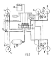
- Fig.3
- is a view similar to Fig.2 but showing a second embodiment.
- Referring to Figs.1 and 2, the machine tool comprises a head 10 supported on a first support member or
headstock 11 by aspindle 12. Thespindle 12 is supported for rotation in an arbor 32 and is rotatable by a motor MR12 about an axis 12A. The arbor is movable in the direction of the axis 12A, i.e. in the Z-direction, by a motor MZ12. Theheadstock 11 is secured to abed 13 and is movable relative thereto in the Y-direction by a motor MY11. A second support member or table 14 is supported on the bed for movement in the X-direction and is movable in that direction by a motor MX14. The head has releasably secured thereto thework holder 15 having a tapered spigot 26 for engagement with the head 10. The work holder is operable by a motor M15, acting through an operating rod 29, to grip or release aworkpiece 16. The table 14 comprises two parts being respectively amachining support 18 and a storage support ormagazine 17. Themagazine 17 supports a plurality of workpiece blanks 16A. Thesupport 18 has secured thereto atool mount 19 to which is secured at least one turning tool 19A, a dividinghead 21 operable by motors M21 and supporting achuck 20 operable by a motor M20 for gripping and releasing a workpiece. Thesupport 18 also embodies atool storage magazine 22 releasably supporting at least onemilling tool 23. Thetool 23 has at one end a milling cutter 25 and at the other end a spigot 24 dimensioned for being gripped by theholder 15. The table 14 also contains a holder 27 for reversing a said workpiece end-to-end and operable by a motor M27. The table 14 constitutes a common structure for thesupports - 1. Moving the head 10 and the
bed 14 relative to one another (motors MY11,MZ12,MX14) to bring theholder 15 into register with one of the blanks 16A in themagazine 17. - 2. Gripping the blank 16A (Motors MZ12,M15).
- 3. Moving the head 10 into proximity with the tool 19A (Motors MY11,MZ12,MX14).
- 4. Rotating the spindle 12 (Motor MR12) to rotate the blank 16A relative to the
tool 19 for a turning operation. - 5. Moving the head and the bed relative to one another (Motors MZ12,MX14) to provide for feed and depth of cut in said turning operation.
- The system 25 may be programmed to perform a milling operation by moving the head 10 to insert the
workpiece 16 into thechuck 20 operating the chuck motor M20 to grip the workpiece, moving the head 10 to thetool 23, operating theholder 15 to grip thetool 23, moving the head 10 to move thetool 23 to theworkpiece 16 held in thechuck 20, and rotating thespindle 12 and moving the head 10 to carry out the milling operation. - Means may be provided for automatically releasing the
holder 15 from the head 10 and securing it thereto. To this end the motor M15 may be adapted to engage the narrow end of the tapered spigot 26 of theholder 15 and draw the spigot into a receiving socket in the head, the motor acting through the intermediary of the rod 29. Apparatus for automatically securing a work holder or a tool holder to a spindle and releasing it therefrom, and further comprising means for automatically operating the work holder to grip and release a workpiece, is shown in my/our British Patent Application No. 8206951 and European Patent Application No.83301333.7. Thetool 23 may be adapted to be released and secured to the head 10 in the same way as theholder 15, thespigot 23 then being tapered in the same way as the spigot 26. The system may be programmed to move the head 10 to deposit theholder 15 in a storage socket 28 on thework support 17 and pick up thetool 23 for the latter to take the place of theholder 15 in the head 10. - In a modification, also shown in Fig. 1, an arbor 30 is supported on the
headstock 11 for movement toward and away from the table 14 by a motor M30. The arbor 30 has at one end a gripper 31 operable by a motor M31 to grip or release a workpiece. In operation, the workpieces are transferred between themagazine 17 and thechuck 20 by means of the gripper 31, thespindle 12 being used for supporting a tool, e.g. thetool 23, either in theholder 15 or by means of a spigot such as 26. The arbor 30 and gripper 31 can be a relative light structure compared to thespindle 12 which has to sustain the machining forces. - In the embodiment shown in Fig. 3, a magazine 117 and a maching support 118 are stationary, and a headstock 111 is movable on a track 113 along the magazine 117 and support 118 for the purpose of transferring workpieces therebetween. The magazine 117 can be arranged to include a tray or palette containing the workpieces and being removable from a supporting surface of the magazine. Also the support 118 can be to some extent movable relative to the magazine for the purpose of machining operations. However essentially, i.e.for the purpose of the transfer operation, the magazine and the support 118 are stationary.
The system 40 is further programmed, on completion of the above turning operation, to return the
Claims (2)
- Machine Tool comprisinga) a headstock (11),b) a spindle provided on the headstock (11),c) first workholding means (15,31) provided on the headstock (11) and operable for gripping or releasing a workpiece (16),d) a machining support (18),e) a storage support (17),f) moving means (13,14,MX14,MY11,MZ12) for relatively moving the headstock (11) between positions respectively adjacent to the storage support (17) and the machining support (18) for transfer of the workpiece (16) therebetween,
characterized in thatg) the first workholding means (31) is provided on the headstock (11) separately from said spindle (12),h) a second workholding means (20) is provided on the machining support (18) and is operable for gripping or releasing the workpiece (16),i) each said workholding means (31,20) is provided with means (M31,M20) for being operated automatically, andj) means (40) is provided for automatically operating each said workholding means (31,20) for said transfer of the work piece (16). - Machine tool according to claim 1 wherein the first workholding means (31) comprise a gripper (31), and automatically operable means (30,M30) supporting the gripper (31) on the headstock (11) for movement in a direction towards and away from the machining support (18).
Applications Claiming Priority (2)
| Application Number | Priority Date | Filing Date | Title |
|---|---|---|---|
| GB8206952 | 1982-03-10 | ||
| GB8206952 | 1982-03-10 |
Related Parent Applications (1)
| Application Number | Title | Priority Date | Filing Date |
|---|---|---|---|
| EP83301334.5 Division | 1983-03-10 |
Publications (3)
| Publication Number | Publication Date |
|---|---|
| EP0215208A2 EP0215208A2 (en) | 1987-03-25 |
| EP0215208A3 EP0215208A3 (en) | 1988-08-10 |
| EP0215208B1 true EP0215208B1 (en) | 1991-04-24 |
Family
ID=10528900
Family Applications (3)
| Application Number | Title | Priority Date | Filing Date |
|---|---|---|---|
| EP86108857A Expired - Lifetime EP0215209B1 (en) | 1982-03-10 | 1983-03-10 | Machine tool |
| EP86108856A Expired - Lifetime EP0215208B1 (en) | 1982-03-10 | 1983-03-10 | Machine tool |
| EP83301334A Expired EP0088645B1 (en) | 1982-03-10 | 1983-03-10 | Machine tool |
Family Applications Before (1)
| Application Number | Title | Priority Date | Filing Date |
|---|---|---|---|
| EP86108857A Expired - Lifetime EP0215209B1 (en) | 1982-03-10 | 1983-03-10 | Machine tool |
Family Applications After (1)
| Application Number | Title | Priority Date | Filing Date |
|---|---|---|---|
| EP83301334A Expired EP0088645B1 (en) | 1982-03-10 | 1983-03-10 | Machine tool |
Country Status (4)
| Country | Link |
|---|---|
| US (2) | US4706371A (en) |
| EP (3) | EP0215209B1 (en) |
| JP (1) | JPS58202744A (en) |
| DE (2) | DE3382564D1 (en) |
Families Citing this family (63)
| Publication number | Priority date | Publication date | Assignee | Title |
|---|---|---|---|---|
| US4545106A (en) * | 1981-04-30 | 1985-10-08 | Gte Valeron Corporation | Machine system using infrared telemetering |
| DE3382564D1 (en) * | 1982-03-10 | 1992-06-25 | Renishaw Plc | MACHINE TOOL. |
| US4608714A (en) * | 1982-09-03 | 1986-08-26 | Gte Valeron Corporation | Low battery detector for a machine system using infrared telemetry |
| DE3409682A1 (en) * | 1984-03-16 | 1985-09-19 | Heyligenstaedt & Co, Werkzeugmaschinenfabrik Gmbh, 6300 Giessen | Method of operating a lathe and device for carrying it out |
| JPS60166010U (en) * | 1984-04-10 | 1985-11-05 | 北川機械工業株式会社 | numerical control machine |
| US4599786A (en) * | 1984-09-04 | 1986-07-15 | Cincinnati Milacron Inc. | Grinding machine with apparatus for changing grinding wheel tools and workpieces |
| JPS6176250A (en) * | 1984-09-24 | 1986-04-18 | Toyoda Mach Works Ltd | Tool changing system by robot |
| DE8526544U1 (en) * | 1985-09-17 | 1987-04-23 | Chiron-Werke Gmbh, 7200 Tuttlingen, De | |
| JPS6268246A (en) * | 1985-09-17 | 1987-03-28 | シロン ベルケ ゲ−エムベ−ハ− | Machine tool device |
| JPS63136844U (en) * | 1987-02-27 | 1988-09-08 | ||
| SE8803729L (en) * | 1988-10-19 | 1990-04-20 | Fixturteknik Ab | SET TO USE A FRAME WITH QUIET TOOLS AND QUESTIONS BEFORE APPLYING THE SET |
| FR2638999B1 (en) * | 1988-11-15 | 1995-02-17 | Musset Claude | PROCESS FOR MANUFACTURING A MODEL AND DEVICE FOR AUTOMATICALLY CUTTING ELEMENTS FOR SUCH MANUFACTURE |
| JPH0352056U (en) * | 1989-09-27 | 1991-05-21 | ||
| DE4022458A1 (en) * | 1990-07-14 | 1992-01-16 | Cross Europa Werk Gmbh | Metal cutting machine tool with automatic work loading - uses compound tool slide fitted with grippers to execute work loading and unloading cycle |
| JPH04109836U (en) * | 1991-03-06 | 1992-09-24 | 三菱自動車工業株式会社 | Machine tool workpiece dispensing device |
| JP2567635Y2 (en) * | 1991-04-08 | 1998-04-02 | トヨタ自動車株式会社 | Transfer equipment for tool change of machine tools |
| US5121539A (en) * | 1991-07-17 | 1992-06-16 | Trumpf Gmbh & Company | Apparatus and method for cutting stacked sheet-like workpieces |
| AU657852B2 (en) * | 1992-04-10 | 1995-03-23 | Emag Holding Gmbh | Machining centre constructed from assemblies |
| DE4212175A1 (en) † | 1992-04-10 | 1993-10-14 | Emag Masch Vertriebs Serv Gmbh | Machining center composed of assemblies |
| DE9205554U1 (en) * | 1992-04-24 | 1993-08-19 | Schiess Kopp Werkzeugmaschinen | Device for metal cutting |
| DE4225509A1 (en) * | 1992-08-01 | 1994-02-03 | Werner Hermann Wera Werke | Machine tool |
| JPH06126573A (en) * | 1992-10-20 | 1994-05-10 | Seki Seisakusho:Kk | Rotary machining device |
| DE4422416C1 (en) * | 1994-06-29 | 1996-01-11 | Magnus Dipl Ing Gruener | Machining center |
| DE19504369A1 (en) * | 1995-02-10 | 1996-08-14 | Index Werke Kg Hahn & Tessky | Multi-spindle machine tool |
| DE19607001C2 (en) * | 1996-02-24 | 1998-05-20 | Chiron Werke Gmbh | Workpiece gripper |
| US5897275A (en) * | 1996-04-30 | 1999-04-27 | Essetre Di Sella Giovanni | Machine tool for machining panels and plates |
| DE19623422C2 (en) * | 1996-06-12 | 2001-11-29 | Chiron Werke Gmbh | Process for machining workpieces on a machine tool |
| US6220799B1 (en) | 1996-07-29 | 2001-04-24 | Matsushita Electric Industrial Co.,Ltd. | Machine tool |
| DE19648810A1 (en) * | 1996-11-26 | 1998-05-28 | Bad Dueben Profilwalzmaschinen | Loading and machining arrangement for lathe |
| US5970599A (en) * | 1997-07-14 | 1999-10-26 | The Olofsson Corporation | Milling machine |
| DE19826507A1 (en) * | 1998-06-15 | 1999-12-16 | Wilfried Taubner | Flexible finishing module for processing workpieces |
| FR2781172B1 (en) * | 1998-07-20 | 2000-10-06 | Renault Automation | MACHINE TOOL, PARTICULARLY MILLING WITH CLOSED STRUCTURE AND ERGONOMIC ARRANGEMENT OF THE FUNCTIONAL PARTS OF SUCH A MACHINE TOOL |
| DE19916977A1 (en) * | 1999-04-15 | 2000-10-19 | Sonja Bonneick | System for machining workpieces |
| DE19919647C2 (en) * | 1999-04-30 | 2003-08-21 | Stama Maschinenfabrik Gmbh | Machine tool with a manipulator |
| DE10005338C2 (en) * | 2000-02-08 | 2002-08-29 | Stama Maschinenfabrik Gmbh | Machine tool and method for machining a workpiece that is clamped using an adapter |
| US6745454B1 (en) * | 2002-01-30 | 2004-06-08 | Hayes Lemmerz International, Inc. | Flexible manufacturing and workpiece transfer system |
| ATE308400T1 (en) * | 2002-02-06 | 2005-11-15 | Danobat | LATHE WITH A PARTS MANIPULATOR |
| DE10224347A1 (en) * | 2002-05-29 | 2003-12-11 | Emag Maschfab Gmbh | Machine tool with swiveling workpiece spindle |
| DE10224952B4 (en) * | 2002-06-05 | 2009-05-07 | Boehringer Werkzeugmaschinen Gmbh | Machine tool with loader |
| DE10307977C5 (en) * | 2003-02-24 | 2012-04-05 | Emag Holding Gmbh | Method and device for processing differential housings |
| US6935003B2 (en) * | 2003-02-28 | 2005-08-30 | National University Of Singapore | Compound fabrication process and apparatus |
| US6832433B2 (en) * | 2003-03-03 | 2004-12-21 | Rockford Products Corporation | Machining apparatus and method of using same |
| DE10354706C5 (en) * | 2003-11-22 | 2009-06-25 | Emag Holding Gmbh | Machine tool with transport device |
| DE102004006757B4 (en) * | 2004-02-06 | 2006-10-19 | Steinhilber, Hektor | machine tool |
| DE102004050035A1 (en) * | 2004-07-09 | 2006-01-26 | Ex-Cell-O Gmbh | Machine tool and method for tool change on a machine tool |
| US7270592B2 (en) * | 2004-08-12 | 2007-09-18 | D4D Technologies, Llc | Milling machine |
| FR2874525B1 (en) * | 2004-09-01 | 2008-01-25 | Oger Soc Par Actions Simplifie | INSTALLATION FOR MACHINING BY DIGITAL CONTROL OF PARTS |
| FR2874524B1 (en) * | 2004-09-01 | 2006-11-24 | Oger Soc Par Actions Simplifie | MACHINING CENTER WITH DIGITAL CONTROL AND INSTALLATION INCORPORATING SUCH A CENTER |
| EP1634677A1 (en) * | 2004-09-10 | 2006-03-15 | VIGEL S.p.A. | Workpiece-machining apparatus with a workpiece gripping tool on the spindle head |
| DE102005030306B3 (en) * | 2005-06-23 | 2007-02-22 | Steinhilber, Hektor | Transfer unit for sequential machining and handling of workpieces has adjustable double grip for workpiece fixed in center of multi-spindle tool head |
| DE102007030955B4 (en) * | 2007-07-04 | 2009-04-09 | The Gleason Works | Method and device for machining workpieces rotating about a workpiece axis |
| US20090293688A1 (en) * | 2008-05-30 | 2009-12-03 | Benedikt Nillies | Metal forming machine and method for spinning/flow forming |
| DE102009027463A1 (en) * | 2009-07-03 | 2011-01-05 | Deckel Maho Pfronten Gmbh | Method and machine tool for machining a workpiece |
| US9278416B2 (en) | 2010-09-15 | 2016-03-08 | Steve Simons | Automated loading of work pieces into adverse environments associated with milling machines |
| US9278415B1 (en) | 2010-09-15 | 2016-03-08 | Steve Simons | Controllers and methods of automated loading of work pieces into adverse environments associated with milling machines |
| DE102016201016A1 (en) * | 2016-01-25 | 2017-07-27 | Deckel Maho Pfronten Gmbh | MACHINE TOOL, PARTICULARLY MULTI-SPINDLE MILLING MACHINE |
| DE102016201018A1 (en) * | 2016-01-25 | 2017-07-27 | Deckel Maho Pfronten Gmbh | MACHINE TOOL, PARTICULARLY MULTI-SPINDLE MILLING MACHINE |
| JP6694226B2 (en) * | 2016-02-22 | 2020-05-13 | ダイハツ工業株式会社 | Machining center |
| JP6787688B2 (en) * | 2016-05-16 | 2020-11-18 | オークマ株式会社 | Machine Tools |
| CN111727097B (en) * | 2018-05-01 | 2024-01-23 | 哈如技术研究所股份有限公司 | Differential case processing machine |
| USD924948S1 (en) * | 2019-10-29 | 2021-07-13 | Walter Meier (Fertigungslösungen) AG | Tool changer |
| DE112021001703T5 (en) * | 2020-04-16 | 2023-01-12 | Fanuc Corporation | processing of a workpiece |
| DE102021117229A1 (en) | 2021-07-05 | 2023-01-05 | Lang Technik Gmbh | Clamping device and method for handling a workpiece |
Family Cites Families (32)
| Publication number | Priority date | Publication date | Assignee | Title |
|---|---|---|---|---|
| US2555963A (en) * | 1946-11-27 | 1951-06-05 | Chrysler Corp | Transmission synchromesh mechanism |
| FR1389246A (en) * | 1963-04-02 | 1965-02-12 | Licentia Gmbh | Tool changing device for numerical controls of machine tools |
| FR1410534A (en) * | 1963-09-09 | 1965-09-10 | Mueller Hellmut Dipl -Ing | Device for machining workpieces, for example drilling device |
| GB1202364A (en) * | 1967-05-05 | 1970-08-19 | David Theodore Nelson Williams | Improvements in or relating to numerically-controlled machine tools |
| GB1263912A (en) * | 1968-03-13 | 1972-02-16 | David Theodore Nelson Williams | Machine tool installations |
| GB1263911A (en) * | 1968-03-13 | 1972-02-16 | David Theodore Nelson Williams | Improvements in or relating to machine tools |
| GB1201869A (en) * | 1968-08-26 | 1970-08-12 | Kavanagh O Moore & Company Ltd | Improved drilling machines |
| US3663998A (en) * | 1969-10-22 | 1972-05-23 | John A Cupler | Apparatus for conducting machining operations |
| US3766617A (en) * | 1971-10-18 | 1973-10-23 | Motch Merryweather Machinery | Workpiece loader and unloader |
| GB1371146A (en) * | 1972-01-28 | 1974-10-23 | Werkzeugmasch Okt Veb | Work-changing devices for machine tools |
| DE2212875C3 (en) * | 1972-03-17 | 1974-09-05 | Schiess Ag, 4000 Duesseldorf-Oberkassel | Device for clamping, loosening and exchanging tool heads on a heavy machine tool |
| US3821835A (en) * | 1972-08-17 | 1974-07-02 | Cincinnati Milacron Heald | Machine tool |
| US4065988A (en) * | 1972-12-04 | 1978-01-03 | Kearney & Trecker Corporation | Unitary work changer for a machining center |
| GB1456385A (en) * | 1973-04-11 | 1976-11-24 | Clarke Chapman Ltd | Mechanical handling equipment |
| SE388554B (en) * | 1973-06-06 | 1976-10-11 | Smt Machine Co Ab | LATHE |
| DE2338207C3 (en) * | 1973-07-27 | 1979-07-05 | Fritz 8102 Mittenwald Petzoldt | Multi-spindle automatic lathe |
| US4019410A (en) * | 1974-03-08 | 1977-04-26 | Rudolf Staszkiewicz | Rotary support for use in a machine tool |
| US4000954A (en) * | 1975-10-31 | 1977-01-04 | Digital Systems, Inc. | Automatic tool changing apparatus for drilling machines and the like |
| CH610797A5 (en) * | 1976-06-08 | 1979-05-15 | Otto Stettler | Machine tool |
| US4090287A (en) * | 1977-01-28 | 1978-05-23 | Kearney & Trecker Corporation | Workpiece changer mechanism for a machine tool |
| US4167362A (en) * | 1977-04-15 | 1979-09-11 | Dietrich Otto E | Multiple tool driving turret attachment |
| JPS5820741B2 (en) * | 1978-10-14 | 1983-04-25 | ファナック株式会社 | Machining center tool change mechanism |
| SE425951B (en) * | 1978-11-13 | 1982-11-29 | Smt Machine Co Ab | DETAIL EXCHANGE AT REPLY |
| JPS5669056A (en) * | 1979-11-08 | 1981-06-10 | Fanuc Ltd | Robot-equipped machining center |
| JPS5733991A (en) * | 1980-08-06 | 1982-02-24 | Fujitsu Fanuc Ltd | Robot hand with chip removing device |
| US4404727A (en) * | 1981-02-24 | 1983-09-20 | Kearney & Trecker Corporation | Machine tool operable as both a chucking type lathe and as a machining center |
| JPS57156142A (en) * | 1981-03-16 | 1982-09-27 | Kitamura Kikai Kk | Automatic exchange method of tool in machining center |
| CA1172877A (en) * | 1981-03-20 | 1984-08-21 | John A. Watson | Boring machine with work handling tool turret |
| CA1193837A (en) * | 1981-06-24 | 1985-09-24 | Tamiaki Matsuura | Automatic assembling machine |
| DE3382564D1 (en) * | 1982-03-10 | 1992-06-25 | Renishaw Plc | MACHINE TOOL. |
| DE3216891A1 (en) * | 1982-05-06 | 1983-11-10 | Index-Werke Kg Hahn & Tessky, 7300 Esslingen | MULTI-SPINDLE REVOLER TURNING MACHINE |
| US4499650A (en) * | 1982-06-24 | 1985-02-19 | Kentner B. Wilson | Automatic tool changer |
-
1983
- 1983-03-10 DE DE8686108857T patent/DE3382564D1/en not_active Expired - Fee Related
- 1983-03-10 EP EP86108857A patent/EP0215209B1/en not_active Expired - Lifetime
- 1983-03-10 JP JP58038401A patent/JPS58202744A/en active Granted
- 1983-03-10 EP EP86108856A patent/EP0215208B1/en not_active Expired - Lifetime
- 1983-03-10 EP EP83301334A patent/EP0088645B1/en not_active Expired
- 1983-03-10 DE DE8686108856T patent/DE3382265D1/en not_active Expired - Fee Related
-
1985
- 1985-12-02 US US06/803,783 patent/US4706371A/en not_active Expired - Lifetime
-
1987
- 1987-06-23 US US07/065,564 patent/US4947538A/en not_active Expired - Fee Related
Also Published As
| Publication number | Publication date |
|---|---|
| EP0088645A1 (en) | 1983-09-14 |
| JPS58202744A (en) | 1983-11-26 |
| US4706371A (en) | 1987-11-17 |
| DE3382265D1 (en) | 1991-05-29 |
| EP0215208A3 (en) | 1988-08-10 |
| DE3382564D1 (en) | 1992-06-25 |
| JPH0260441B2 (en) | 1990-12-17 |
| EP0215209A3 (en) | 1988-08-10 |
| US4947538A (en) | 1990-08-14 |
| EP0088645B1 (en) | 1987-10-28 |
| EP0215209B1 (en) | 1992-05-20 |
| EP0215209A2 (en) | 1987-03-25 |
| EP0215208A2 (en) | 1987-03-25 |
Similar Documents
| Publication | Publication Date | Title |
|---|---|---|
| EP0215208B1 (en) | Machine tool | |
| US4404727A (en) | Machine tool operable as both a chucking type lathe and as a machining center | |
| EP0088644B1 (en) | Machine tool | |
| EP0208125B1 (en) | Automatic tool exchange system for machine tools | |
| US5815902A (en) | Rotary transfer machine | |
| US5025539A (en) | Drilling and milling machine | |
| EP2065110B1 (en) | Automatic chuck jaw change system in combined machining lathe | |
| JPH02152701A (en) | Spindle sliding type automatic lathe | |
| JPH01127204A (en) | Detachable method and device for work of lathe main spindle | |
| EP0215315B1 (en) | Suspension for vehicles | |
| EP0453710A2 (en) | Lathe and grinder apparatus with two or more side-by-side arranged manipulator-interfaced dual-spindle units | |
| JPH0539801U (en) | Opposing spindle lathe with tailstock holder | |
| JP2663346B2 (en) | Lathe | |
| GB1605146A (en) | Machine tool | |
| JPH04506773A (en) | Processing machines, especially lathe processing machines | |
| US5207135A (en) | Multispindle lathe and method for machining workpieces | |
| JPH0429482B2 (en) | ||
| JP2585131B2 (en) | Machine Tools | |
| JPH0542401A (en) | Nc machine tool | |
| US3803955A (en) | Single-spindle rotary machine tool | |
| JP2782290B2 (en) | Multi-tasking machine with automatic tool changer | |
| JPH0435042Y2 (en) | ||
| JPH0366544A (en) | Machine tool | |
| JPS6374502A (en) | Numerically controlled automatic lathe | |
| JPH05261639A (en) | Numerically controlled lathe with automatic tool changer and tool changing method |
Legal Events
| Date | Code | Title | Description |
|---|---|---|---|
| PUAI | Public reference made under article 153(3) epc to a published international application that has entered the european phase |
Free format text: ORIGINAL CODE: 0009012 |
|
| 17P | Request for examination filed |
Effective date: 19860723 |
|
| AC | Divisional application: reference to earlier application |
Ref document number: 88645 Country of ref document: EP |
|
| AK | Designated contracting states |
Kind code of ref document: A2 Designated state(s): CH DE FR GB IT LI SE |
|
| RAP1 | Party data changed (applicant data changed or rights of an application transferred) |
Owner name: RENISHAW PLC |
|
| PUAL | Search report despatched |
Free format text: ORIGINAL CODE: 0009013 |
|
| AK | Designated contracting states |
Kind code of ref document: A3 Designated state(s): CH DE FR GB IT LI SE |
|
| 17Q | First examination report despatched |
Effective date: 19900613 |
|
| RAP3 | Party data changed (applicant data changed or rights of an application transferred) |
Owner name: RENISHAW PLC |
|
| GRAA | (expected) grant |
Free format text: ORIGINAL CODE: 0009210 |
|
| AC | Divisional application: reference to earlier application |
Ref document number: 88645 Country of ref document: EP |
|
| AK | Designated contracting states |
Kind code of ref document: B1 Designated state(s): CH DE FR GB IT LI SE |
|
| ITF | It: translation for a ep patent filed |
Owner name: BARZANO' E ZANARDO MILANO S.P.A. |
|
| REF | Corresponds to: |
Ref document number: 3382265 Country of ref document: DE Date of ref document: 19910529 |
|
| ET | Fr: translation filed | ||
| PGFP | Annual fee paid to national office [announced via postgrant information from national office to epo] |
Ref country code: FR Payment date: 19920210 Year of fee payment: 10 |
|
| PGFP | Annual fee paid to national office [announced via postgrant information from national office to epo] |
Ref country code: GB Payment date: 19920214 Year of fee payment: 10 |
|
| PGFP | Annual fee paid to national office [announced via postgrant information from national office to epo] |
Ref country code: DE Payment date: 19920219 Year of fee payment: 10 |
|
| PLBE | No opposition filed within time limit |
Free format text: ORIGINAL CODE: 0009261 |
|
| STAA | Information on the status of an ep patent application or granted ep patent |
Free format text: STATUS: NO OPPOSITION FILED WITHIN TIME LIMIT |
|
| PG25 | Lapsed in a contracting state [announced via postgrant information from national office to epo] |
Ref country code: SE Effective date: 19920311 |
|
| PG25 | Lapsed in a contracting state [announced via postgrant information from national office to epo] |
Ref country code: LI Effective date: 19920331 Ref country code: CH Effective date: 19920331 |
|
| 26N | No opposition filed | ||
| REG | Reference to a national code |
Ref country code: CH Ref legal event code: PL |
|
| PG25 | Lapsed in a contracting state [announced via postgrant information from national office to epo] |
Ref country code: GB Effective date: 19930310 |
|
| GBPC | Gb: european patent ceased through non-payment of renewal fee |
Effective date: 19930310 |
|
| PG25 | Lapsed in a contracting state [announced via postgrant information from national office to epo] |
Ref country code: FR Effective date: 19931130 |
|
| PG25 | Lapsed in a contracting state [announced via postgrant information from national office to epo] |
Ref country code: DE Effective date: 19931201 |
|
| REG | Reference to a national code |
Ref country code: FR Ref legal event code: ST |
|
| EUG | Se: european patent has lapsed |
Ref document number: 86108856.5 Effective date: 19921005 |