EP0215148B1 - Connecting means for a composite concrete supporting construction - Google Patents
Connecting means for a composite concrete supporting construction Download PDFInfo
- Publication number
- EP0215148B1 EP0215148B1 EP85111721A EP85111721A EP0215148B1 EP 0215148 B1 EP0215148 B1 EP 0215148B1 EP 85111721 A EP85111721 A EP 85111721A EP 85111721 A EP85111721 A EP 85111721A EP 0215148 B1 EP0215148 B1 EP 0215148B1
- Authority
- EP
- European Patent Office
- Prior art keywords
- concrete
- holes
- slab
- concrete slab
- bars
- Prior art date
- Legal status (The legal status is an assumption and is not a legal conclusion. Google has not performed a legal analysis and makes no representation as to the accuracy of the status listed.)
- Expired - Lifetime
Links
Images


Classifications
-
- E—FIXED CONSTRUCTIONS
- E04—BUILDING
- E04C—STRUCTURAL ELEMENTS; BUILDING MATERIALS
- E04C3/00—Structural elongated elements designed for load-supporting
- E04C3/02—Joists; Girders, trusses, or trusslike structures, e.g. prefabricated; Lintels; Transoms; Braces
- E04C3/29—Joists; Girders, trusses, or trusslike structures, e.g. prefabricated; Lintels; Transoms; Braces built-up from parts of different material, i.e. composite structures
- E04C3/293—Joists; Girders, trusses, or trusslike structures, e.g. prefabricated; Lintels; Transoms; Braces built-up from parts of different material, i.e. composite structures the materials being steel and concrete
- E04C3/294—Joists; Girders, trusses, or trusslike structures, e.g. prefabricated; Lintels; Transoms; Braces built-up from parts of different material, i.e. composite structures the materials being steel and concrete of concrete combined with a girder-like structure extending laterally outside the element
-
- E—FIXED CONSTRUCTIONS
- E04—BUILDING
- E04B—GENERAL BUILDING CONSTRUCTIONS; WALLS, e.g. PARTITIONS; ROOFS; FLOORS; CEILINGS; INSULATION OR OTHER PROTECTION OF BUILDINGS
- E04B5/00—Floors; Floor construction with regard to insulation; Connections specially adapted therefor
- E04B5/16—Load-carrying floor structures wholly or partly cast or similarly formed in situ
- E04B5/17—Floor structures partly formed in situ
- E04B5/23—Floor structures partly formed in situ with stiffening ribs or other beam-like formations wholly or partly prefabricated
- E04B5/29—Floor structures partly formed in situ with stiffening ribs or other beam-like formations wholly or partly prefabricated the prefabricated parts of the beams consisting wholly of metal
Definitions
- Composite means for transmitting forces between the steel girder and the concrete slab in the case of composite girder structures consisting of steel, longitudinally welded to the girder of the girder and engage in the concrete of the slab are known, e.g. from US-A-3736 716.
- composite materials made of flat bars with a rectangular cross-section, which are provided on one side with transverse ribs at close intervals and rest on the belt of the steel beam with the other, smooth side and are connected to this by fillet welds.
- the welded flat bar creates a toothing in the contact surface between the concrete slab and the steel belt, through which shear forces can be transmitted in the longitudinal direction of the beam.
- shear forces can be transmitted in the longitudinal direction of the beam.
- lifting the slab additional reinforcement loops or headed dowels running in the direction of the slab thickness are required, which are welded onto the belt or flat bar and anchored in the concrete slab.
- Head bolt dowels can also be anchored in a corresponding manner.
- the transmission of the shear force takes place here by toothing, the concrete teeth engaging in the web holes of the U-profile from above.
- larger aggregate grains can also sit in the center of the hole in front of the U-bar, which increases the shear strength in the horizontal shear surface in the upper edge of the U-bar.
- the dowels or loops can only be installed at the construction site without welding and in a simple manner, they are still used by specially trained, i.e. reinforcement elements provided with thickening. Furthermore, the web parts of the U-profile that remain between the holes are subjected to bending in the vertical direction by anchoring the dowels or loops, which locally leads to larger hole spacings. In addition, it must be ensured that when concreting the slab, the cavity enclosed by the U-profile is properly filled with concrete. The disadvantage here is that dirt or water can easily accumulate in the cavity, which makes it difficult to produce perfect concrete quality in this highly stressed area. (The same naturally also applies to the concrete in the perforated area of the flat bar).
- the invention is therefore based on the object to achieve the anchoring of the concrete slab without special loops or dowels and to increase the load-bearing capacity of the profiled bars as a compound and thus to make better use of them in economic and constructive terms.
- the cross-sectional parts of the profile bars which generally protrude at right angles from the carrier belt, are provided with through holes at close intervals, the clear width of which is greater than the diameter of the largest grain of the concrete, and through the holes there is an existing concrete plate from the concrete Concrete dowel even more so.
- the generally perpendicular, perforated cross-sectional parts also prevent the accumulation of dirt or water in the perforated area and ensure the production of perfect concrete at this point.
- a very significant advantage of the design or arrangement of the profiled bars according to the invention is that shear forces can be transmitted in any direction via the concrete which penetrates through the holes in the profiled bar in a dowel manner, i.e. So also at right angles to the level of the belt surface so that the concrete slab is prevented from lifting from the steel belt from the outset.
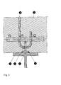
- FIGS. 1 to 4 The various design forms of the profile strips and the associated design options for producing the bond between the steel girder and the concrete slab are explained by way of example in the following FIGS. 1 to 4. Vertical sections through the bonded area are shown here at right angles to the beam span or, in the case of FIGS. 1b and 4b, also in the direction of the beam span.
- Fig. 1 shows a profile bar 2 with a rectangular cross-section, which is welded with its narrow side by 2 fillet welds 4 in the longitudinal direction on the carrier belt 1.
- the profile bar 2 (flat bar) has holes 3 in its cross-section part projecting from the belt at close intervals, as can be seen from FIG. 1b.
- Bars of the lower transverse reinforcement of the reinforced concrete plate 6 are inserted through some of these holes, whereby the load-bearing capacity of the dowel is significantly increased.
- a U-profile with flanges 7 projecting from the belt is welded onto the carrier belt 1 with the aid of the two fillet welds 4.
- Holes 3 are made at close intervals in both flanges 7. This gives a multi-section dowel between the concrete slab and the carrier belt.
- bow-like reinforcement bars 8 are inserted, which are anchored in the steel plate 6.
- short steel bolts 5 can also be inserted through the holes, which fill the entire hole cross section and can be hooked into the stirrup-like reinforcing bars running in the longitudinal direction.
- T-section is shown as a profile bar, which is welded with its flange on both sides by fillet welds 4 on the carrier belt and holes 3 are provided in the projecting web at close intervals.
- T-profiles can be of advantage if the profile is deformed along the weld seams, e.g. can be avoided by punching holes.
- the plate reinforcement is placed on the protruding web of the T-profile from above, so it does not engage in the holes.
- the concrete slab is anchored to the belt by means of the dowel effect of the concrete in the perforated area by simple thin reinforcement bars 8 which are hooked into a part of the holes and perforated bars are used.
- FIG. 4 again shows a profile bar 2 with a rectangular cross-section.
- the large holes 3 which may be round or rectangular, smaller additional holes 9 are arranged. Through these smaller holes rods 5.
- the reinforcement bars of the transverse slab reinforcement are pushed through and held at the height required for the concrete cover.
- the bond is made on the one hand by the concrete dowels in the perforated area, and on the other hand by hook-like reinforcement bars that encompass the transverse reinforcement of the slab.
Abstract
Description
Verbundmittel zur Übertragung von Kräften zwischen Stahlträger und Betonplatte bei Verbundtragwerken, die aus stählernen, in Längsrichtung auf den Gurt des Trägers aufgeschweissten Profilstäben bestehen und in den Beton der Platte eingreifen sind bekannt, z.B. aus der US-A-3736 716.Composite means for transmitting forces between the steel girder and the concrete slab in the case of composite girder structures consisting of steel, longitudinally welded to the girder of the girder and engage in the concrete of the slab are known, e.g. from US-A-3736 716.
Bekannt sind auch Verbundmittel aus Flachstäben mit Rechteck-Querschnitt, die auf einer Seite mit Querrippen in engen Abständen versehen sind und mit der anderen, glatten Seite auf dem Gurt des Stahlträgers aufliegen und mit diesem durch Kehlnähte verbunden sind.Also known are composite materials made of flat bars with a rectangular cross-section, which are provided on one side with transverse ribs at close intervals and rest on the belt of the steel beam with the other, smooth side and are connected to this by fillet welds.
Bekannt ist auch, bei Flachstäben anstelle der Querrippen Löcher in engen Abständen anzuordnen.It is also known to arrange holes at flat intervals instead of the transverse ribs in flat bars.
In beiden Fällen wird durch den aufgeschweissten Flachstab eine Verzahnung in der Kontaktfläche zwischen Betonplatte und Stahlgurt hergestellt, durch die Scherkräfte in Trägerlängsrichtung übertragen werden können. Zur Übertragung von rechtwinklig hierzu verlaufenden, die Platte abhebenden Kräften werden zusätzlich in Richtung der Plattendicke verlaufende Bewehrungsschlaufen oder Kopfbolzendübel benötigt, die auf dem Gurt bzw. dem Flachstab angeschweisst und in der Betonplatte verankert sind.In both cases, the welded flat bar creates a toothing in the contact surface between the concrete slab and the steel belt, through which shear forces can be transmitted in the longitudinal direction of the beam. For the transmission of forces at right angles to this, lifting the slab, additional reinforcement loops or headed dowels running in the direction of the slab thickness are required, which are welded onto the belt or flat bar and anchored in the concrete slab.
Diese Schlaufen oder Bolzen sind beim Transport der Stahlträger oft hinderlich oder setzen - wenn sie erst auf der Baustelle angeschweisst werden - hierfür besondere Massnahmen voraus, die sich preislich ungünstig auswirken.These loops or bolts are often a hindrance when transporting the steel girders or - if they are only welded on at the construction site - require special measures that have an unfavorable price.
Aus diesem Grunde wurde schon vorgeschlagen, Stäbe mit U-Querschnitt zu verwenden, diese mit ihren beiden Flanschenden durch Kehlnähte an den Trägergurt anzuschliessen und den Steg des U-Querschnittes mit Löchern in engen Abständen zu versehen. In diese Löcher können an der Baustelle in den statisch erforderlichen Abständen von oben her bügelartige Bewehrungselemente gesteckt werden, die mit verdickten Enden versehen sind und nach dem Betonieren in dem vom U-Profil umschlossenen Betonkern verankert sind.For this reason, it has already been proposed to use rods with a U-cross section, to connect them with their two flange ends to the support belt by fillet welds, and to provide the web of the U-cross section with holes at close intervals. In these holes, at the construction site, stirrup-like reinforcement elements can be inserted from above at the statically required intervals, which are provided with thickened ends and, after concreting, are anchored in the concrete core enclosed by the U-profile.
In entsprechender Weise können auch Kopfbolzen-Dübel verankert werden.Head bolt dowels can also be anchored in a corresponding manner.
Die Übertragung der Scherkraft erfolgt hier durch Verzahnung, wobei die Betonzähne von oben in die Steglöcher des U-Profils eingreifen. Vorteilhaft ist hier im Vergleich zum gelochten Flachstahlprofil, dass sich auch grössere Zuschlagkörner im Lochbereich mittig vor den U-Steg setzen können, wodurch die Scherfestigkeit in der horizontalen Abscherfläche in Oberkante U-Steg erhöht wird.The transmission of the shear force takes place here by toothing, the concrete teeth engaging in the web holes of the U-profile from above. Compared to the perforated flat steel profile, it is advantageous here that larger aggregate grains can also sit in the center of the hole in front of the U-bar, which increases the shear strength in the horizontal shear surface in the upper edge of the U-bar.
Obwohl bei dieser Lösung die Dübel bzw. Schlaufen ohne Schweissung und auf einfache Weise erst an der Baustelle eingebaut werden können, so setzt sie doch besonders ausgebildete, d.h. mit Verdickungen versehene Bewehrungselemente voraus. Weiter werden die zwischen den Löchern stehengebliebenen Stegteile des U-Profils durch die Verankerung der Dübel bzw. Schlaufen in vertikaler Richtung auf Biegung beansprucht, was örtlich zu grösseren Lochabständen führt. Darüberhinaus muss sichergestellt sein, dass beim Betonieren der Platte der durch das U-Profil umschlossene Hohlraum einwandfrei mit Beton verfüllt ist. Hier wirkt sich nachteilig aus, dass sich im Hohlraum leicht Schmutz oder Wasser ansammeln kann, was die Herstellung einer einwandfreien Betonqualität in diesem hoch beanspruchten Bereich erschwert. (Das gleiche gilt natürlich auch für den Beton im Lochbereich des Flachstabes).Although with this solution the dowels or loops can only be installed at the construction site without welding and in a simple manner, they are still used by specially trained, i.e. reinforcement elements provided with thickening. Furthermore, the web parts of the U-profile that remain between the holes are subjected to bending in the vertical direction by anchoring the dowels or loops, which locally leads to larger hole spacings. In addition, it must be ensured that when concreting the slab, the cavity enclosed by the U-profile is properly filled with concrete. The disadvantage here is that dirt or water can easily accumulate in the cavity, which makes it difficult to produce perfect concrete quality in this highly stressed area. (The same naturally also applies to the concrete in the perforated area of the flat bar).
Berücksichtigt man noch die durch das gelochte U-Profil gegenüber dem gelochten Flachstab bedingten Material-Mehrkosten, so ist durch diese Lösung keine wesentlich ins Gewicht fallende Einsparung zu erzielen.If one also takes into account the additional material costs caused by the perforated U-profile compared to the perforated flat bar, this solution does not result in any significant savings.
Der Erfindung liegt daher die Aufgabe zugrunde, die Verankerung der Betonplatte ohne besondere Schlaufen oder Dübel zu erreichen und die Tragfähigkeit der Profilstäbe als Verbundmittel zu erhöhen und sie damit in wirtschaftlicher und in konstruktiver Hinsicht besser auszunutzen.The invention is therefore based on the object to achieve the anchoring of the concrete slab without special loops or dowels and to increase the load-bearing capacity of the profiled bars as a compound and thus to make better use of them in economic and constructive terms.
Die Lösung besteht darin, dass die vom Trägergurt im allgemeinen rechtwinkelig abstehenden Querschnittsteile der Profilstäbe mit durchgehenden Löchern in engen Abständen versehen sind, deren lichte Weite grösser als der Durchmesser des Grösstkornes des Betons ist und sich durch die Löcher jeweils ein aus dem Beton deu Betonplatte bestehender Betondükel erstrecht. Dies bedeutet, daß durch den Beton im Lochbereich in horizontaler Richtung zweischnittige, dübelartige Verbindungen zwischen Betonplatte und Profilstab ausgebildet sind. Anstelle der bisher waagrechten Scherflächen zwischen Beton und Profilstab bzw. Trägergurt verlaufen die Scherflächen also lotrecht. Damit können bei gleichem Lochquerschnitt und durchgehenden Löchern doppelt so hohe Scherkräfte übertragen werden, da die dübelartigen Verbindungen zwischen Betonplatte und Profilstab zweischnittig ausgenutzt werden können.The solution is that the cross-sectional parts of the profile bars, which generally protrude at right angles from the carrier belt, are provided with through holes at close intervals, the clear width of which is greater than the diameter of the largest grain of the concrete, and through the holes there is an existing concrete plate from the concrete Concrete dowel even more so. This means that two-section, dowel-like connections between the concrete slab and profile bar are formed in the horizontal direction by the concrete in the hole area. Instead of the previously horizontal shear surfaces between the concrete and the profile bar or carrier belt, the shear surfaces run perpendicular. With the same hole cross-section and through holes twice as high shear forces can be transmitted, since the dowel-like connections between the concrete slab and profile bar can be used in two sections.
Durch die im allgemeinen lotrecht stehenden, mit Löchern versehenen Querschnittsteile ist darüberhinaus die Ansammlung von Schmutz oder Wasser im Lochbereich vermieden und die Herstellung eines einwandfreien Betons an dieser Stelle sichergestellt.The generally perpendicular, perforated cross-sectional parts also prevent the accumulation of dirt or water in the perforated area and ensure the production of perfect concrete at this point.
Ein ganz wesentlicher Vorteil der erfindungsgemässen Ausbildung bzw. Anordnung der Profilstäbe besteht jedoch darin, dass über den die Löcher im Profilstab dübelartig durchsetzenden Beton Scherkräfte in beliebiger Richtung übertragen werden können, d.h. also auch rechtwinklig zur Ebene der Gurtfläche so dass damit von vornherein ein Abheben der Betonplatte vom Stahlgurt verhindert wird. _A very significant advantage of the design or arrangement of the profiled bars according to the invention, however, is that shear forces can be transmitted in any direction via the concrete which penetrates through the holes in the profiled bar in a dowel manner, i.e. So also at right angles to the level of the belt surface so that the concrete slab is prevented from lifting from the steel belt from the outset. _
Es sind damit keine Schlaufen oder Dübel zur zugfesten Verbindung zwischen Stahlgurt und Betonplatte erforderlich, sofern die Zugbzw. Scherfestigkeit des Betons im Lochbereich nicht überschritten wird.There are no loops or dowels required for the tensile connection between the steel belt and the concrete slab, provided that the tension or. The shear strength of the concrete in the hole area is not exceeded.
Darüberhinaus besteht die Möglichkeit, die quer zur Trägerspannrichtung verlaufende untere Plattenbewehrung ganz oder teilweise durch die Löcher hindurch zu führen und damit die Wirkung der horizontalen Betondübel wesentlich zu erhöhen.In addition, there is the possibility of the lower one running transversely to the beam clamping direction Lead plate reinforcement completely or partially through the holes and thus significantly increase the effect of the horizontal concrete dowels.
Weiter kann mit Hilfe von dicken stählernen Bolzen, die durch einzelne Löcher hindurch gesteckt sind, die Kraftübertragung zwischen Gurt und Platte im Lochbereich praktisch unbegrenzt vergrössert werden. Damit ergibt sich auch die Möglichkeit, die untere Plattenquerbewehrung von oben auf die Profilstäbe aufzulegen und sich damit der jeweils erforderlichen Betondeckung der Platte ausserhalb des Stahlgurtes anzupassen.Furthermore, with the help of thick steel bolts that are inserted through individual holes, the force transmission between the belt and the plate in the hole area can be increased practically indefinitely. This also makes it possible to place the lower transverse reinforcement on the profile bars from above and thus to adapt to the required concrete cover of the slab outside the steel belt.
Die verschiedenen Ausbildungsformen der Profilleisten und die damit verbundenen konstruktiven Möglichkeiten zur Herstellung des Verbundes zwischen Stahlträger und Betonplatte werden in den folgenden Figuren 1 bis 4 beispielhaft erläutert. Hier sind jeweils Vertikalschnitte durch den Verbundbereich rechtwinklig zur Trägerspannweite bzw. bei Figur 1b und 4b auch in Richtung der Trägerspannweite dargestellt.The various design forms of the profile strips and the associated design options for producing the bond between the steel girder and the concrete slab are explained by way of example in the following FIGS. 1 to 4. Vertical sections through the bonded area are shown here at right angles to the beam span or, in the case of FIGS. 1b and 4b, also in the direction of the beam span.
Fig. 1 zeigt einen Profilstab 2 mit Rechteck-Querschnitt, der mit seiner Schmalseite durch 2 Kehlnähte 4 in Längsrichtung auf den Trägergurt 1 aufgeschweisst ist. Der Profilstab 2 (Flachstab) weist in seinem vom Gurt abstehenden Querschnittsteil Löcher 3 in engen Abständen auf, wie aus Fig.1 b hervorgeht.Fig. 1 shows a
Durch einige dieser Löcher sind Stäbe der unteren Querbewehrung der Stahlbetonplatte 6 hindurchgesteckt, wodurch die Tragfähigkeit des Dübels wesentlich erhöht wird.Bars of the lower transverse reinforcement of the reinforced
In Fig. 2 ist auf den Trägergurt 1 ein U-Profil mit vom Gurt abstehenden Flanschen 7 mit Hilfe der beiden Kehlnähte 4 angeschweisst. In beiden Flanschen 7 sind Löcher 3 in engen Abständen angebracht. Man erhält damit eine vietschnittige Verdübelung zwischen Betonplatte und Trägergurt. Durch einige der einander gegenüberliegende Löcher sind bügelartige Bewehrungsstäbe 8 hindurchgesteckt, die in der Stahlplatte 6 verankert sind. Es können aber auch, wie gestrichelt eingezeichnet ist, kurze Stahlbolzen 5 durch die Löcher hindurch gesteckt werden, die den ganzen Lochquerschnitt ausfüllen und in die in Längsrichtung verlaufende bügelartige Bewehrungsstäbe eingehängt werden können.In Fig. 2, a U-profile with flanges 7 projecting from the belt is welded onto the
In Fig. 3 ist als Profilstab ein T-Querschnitt dargestellt, der mit seinem Flansch beidseitig durch Kehlnähte 4 auf den Trägergurt aufgeschweisst ist und in dessen abstehenden Steg Löcher 3 in engen Abständen vorgesehen sind. T-Profile können von Vorteil sein, wenn Verformungen des Profils längs der Schweissnähte, die z.B. durch das Stanzen von Löchern entstehen können, vermieden werden sollen.In Fig. 3 a T-section is shown as a profile bar, which is welded with its flange on both sides by
Die Plattenbewehrung ist von oben auf den abstehenden Steg des T-Profils aufgelegt, greift also in die Löcher nicht ein. Die Verankerung der Betonplatte mit dem Gurt erfolgt ausser durch die Dübelwirkung des Betons im Lochbereich durch einfache, in einen Teil der Löcher eingehängte beiderseits mit Haken versehene, dünne Bewehrungsstäbe 8. In entsprechender Weise können natürlich auch I-Profile oder T-Profile mit obenliegendem Flansch und jeweils gelochten Stegen verwendet werden.The plate reinforcement is placed on the protruding web of the T-profile from above, so it does not engage in the holes. The concrete slab is anchored to the belt by means of the dowel effect of the concrete in the perforated area by simple
In Fig. 4 ist nochmals ein Profilstab 2 mit Rechteck-Querschnitt dargestellt. Wie im Längsschnitt Fig. 4b zu erkennen sind ausser den grossen Löchern 3 die rund oder auch rechteckig sein können, kleinere Zusatzlöcher 9 angeordnet. Durch diese kleineren Löcher können Stäbe 5. z.B. die Bewehrungsstäbe der Plattenquerbewehrung hindurchgeschoben und in der für die Betondekkung erforderlichen Höhenlage gehaltenwerden. Der Verbund erfolgt auch hier wieder einerseits durch die Betondübel im Lochbereich, andererseits durch hakenartige Bewehrungsstäbe, die die Querbewehrung der Platte umfassen.4 again shows a
Die wirtschaftlichen und konstruktiven Vorteile von Profilstäben als Verbundmittel in den hier dargestellten, erfindungsgemässen Anwendungsbeispielen liegen auf der Hand. Es können durch die zweischnittigen dübelartigen Verbindungen Verbundkräfte in beliebigen, in der Trägerebene liegenden Richtungen übertragen werden. Durch die sowieso vorhandene Querbewehrung der Platte wird die Verdübelungswirkung im Lochbereich der Stege erheblich vergrössert. Zusätzliche Verankerungen der Platte am Gurt sind, wenn überhaupt erforderlich, durch im Betonbau übliche Haken oder Bügel ohne Schweissverbindungen möglich. Das Einbringen des Betons in den Lochbereich bringt keinerlei Probleme Hinzu kommt, dass die erfindungsgemässe Lösung zur Übertragung der Verbundkräfte allen Anforderungen hinsichtlich der Duktilität im Bruchzustand durch Variation der Lochgrössen und Lochabstände gerecht wird.The economic and constructive advantages of profile bars as composite means in the application examples according to the invention shown here are obvious. Due to the two-section dowel-like connections, composite forces can be transmitted in any direction lying in the support plane. Due to the existing transverse reinforcement of the slab, the pegging effect in the hole area of the webs is considerably increased. Additional anchorings of the plate to the belt are possible, if necessary at all, by means of hooks or brackets, which are common in concrete construction, without welding connections. The introduction of the concrete into the hole area does not cause any problems. In addition, the solution according to the invention for transmitting the bond forces satisfies all the requirements regarding ductility in the fractured state by varying the hole sizes and hole spacing.
Claims (2)
Priority Applications (3)
| Application Number | Priority Date | Filing Date | Title |
|---|---|---|---|
| AT85111721T ATE59685T1 (en) | 1985-09-17 | 1985-09-17 | JOINTS FOR REINFORCED CONCRETE COMPOSITE STRUCTURES. |
| EP85111721A EP0215148B1 (en) | 1985-09-17 | 1985-09-17 | Connecting means for a composite concrete supporting construction |
| DE8585111721T DE3581080D1 (en) | 1985-09-17 | 1985-09-17 | COMPOSITES FOR REINFORCED CONCRETE STRUCTURES. |
Applications Claiming Priority (1)
| Application Number | Priority Date | Filing Date | Title |
|---|---|---|---|
| EP85111721A EP0215148B1 (en) | 1985-09-17 | 1985-09-17 | Connecting means for a composite concrete supporting construction |
Publications (2)
| Publication Number | Publication Date |
|---|---|
| EP0215148A1 EP0215148A1 (en) | 1987-03-25 |
| EP0215148B1 true EP0215148B1 (en) | 1991-01-02 |
Family
ID=8193771
Family Applications (1)
| Application Number | Title | Priority Date | Filing Date |
|---|---|---|---|
| EP85111721A Expired - Lifetime EP0215148B1 (en) | 1985-09-17 | 1985-09-17 | Connecting means for a composite concrete supporting construction |
Country Status (3)
| Country | Link |
|---|---|
| EP (1) | EP0215148B1 (en) |
| AT (1) | ATE59685T1 (en) |
| DE (1) | DE3581080D1 (en) |
Cited By (1)
| Publication number | Priority date | Publication date | Assignee | Title |
|---|---|---|---|---|
| WO2008139029A1 (en) * | 2007-05-16 | 2008-11-20 | Rautaruukki Oyj | Composite beam structure |
Families Citing this family (5)
| Publication number | Priority date | Publication date | Assignee | Title |
|---|---|---|---|---|
| DE3909849A1 (en) * | 1988-06-07 | 1989-12-14 | Andrae Hans Peter | REINFORCED CONCRETE CARRIER WITH PANEL CROSS SECTION |
| CA2003060A1 (en) * | 1988-11-16 | 1990-05-16 | Pierre Trouillet | Process for uniting a mass of material to a functional support, and device thus made |
| FR2736667B1 (en) * | 1995-07-13 | 1997-08-14 | Est Centre Tech Equip | DEVICE FOR CONNECTING THE CORE OF A METAL PROFILE TO CONCRETE IN A MIXED CONSTRUCTION |
| DE29615019U1 (en) * | 1996-08-29 | 1996-12-05 | Rojek Richard Prof Dr Ing | Device for the concentrated application of force in concrete |
| BR102018069922A2 (en) * | 2018-09-27 | 2020-04-07 | Prates Aguiar Otavio | spiral steel component by helical reinforcement bar for composition of elements and mixed connections |
Family Cites Families (3)
| Publication number | Priority date | Publication date | Assignee | Title |
|---|---|---|---|---|
| US1922340A (en) * | 1930-09-22 | 1933-08-15 | Leonie S Young | Concrete construction |
| DE821215C (en) * | 1949-12-13 | 1951-11-15 | Bergbau Und Huettenbedarf Ag F | Shear protection for composite beams |
| US3736716A (en) * | 1970-04-11 | 1973-06-05 | Long Span Bridge Consultants I | Means for reducing slippage of steel beam relative to concrete slab |
-
1985
- 1985-09-17 AT AT85111721T patent/ATE59685T1/en active
- 1985-09-17 EP EP85111721A patent/EP0215148B1/en not_active Expired - Lifetime
- 1985-09-17 DE DE8585111721T patent/DE3581080D1/en not_active Expired - Lifetime
Cited By (1)
| Publication number | Priority date | Publication date | Assignee | Title |
|---|---|---|---|---|
| WO2008139029A1 (en) * | 2007-05-16 | 2008-11-20 | Rautaruukki Oyj | Composite beam structure |
Also Published As
| Publication number | Publication date |
|---|---|
| DE3581080D1 (en) | 1991-02-07 |
| EP0215148A1 (en) | 1987-03-25 |
| ATE59685T1 (en) | 1991-01-15 |
Similar Documents
| Publication | Publication Date | Title |
|---|---|---|
| DE3343696C2 (en) | ceiling | |
| EP0040815B1 (en) | Site-assembled composite beam | |
| EP0755473B1 (en) | Dowel strip for bent-up bars | |
| DE2704953A1 (en) | SPATIAL STRUCTURE MADE OF BARS AND PLATES | |
| EP2050887A2 (en) | Lattice girder | |
| EP0023042B1 (en) | Prefabricated floor element for buildings | |
| EP0215148B1 (en) | Connecting means for a composite concrete supporting construction | |
| DE2058714A1 (en) | Ribbed concrete slab | |
| DE2339638C3 (en) | Sheet metal shuttering sheet used as reinforcement for a composite concrete ceiling | |
| EP0811731B1 (en) | Ceiling construction and element | |
| CH651095A5 (en) | REINFORCEMENT ELEMENT FOR TRANSMITTING LATERAL FORCES IN PANEL-LIKE SUPPORT LINKS, e.g. FLAT CEILINGS. | |
| CH665668A5 (en) | HANGER BASKET. | |
| EP0079892B1 (en) | Lattice girder | |
| CH640591A5 (en) | Wooden trussed girder | |
| EP0086966A1 (en) | Reinforced concrete composite beam | |
| EP0034820B1 (en) | Glued truss and formwork constructed therefrom | |
| AT41521B (en) | Reinforced concrete construction with lattice-shaped insert. | |
| DE2141046A1 (en) | REINFORCEMENT ELEMENT FOR PREFABRICATED THIN-SHELLED LARGE-AREA REINFORCED CONCRETE COMPOSITE PANELS | |
| EP0047550B1 (en) | Rectangular shuttering element | |
| DE616739C (en) | T-shaped ceiling beam with a concrete pressure plate and a vertical iron web | |
| DE3700429A1 (en) | STEEL CROSSBAR LATCH FOR CONNECTING SEVERAL SHEET PANEL CARRIERS | |
| DE2251487A1 (en) | SINGLE OR MULTIPLE SPANED BRIDGE STRUCTURE MADE OF PRECAST CONCRETE BEAM | |
| DE2451574C3 (en) | Prestressed concrete deck slab for bridge structures as well as laying equipment and process for their manufacture | |
| DE2612929A1 (en) | Triangular sectioned lattice supported concrete reinforcement - is without lower chords and support diagonals' ends bent inwards | |
| DE2439713A1 (en) | Prefabricated reinforced concrete component for building purposes - is made with reinforcing members without lower tension continuous members |
Legal Events
| Date | Code | Title | Description |
|---|---|---|---|
| PUAI | Public reference made under article 153(3) epc to a published international application that has entered the european phase |
Free format text: ORIGINAL CODE: 0009012 |
|
| AK | Designated contracting states |
Kind code of ref document: A1 Designated state(s): AT BE CH DE FR GB IT LI LU NL SE |
|
| RBV | Designated contracting states (corrected) |
Designated state(s): AT CH DE LI |
|
| 17P | Request for examination filed |
Effective date: 19870908 |
|
| 17Q | First examination report despatched |
Effective date: 19890126 |
|
| GRAA | (expected) grant |
Free format text: ORIGINAL CODE: 0009210 |
|
| AK | Designated contracting states |
Kind code of ref document: B1 Designated state(s): AT CH DE LI |
|
| REF | Corresponds to: |
Ref document number: 59685 Country of ref document: AT Date of ref document: 19910115 Kind code of ref document: T |
|
| REF | Corresponds to: |
Ref document number: 3581080 Country of ref document: DE Date of ref document: 19910207 |
|
| PLBE | No opposition filed within time limit |
Free format text: ORIGINAL CODE: 0009261 |
|
| STAA | Information on the status of an ep patent application or granted ep patent |
Free format text: STATUS: NO OPPOSITION FILED WITHIN TIME LIMIT |
|
| 26N | No opposition filed | ||
| PGFP | Annual fee paid to national office [announced via postgrant information from national office to epo] |
Ref country code: CH Payment date: 19930809 Year of fee payment: 9 |
|
| PGFP | Annual fee paid to national office [announced via postgrant information from national office to epo] |
Ref country code: DE Payment date: 19930924 Year of fee payment: 9 Ref country code: AT Payment date: 19930924 Year of fee payment: 9 |
|
| PG25 | Lapsed in a contracting state [announced via postgrant information from national office to epo] |
Ref country code: AT Effective date: 19940917 |
|
| PG25 | Lapsed in a contracting state [announced via postgrant information from national office to epo] |
Ref country code: LI Effective date: 19940930 Ref country code: CH Effective date: 19940930 |
|
| REG | Reference to a national code |
Ref country code: CH Ref legal event code: PL |
|
| PG25 | Lapsed in a contracting state [announced via postgrant information from national office to epo] |
Ref country code: DE Effective date: 19950601 |