EP0215087B1 - Cross-flow filtration - Google Patents
Cross-flow filtration Download PDFInfo
- Publication number
- EP0215087B1 EP0215087B1 EP86901938A EP86901938A EP0215087B1 EP 0215087 B1 EP0215087 B1 EP 0215087B1 EP 86901938 A EP86901938 A EP 86901938A EP 86901938 A EP86901938 A EP 86901938A EP 0215087 B1 EP0215087 B1 EP 0215087B1
- Authority
- EP
- European Patent Office
- Prior art keywords
- filter
- filter support
- tubes
- support
- tube
- Prior art date
- Legal status (The legal status is an assumption and is not a legal conclusion. Google has not performed a legal analysis and makes no representation as to the accuracy of the status listed.)
- Expired - Lifetime
Links
- 238000009295 crossflow filtration Methods 0.000 title claims description 4
- 238000001914 filtration Methods 0.000 claims abstract description 27
- 239000000463 material Substances 0.000 claims abstract description 22
- 239000010802 sludge Substances 0.000 claims abstract description 14
- 239000012141 concentrate Substances 0.000 claims abstract description 6
- 238000004140 cleaning Methods 0.000 claims description 30
- 239000012530 fluid Substances 0.000 claims description 18
- 238000012360 testing method Methods 0.000 claims description 17
- 238000000034 method Methods 0.000 claims description 12
- 238000001471 micro-filtration Methods 0.000 claims description 12
- 238000001223 reverse osmosis Methods 0.000 claims description 12
- 238000000108 ultra-filtration Methods 0.000 claims description 10
- 239000004753 textile Substances 0.000 claims description 6
- 238000009941 weaving Methods 0.000 claims description 5
- 238000011144 upstream manufacturing Methods 0.000 claims 1
- 238000005273 aeration Methods 0.000 abstract description 4
- 230000015572 biosynthetic process Effects 0.000 abstract 1
- 239000012528 membrane Substances 0.000 description 26
- 239000004744 fabric Substances 0.000 description 23
- XLYOFNOQVPJJNP-UHFFFAOYSA-N water Substances O XLYOFNOQVPJJNP-UHFFFAOYSA-N 0.000 description 17
- 239000002028 Biomass Substances 0.000 description 13
- 239000002245 particle Substances 0.000 description 11
- 239000012466 permeate Substances 0.000 description 11
- 238000010276 construction Methods 0.000 description 8
- 239000007787 solid Substances 0.000 description 8
- 239000000126 substance Substances 0.000 description 7
- XEEYBQQBJWHFJM-UHFFFAOYSA-N Iron Chemical compound [Fe] XEEYBQQBJWHFJM-UHFFFAOYSA-N 0.000 description 6
- OKKJLVBELUTLKV-UHFFFAOYSA-N Methanol Chemical compound OC OKKJLVBELUTLKV-UHFFFAOYSA-N 0.000 description 6
- 238000005452 bending Methods 0.000 description 6
- 238000000576 coating method Methods 0.000 description 6
- 238000011010 flushing procedure Methods 0.000 description 6
- 230000004907 flux Effects 0.000 description 6
- 238000004062 sedimentation Methods 0.000 description 6
- 230000008569 process Effects 0.000 description 5
- VYPSYNLAJGMNEJ-UHFFFAOYSA-N Silicium dioxide Chemical compound O=[Si]=O VYPSYNLAJGMNEJ-UHFFFAOYSA-N 0.000 description 4
- 239000011248 coating agent Substances 0.000 description 4
- 239000011148 porous material Substances 0.000 description 4
- 230000000717 retained effect Effects 0.000 description 4
- 238000000926 separation method Methods 0.000 description 4
- 229910001220 stainless steel Inorganic materials 0.000 description 4
- 239000010935 stainless steel Substances 0.000 description 4
- 239000002351 wastewater Substances 0.000 description 4
- NHNBFGGVMKEFGY-UHFFFAOYSA-N Nitrate Chemical compound [O-][N+]([O-])=O NHNBFGGVMKEFGY-UHFFFAOYSA-N 0.000 description 3
- 239000004411 aluminium Substances 0.000 description 3
- 229910052782 aluminium Inorganic materials 0.000 description 3
- XAGFODPZIPBFFR-UHFFFAOYSA-N aluminium Chemical compound [Al] XAGFODPZIPBFFR-UHFFFAOYSA-N 0.000 description 3
- 239000000440 bentonite Substances 0.000 description 3
- 229910000278 bentonite Inorganic materials 0.000 description 3
- SVPXDRXYRYOSEX-UHFFFAOYSA-N bentoquatam Chemical compound O.O=[Si]=O.O=[Al]O[Al]=O SVPXDRXYRYOSEX-UHFFFAOYSA-N 0.000 description 3
- 239000008280 blood Substances 0.000 description 3
- 210000004369 blood Anatomy 0.000 description 3
- 238000000855 fermentation Methods 0.000 description 3
- 230000004151 fermentation Effects 0.000 description 3
- 239000000835 fiber Substances 0.000 description 3
- 239000011521 glass Substances 0.000 description 3
- 229910052742 iron Inorganic materials 0.000 description 3
- 229920000728 polyester Polymers 0.000 description 3
- -1 polypropylene Polymers 0.000 description 3
- 238000005086 pumping Methods 0.000 description 3
- 239000003643 water by type Substances 0.000 description 3
- IJGRMHOSHXDMSA-UHFFFAOYSA-N Atomic nitrogen Chemical compound N#N IJGRMHOSHXDMSA-UHFFFAOYSA-N 0.000 description 2
- OYPRJOBELJOOCE-UHFFFAOYSA-N Calcium Chemical compound [Ca] OYPRJOBELJOOCE-UHFFFAOYSA-N 0.000 description 2
- OKTJSMMVPCPJKN-UHFFFAOYSA-N Carbon Chemical compound [C] OKTJSMMVPCPJKN-UHFFFAOYSA-N 0.000 description 2
- 239000005909 Kieselgur Substances 0.000 description 2
- 229910002651 NO3 Inorganic materials 0.000 description 2
- 239000004743 Polypropylene Substances 0.000 description 2
- 238000003491 array Methods 0.000 description 2
- 230000008901 benefit Effects 0.000 description 2
- 229910052791 calcium Inorganic materials 0.000 description 2
- 239000011575 calcium Substances 0.000 description 2
- 229910052799 carbon Inorganic materials 0.000 description 2
- 239000000701 coagulant Substances 0.000 description 2
- 238000005345 coagulation Methods 0.000 description 2
- 230000015271 coagulation Effects 0.000 description 2
- 239000000470 constituent Substances 0.000 description 2
- 230000001419 dependent effect Effects 0.000 description 2
- 238000010586 diagram Methods 0.000 description 2
- 239000010840 domestic wastewater Substances 0.000 description 2
- 230000000694 effects Effects 0.000 description 2
- 239000007789 gas Substances 0.000 description 2
- 239000010842 industrial wastewater Substances 0.000 description 2
- 239000007788 liquid Substances 0.000 description 2
- 230000014759 maintenance of location Effects 0.000 description 2
- 238000004519 manufacturing process Methods 0.000 description 2
- 238000005259 measurement Methods 0.000 description 2
- 229910000000 metal hydroxide Inorganic materials 0.000 description 2
- 150000004692 metal hydroxides Chemical class 0.000 description 2
- 239000000203 mixture Substances 0.000 description 2
- 150000002894 organic compounds Chemical class 0.000 description 2
- 239000004033 plastic Substances 0.000 description 2
- 229920003023 plastic Polymers 0.000 description 2
- 239000002985 plastic film Substances 0.000 description 2
- 229920001155 polypropylene Polymers 0.000 description 2
- 229920000915 polyvinyl chloride Polymers 0.000 description 2
- 239000004800 polyvinyl chloride Substances 0.000 description 2
- 239000000047 product Substances 0.000 description 2
- 239000010865 sewage Substances 0.000 description 2
- 238000003860 storage Methods 0.000 description 2
- IVORCBKUUYGUOL-UHFFFAOYSA-N 1-ethynyl-2,4-dimethoxybenzene Chemical compound COC1=CC=C(C#C)C(OC)=C1 IVORCBKUUYGUOL-UHFFFAOYSA-N 0.000 description 1
- VYZAMTAEIAYCRO-UHFFFAOYSA-N Chromium Chemical compound [Cr] VYZAMTAEIAYCRO-UHFFFAOYSA-N 0.000 description 1
- 235000008733 Citrus aurantifolia Nutrition 0.000 description 1
- 229920000742 Cotton Polymers 0.000 description 1
- FYYHWMGAXLPEAU-UHFFFAOYSA-N Magnesium Chemical compound [Mg] FYYHWMGAXLPEAU-UHFFFAOYSA-N 0.000 description 1
- 239000004677 Nylon Substances 0.000 description 1
- 229910019142 PO4 Inorganic materials 0.000 description 1
- 239000004698 Polyethylene Substances 0.000 description 1
- 240000004808 Saccharomyces cerevisiae Species 0.000 description 1
- QAOWNCQODCNURD-UHFFFAOYSA-L Sulfate Chemical compound [O-]S([O-])(=O)=O QAOWNCQODCNURD-UHFFFAOYSA-L 0.000 description 1
- 235000011941 Tilia x europaea Nutrition 0.000 description 1
- 238000009825 accumulation Methods 0.000 description 1
- 239000000654 additive Substances 0.000 description 1
- 230000000996 additive effect Effects 0.000 description 1
- 238000004026 adhesive bonding Methods 0.000 description 1
- 229960005363 aluminium oxide Drugs 0.000 description 1
- 239000010425 asbestos Substances 0.000 description 1
- QVGXLLKOCUKJST-UHFFFAOYSA-N atomic oxygen Chemical compound [O] QVGXLLKOCUKJST-UHFFFAOYSA-N 0.000 description 1
- 235000013361 beverage Nutrition 0.000 description 1
- 230000003851 biochemical process Effects 0.000 description 1
- 230000031018 biological processes and functions Effects 0.000 description 1
- 230000000740 bleeding effect Effects 0.000 description 1
- 230000000903 blocking effect Effects 0.000 description 1
- GBAOBIBJACZTNA-UHFFFAOYSA-L calcium sulfite Chemical compound [Ca+2].[O-]S([O-])=O GBAOBIBJACZTNA-UHFFFAOYSA-L 0.000 description 1
- 235000010261 calcium sulphite Nutrition 0.000 description 1
- 239000004295 calcium sulphite Substances 0.000 description 1
- 239000001913 cellulose Substances 0.000 description 1
- 229920002678 cellulose Polymers 0.000 description 1
- 238000005660 chlorination reaction Methods 0.000 description 1
- 150000001875 compounds Chemical class 0.000 description 1
- 238000001816 cooling Methods 0.000 description 1
- 239000000498 cooling water Substances 0.000 description 1
- 230000008021 deposition Effects 0.000 description 1
- 238000011161 development Methods 0.000 description 1
- 238000000502 dialysis Methods 0.000 description 1
- 238000007599 discharging Methods 0.000 description 1
- 239000003814 drug Substances 0.000 description 1
- 238000004043 dyeing Methods 0.000 description 1
- 238000005516 engineering process Methods 0.000 description 1
- 229960004887 ferric hydroxide Drugs 0.000 description 1
- 235000013305 food Nutrition 0.000 description 1
- 239000003365 glass fiber Substances 0.000 description 1
- 238000010438 heat treatment Methods 0.000 description 1
- XLYOFNOQVPJJNP-UHFFFAOYSA-M hydroxide Chemical compound [OH-] XLYOFNOQVPJJNP-UHFFFAOYSA-M 0.000 description 1
- 230000006872 improvement Effects 0.000 description 1
- 239000003295 industrial effluent Substances 0.000 description 1
- 239000004615 ingredient Substances 0.000 description 1
- 238000009434 installation Methods 0.000 description 1
- IEECXTSVVFWGSE-UHFFFAOYSA-M iron(3+);oxygen(2-);hydroxide Chemical compound [OH-].[O-2].[Fe+3] IEECXTSVVFWGSE-UHFFFAOYSA-M 0.000 description 1
- 238000009940 knitting Methods 0.000 description 1
- 230000002045 lasting effect Effects 0.000 description 1
- 239000004571 lime Substances 0.000 description 1
- 229910052749 magnesium Inorganic materials 0.000 description 1
- 239000011777 magnesium Substances 0.000 description 1
- 229910052751 metal Inorganic materials 0.000 description 1
- 239000002184 metal Substances 0.000 description 1
- 238000005065 mining Methods 0.000 description 1
- 229910052757 nitrogen Inorganic materials 0.000 description 1
- 235000012149 noodles Nutrition 0.000 description 1
- 229920001778 nylon Polymers 0.000 description 1
- 239000005416 organic matter Substances 0.000 description 1
- 239000001301 oxygen Substances 0.000 description 1
- 229910052760 oxygen Inorganic materials 0.000 description 1
- 238000006213 oxygenation reaction Methods 0.000 description 1
- 230000000737 periodic effect Effects 0.000 description 1
- 239000010452 phosphate Substances 0.000 description 1
- 238000002616 plasmapheresis Methods 0.000 description 1
- 229920006255 plastic film Polymers 0.000 description 1
- 238000005498 polishing Methods 0.000 description 1
- 229920000573 polyethylene Polymers 0.000 description 1
- 238000007639 printing Methods 0.000 description 1
- 238000012545 processing Methods 0.000 description 1
- 238000004537 pulping Methods 0.000 description 1
- 238000011084 recovery Methods 0.000 description 1
- 238000004064 recycling Methods 0.000 description 1
- 230000009467 reduction Effects 0.000 description 1
- 238000002407 reforming Methods 0.000 description 1
- 229910052895 riebeckite Inorganic materials 0.000 description 1
- 150000003839 salts Chemical class 0.000 description 1
- 238000009287 sand filtration Methods 0.000 description 1
- 238000012216 screening Methods 0.000 description 1
- 238000006467 substitution reaction Methods 0.000 description 1
- 229910021653 sulphate ion Inorganic materials 0.000 description 1
- 239000000725 suspension Substances 0.000 description 1
- 229920002994 synthetic fiber Polymers 0.000 description 1
- 229920001059 synthetic polymer Polymers 0.000 description 1
- 230000008719 thickening Effects 0.000 description 1
- 238000004065 wastewater treatment Methods 0.000 description 1
Images




Classifications
-
- B—PERFORMING OPERATIONS; TRANSPORTING
- B01—PHYSICAL OR CHEMICAL PROCESSES OR APPARATUS IN GENERAL
- B01D—SEPARATION
- B01D69/00—Semi-permeable membranes for separation processes or apparatus characterised by their form, structure or properties; Manufacturing processes specially adapted therefor
- B01D69/14—Dynamic membranes
-
- B—PERFORMING OPERATIONS; TRANSPORTING
- B01—PHYSICAL OR CHEMICAL PROCESSES OR APPARATUS IN GENERAL
- B01D—SEPARATION
- B01D29/00—Filters with filtering elements stationary during filtration, e.g. pressure or suction filters, not covered by groups B01D24/00 - B01D27/00; Filtering elements therefor
- B01D29/11—Filters with filtering elements stationary during filtration, e.g. pressure or suction filters, not covered by groups B01D24/00 - B01D27/00; Filtering elements therefor with bag, cage, hose, tube, sleeve or like filtering elements
- B01D29/13—Supported filter elements
- B01D29/15—Supported filter elements arranged for inward flow filtration
-
- B—PERFORMING OPERATIONS; TRANSPORTING
- B01—PHYSICAL OR CHEMICAL PROCESSES OR APPARATUS IN GENERAL
- B01D—SEPARATION
- B01D29/00—Filters with filtering elements stationary during filtration, e.g. pressure or suction filters, not covered by groups B01D24/00 - B01D27/00; Filtering elements therefor
- B01D29/50—Filters with filtering elements stationary during filtration, e.g. pressure or suction filters, not covered by groups B01D24/00 - B01D27/00; Filtering elements therefor with multiple filtering elements, characterised by their mutual disposition
- B01D29/52—Filters with filtering elements stationary during filtration, e.g. pressure or suction filters, not covered by groups B01D24/00 - B01D27/00; Filtering elements therefor with multiple filtering elements, characterised by their mutual disposition in parallel connection
- B01D29/54—Filters with filtering elements stationary during filtration, e.g. pressure or suction filters, not covered by groups B01D24/00 - B01D27/00; Filtering elements therefor with multiple filtering elements, characterised by their mutual disposition in parallel connection arranged concentrically or coaxially
-
- B—PERFORMING OPERATIONS; TRANSPORTING
- B01—PHYSICAL OR CHEMICAL PROCESSES OR APPARATUS IN GENERAL
- B01D—SEPARATION
- B01D29/00—Filters with filtering elements stationary during filtration, e.g. pressure or suction filters, not covered by groups B01D24/00 - B01D27/00; Filtering elements therefor
- B01D29/50—Filters with filtering elements stationary during filtration, e.g. pressure or suction filters, not covered by groups B01D24/00 - B01D27/00; Filtering elements therefor with multiple filtering elements, characterised by their mutual disposition
- B01D29/56—Filters with filtering elements stationary during filtration, e.g. pressure or suction filters, not covered by groups B01D24/00 - B01D27/00; Filtering elements therefor with multiple filtering elements, characterised by their mutual disposition in series connection
- B01D29/58—Filters with filtering elements stationary during filtration, e.g. pressure or suction filters, not covered by groups B01D24/00 - B01D27/00; Filtering elements therefor with multiple filtering elements, characterised by their mutual disposition in series connection arranged concentrically or coaxially
-
- B—PERFORMING OPERATIONS; TRANSPORTING
- B01—PHYSICAL OR CHEMICAL PROCESSES OR APPARATUS IN GENERAL
- B01D—SEPARATION
- B01D29/00—Filters with filtering elements stationary during filtration, e.g. pressure or suction filters, not covered by groups B01D24/00 - B01D27/00; Filtering elements therefor
- B01D29/62—Regenerating the filter material in the filter
- B01D29/66—Regenerating the filter material in the filter by flushing, e.g. counter-current air-bumps
-
- B—PERFORMING OPERATIONS; TRANSPORTING
- B01—PHYSICAL OR CHEMICAL PROCESSES OR APPARATUS IN GENERAL
- B01D—SEPARATION
- B01D37/00—Processes of filtration
- B01D37/02—Precoating the filter medium; Addition of filter aids to the liquid being filtered
-
- B—PERFORMING OPERATIONS; TRANSPORTING
- B01—PHYSICAL OR CHEMICAL PROCESSES OR APPARATUS IN GENERAL
- B01D—SEPARATION
- B01D61/00—Processes of separation using semi-permeable membranes, e.g. dialysis, osmosis or ultrafiltration; Apparatus, accessories or auxiliary operations specially adapted therefor
- B01D61/14—Ultrafiltration; Microfiltration
- B01D61/147—Microfiltration
-
- B—PERFORMING OPERATIONS; TRANSPORTING
- B01—PHYSICAL OR CHEMICAL PROCESSES OR APPARATUS IN GENERAL
- B01D—SEPARATION
- B01D63/00—Apparatus in general for separation processes using semi-permeable membranes
- B01D63/06—Tubular membrane modules
- B01D63/068—Tubular membrane modules with flexible membrane tubes
-
- B—PERFORMING OPERATIONS; TRANSPORTING
- B01—PHYSICAL OR CHEMICAL PROCESSES OR APPARATUS IN GENERAL
- B01D—SEPARATION
- B01D63/00—Apparatus in general for separation processes using semi-permeable membranes
- B01D63/10—Spiral-wound membrane modules
- B01D63/107—Specific properties of the central tube or the permeate channel
-
- B—PERFORMING OPERATIONS; TRANSPORTING
- B01—PHYSICAL OR CHEMICAL PROCESSES OR APPARATUS IN GENERAL
- B01D—SEPARATION
- B01D69/00—Semi-permeable membranes for separation processes or apparatus characterised by their form, structure or properties; Manufacturing processes specially adapted therefor
- B01D69/10—Supported membranes; Membrane supports
- B01D69/107—Organic support material
- B01D69/1071—Woven, non-woven or net mesh
-
- B—PERFORMING OPERATIONS; TRANSPORTING
- B01—PHYSICAL OR CHEMICAL PROCESSES OR APPARATUS IN GENERAL
- B01D—SEPARATION
- B01D2201/00—Details relating to filtering apparatus
- B01D2201/04—Supports for the filtering elements
- B01D2201/043—Filter tubes connected to plates
- B01D2201/0438—Filter tubes connected to plates mounted substantially vertically on plates at the lower side of the filter elements
-
- B—PERFORMING OPERATIONS; TRANSPORTING
- B01—PHYSICAL OR CHEMICAL PROCESSES OR APPARATUS IN GENERAL
- B01D—SEPARATION
- B01D2315/00—Details relating to the membrane module operation
- B01D2315/10—Cross-flow filtration
Definitions
- the invention relates to cross-flow filtration.
- EP-A-0 080 777 discloses a device for blood oxygenation or membrane plasmapheresis or dialysis of blood.
- the device is formed by attaching two membranes to each other using spaced, parallel fibres to form an integral array of side-by-side, continuous, separate tubes along which the blood is fed.
- the tubes are of capillary dimensions, having a width of 50-500 micrometres when flat and the fibres having a diameter or height of 10 to 200 micrometres.
- the device works at low pressure, believed to be less than 50 kPa. It is believed that cake build-up would not be expected.
- the present invention provides filter supports as set forth in Claims 1 or 2, a filter as set forth in Claim 13, methods as set forth in Claims 21 or 22 and plant as set forth in Claim 23.
- the invention uses an integral array of side-by-side, continuous, separate tubes into which will be fed fluid to be filtered, and each wall of each tube is highly flexible and is restrained during filtration, when the tubes are under the pressure of the feed, solely by tensile forces in the wall itself.
- the invention provides for microfiltration, ultrafiltration or reverse osmosis, and the seams at which the plies are connected together are strong enough to resist a relative pressure of 400 kPa in the tubes.
- the tubes have an internal diameter of at least 5 mm or 10 mm.
- the invention is used for the particle sizes associated with microfiltration or smaller, i.e. sizes associated with microfiltration, ultrafiltration or reverse osmosis.
- the minimum retained particle sizes for microfiltration and ultrafiltration may be considered to be very roughly 10- 7 to 10- 8 m (colloidal range) and 10- 8 to 10- 9 m (macromolecular range), respectively. Colloidal particles and suspended liquids such as oil could be held back.
- the membrane is often referred to as a pre-coat in microfiltration and as a gel coat in reverse osmosis.
- the cross-flow filter of the invention has a filter support which supports the actual filter material or (dynamic) membrane; the filter membrane may be formed by material circulated across the filter support before the feed is applied or may be formed by the feed itself, either as an inherent ingredient of the feed or as an additive to the feed.
- the filter of the invention also has an inlet for feed which is led to the filter membrane, an outlet for permeate which has passed through the filter membrane, and an outlet for concentrate which is not passed through the filter membrane; the outlet for concentrate will be arranged to ensure back pressure and may have a specific back pressure valve.
- the feed passes under pressure along the surface of the filter membrane and causes turbulence to occur adjacent to the filter membrane.
- the filter support should provide for effective cleaning and the removal of matter which tends to block the interstices or pores of the filter support and gradually reduce the efficacy of the filter. It is found that it is difficult, unless elaborate cleaning methods or systems are used, to dislodge such matter from effectively rigid filter media or from relatively thick filter media such as fire hose carcass material, into which matter penetrates deeply before retention.
- the flexibility of the filter support of the invention is significantly greater than that of a normal fire hose carcase. The flexibility is discussed below under the heading "Flexibility Testing".
- the filter support is collapsible, and there is no mechanical contact with the uninterrupted, effective filtering area of the filter support such as would normally be required in order to support the filter support in a direction at right angles to its face and in a direction opposed to the flow.
- the uninterrupted filter zone can be of substantial area relative to the total area of the filter support.
- the pressure of the feed (more specifically the differential pressure across the filter support and membrane) inflates the filter support, causing it to bulge out, and the filter support collapses at least to some degree when the pressure is relieved.
- the absence of mechanical contact over a large area of the filter support leads to more effective use of the filter support.
- the primary advantage is the ability to provide efficient cleaning of the filter support both mechanically and chemically for the removal of the membrane and filtered material, made possible by the high flexibility, structure and the thinness of the filter support.
- Back-flushing is normally used for cleaning, but even without back-flushing, removing the pressure and thereby causing the filter support partially to collapse can release some trapped material, i.e. a stop and start operation.
- Back-flushing can be done with fluid applied to the external surface of the filter support.
- the fluid may be water, or may be compressed air, particularly when oily or greasy fluids are being filtered.
- Narrow jets of compressed air or high pressure water, applied to the external surface of the filter support, can be used to back-flush while the filter continues to operate, the membrane reforming immediately afterwards - local, momentary collapse of the filter support is effected by reversing the hydraulic gradient.
- the back-flushing however causes no kinking or pleating when filtering re-commences.
- the filter support can be divided in modular form and be robust, and can have a wide application range and a very good temperature and chemical resistance, as well as being relatively cheap.
- the filter support can be made in long lengths e.g. of tens of metres, the preferred minimum length being one metre, thereby reducing the number of end connections per unit area of filter support/membrane, and hence greatly reducing construction costs.
- the filter support need not necessarily be encapsulated in a pressure vessel (except where safety requirements dictate this), and end piping connections can be made directly to e.g. each tube of the filter support. Flexibility aids the production, storage and use of long lengths.
- the invention is used for the particle sizes associated with micro-filtration or smaller, i.e. sizes associated with micro-filtration, ultra-filtration or reverse osmosis.
- the minimum retained particle sizes for micro-filtration and ultra-filtration may be considered to be very roughly 10- 7 to 10- 8 m (colloidal range) and 10- 8 to 10- 9 m (macromolecular range), respectively. Colloidal particles and suspended liquids such as oil could be held back.
- the thickness of the filter support is the distance from face to face of a single wall of the tube, ignoring any random protrusions, and is for many applications preferably not greater than 1 mm.
- a simple measurement can be made by laying the respective wall on a flat platten, placing a thin sheet of glass on top, and measuring the average distance between the glass and the platten.
- the thickness is that of the wall as it would be present in the filter before start-up, i.e. ignoring any layer or membrane deposited on the filter support, either in order to prepare the support for filtration or as a layer of retained material during filtration.
- the tube wall is of a multi-layer type, the tube wall as a whole must still be flexible and preferably has a thickness of not greater than 1 mm.
- the preferred maximum thickness is 0.6 mm to 0.8 mm and in practice thicknesses of 0.24 mm and 0.33 mm have been used.
- the preferred filter support is a flexible textile product or fabric formed from natural, man-made or synthetic fibres, filaments or yarns or a combination thereof in spun or continuous form and of monofilament or multifilament configuration of either a single material or mixtures of e.g. synthetic polymers such as polyester, nylon and polypropylene, natural fibres such as cotton, glass carbon, glass-fibre, carbon fibre and stainless steel.
- synthetic polymers such as polyester, nylon and polypropylene
- natural fibres such as cotton, glass carbon, glass-fibre, carbon fibre and stainless steel.
- the fibres, filaments or yarns will be assembled in the filter support by a weaving, knitting, non-woven or stitch-bonding process to provide a low-cost, highly flexible and self-supporting filter support of suitable pressure rating.
- the integral array of side-by-side tubes can be formed by interlacing at the seams.
- the filter support is woven and the weave is formed of threads extending longitudinally of the tubes and threads extending transversely of the tubes, the interlacing can be achieved if at the seams the transverse threads of one ply pass to the opposite side, the longitudinal and transverse threads preferably being warp and weft threads respectively.
- the preferred construction is a double cloth whereby each wall or layer of the double cloth is a homogeneous and tightly constructed single cloth in its own right.
- the double cloth construction is so arranged such that continuous and isolated tubes are formed as an array of side-by-side tubes in one direction, usually, in the case of woven or knitted filter supports, in the warp direction.
- woven filter supports there is a variety of weaves for making tubes (twill, plain weave, hopsack, card or combination thereof). Twill is a preferred weave providing suitable tightness as well as filtration capability of high flux - suitable tightness avoids pin-hole leaks under pressure.
- the flexibility of the filter support allows ease of cleaning e.g. by back-flushing, and allows assembly into e.g. a spirally configured module without creasing, and assembly into a linearly configured module without major alignment problems;
- the filter support is preferably manufactured in long lengths to minimise the number of manifold connections required, which long lengths can be assembled into modules.
- the filter support is of tight construction and is preferably of a construction that minimises particle entrapment in the filter support itself, i.e. provides ease of cleaning and little pore clogging.
- the preferred filter support construction for applications requiring a membrane layer or precoat, is capable of separating particles such as aluminium or ferric hydroxide flocs, diatomaceous earth, bentonite or other similar filtration aids from water when the filter support is subjected to a pressure in the range 10 to 1000 kPa (although these values are not exclusive).
- the filtration capability is dependent on the filter support and on the characteristics of any layer or membrane deposited on the filter support.
- the layer or membrane can be self-healing if it is damaged or punctured.
- the layer may be formed by constituents of the feed or by laying down a specific layer of for example hydroxide floc.
- Multi-layer coatings can be used, in which a first coating of e.g. kieselguhr, bentonite or cellulose is overlain by a second coating of e.g. a metal hydroxide such as iron, aluminium or zirconium hydroxide.
- a metal hydroxide such as iron, aluminium or zirconium hydroxide.
- coagulants it is preferred in some applications to avoid the addition of coagulants to the feed except during an initial feed to provide a pre-coat layer or membrane. Even for the treatment of water for potable uses, the continuous dosing of coagulants or other water treatment chemicals may not be required, once the pre-coat layer is established.
- the internal diameter of the tubes of the tube array may be for instance from 5 or 10 to 40 mm or up to 200 mm.
- the advantages of a tube are low cost, high burst strength and durability, and tubes enable modules to be provided without difficulty and are also less prone to blocking.
- An array of tubes can provide a single module - for example for 25 mm internal diameter tubes, the array may have 22 to 46 tubes using standard weaving widths of one to two meters in the case of a woven filter support, and be several hundred meters long.
- a hundred meter array of twenty two tubes of 25 mm internal diameter has a filtration area of 170 m 2 .
- Tube life times may be one to three years, depending on the severity of the application.
- the filter support will normally form part of a replaceable module which will consist of the tube array, tube connection headers, piping and valves.
- the individual tubes in the array may be connected in parallel or in series or in parallel/series combination.
- Figures 1 to 3 illustrate that batch concentration, feed and bleed or continuous once-through filtration are possible.
- Figures 1 to 3 show feed, recycle, concentrate and permeate lines 1,2,3 and 4, storage vessels 5, control valves 6, pumps 7, cross-flow microfilters 8 in accordance with the invention, and backpressure valves 9.
- Figure 3 shows a series-taper module configuration such as would be used in continuous operation in a large plant; for instance the number of filters 8 in the individual stages can be 16-8-4-2-1, and one can obtain for example 50% or 60% water recovery per stage. Interstage pumping may be required.
- FIG 4 shows the treatment of primary sewage effluent using an activated sludge process.
- the feed line 1 delivers sewage effluent to a device 10 for screening and grit removal and thence to a primary sedimentation tank 11, a sludge line 12 being shown. From the tank 11, the feed passes to a reactor in the form of an activated sludge aeration vessel 13. Sludge is continuously withdrawn from the vessel 13 by the pump 7, but concentrated sludge is returned along the line 2, rejected concentrate (surplus sludge) being passed along the line 3. Due to the ability of the filter 8 to continue working for long periods, the vessel 13 can be operated with very high sludge concentrations, even up to 15% (dry weight).
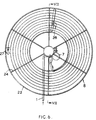
- FIGs 5 to 10 show a spiral arrangement of a filter support 21 in accordance with the invention.
- the filter support 21 is in the form of an integral double cloth array forming a large number of tubes (see Figures 9 and 10).
- the filter support 21 can be as in Example 1 below.
- the filter support 21 is contained within an annular permeate tank 22 and is suspended in position by means of a stainless steel spiral 23 or other suitable support over which the top tube has been slid (or to which it has been fastened), which is in turn hung over, for example, a notched support member 24 by means of stainless steel hooks 25 or another suitable suspending method.
- Suitable weights 26 may be inserted in the bottom tube of the filter support 21, to cause it to hang vertically. The remaining tubes are available for the filter operation.
- Feed and return connections 27 are made at the ends of the tubes, and these connections 27 can be made up in manifolds as desired, the individual connections to the tubes being varied to suit applications.
- Figure 7 indicates one possible arrangement (the only manifolds shown are those in the interior of the spiral).
- the connections 27 will blank off a short length at the end of each filter tube, but it is very small in relation to the uninterrupted area, less than 1 %.
- the pump 7 is connected to the feed line 1. As can be seen, the permeate runs off the outside of the filter support 21 and collects in the bottom of the tank 22.
- Figures 6 to 8 show schematically a cleaning head 28 comprising two legs, which is arranged to pass along a spiral path between the turns of the filter support 21 and projects a fluid from each leg in opposite radial directions onto the filter support 21 to clean and to stabilise the filter support 21 during the cleaning operation; there may be for example suitable nozzles arranged at intervals on the legs.
- the legs of the cleaning head 28 consist of pipes connected by a flexible pipe 29 to a fluid delivery system pipe 30.
- pre-coat On start-up, pre-coat is supplied from a feed tank (not shown) and is recycled until the membrane flux indicates that sufficient pre-coat has been applied. A normal filtration cycle then takes place, lasting a lengthy period.
- the feed When cleaning is required, either at predetermined time intervals or by the lowering of the membrane flux to a minimum value, the feed is either discontinued or supplied at a reduced flow, causing the tubes of the filter support to relax; cleaning water is pumped through the cleaning head 28, flexing the filter support inwards in both directions (front and back), opening the pores and discharging particles from the filter support.
- the cleaning head 28 moves slowly along the spiral path of the filter support 21.
- the flushed water, both external and internal to the tubes, is returned to the supply tank 5 or drained.
- feed flow be supplied to the tubes to prevent accumulation of the deposits in the tubes and possible blockages.
- the cleaning fluid supplied to the cleaning head 28 may alternatively be compressed air or other gas, mixtures of air or other gas and water, and may contain cleaning chemicals.
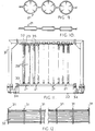
- Figures 11 and 12 show another arrangement for using the same filter support 21 (though in a different configuration).
- several filter supports 21 are arranged in a linear configuration and supported from suitable frames 31.
- Figure 11 shows the detail of the vertical section of a tubular metal support frame 31 and Figure 12 a general plan layout of the support frames 31 and longitudinal support members 32.
- the frames 31 are repeated at suitable intervals determined from structural engineering considerations.
- the filter supports 21 are suspended in position by means of a stainless steel member or other suitable support members 23 over which the top tube has been slid or otherwise fastened, which in turn is attached to a longitudinal support member 32.
- the longitudinal support members 32 are attached to the frames 31 and run continuously in the longitudinal direction for the length of the filter supports 21.
- a rectangular permeate tank 22 is used to collect permeate from the filter support.
- Multiple cleaning heads 28 moving in the longitudinal direction operate similarly to that described in Figures 6 to 8; they are carried on a trolley 33 which tracks on members 34 and upper members 35 slide along the sides of the longitudinal members 32.
- Figure 13 shows a different arrangement of a filter using the multi-tube array 21 described above.
- the tank 44 is profiled so as to follow the surface profile of the array 21, with sufficient space to prevent the array 21 touching the sides of the tank 44.
- a similar arrangement could be used for the connections 27 in the filter of Figures 5 to 10.
- Figures 14 and 15 show a low-cost filter.
- a multi-tube array 21 is supported by guy-ropes 51 secured to stanchions 52.
- Figure 15 shows two arrays 21, one above the other, but there may be a single array or parallel banks of arrays.
- the array(s) 21 are covered in a curtain 53 which hangs down each side and may be a plastic film or sheet such as polyethylene or polypropylene.
- the curtain 53 hangs down into a collection trough 54 in which the permeate is gathered.
- Each run of multi-tube array 21 could be up to say 80 m long - a 10 m run could filter 3 to 4 m 2 hour, enough for the water supply of a small village.
- a handheld nozzle can be used for back flushing.
- Figure 16 shows a cleaning arrangement in which bars 61 (which may be in the form of rollers) are moved along the outer face of each side of the filter support 21.
- the bars 61 have a diameter of 50% to 100% of the diameter of an individual tube of the support 21.
- the bars 61 flex both sides of the filter support inwards and are shown as reducing the diameter of the tube by about 50%, but the reduction could be about 5%, 25%, 75%, 90% or 100% (fully closed), depending on circumstances.
- the bars 61 dislodge material on the filter support 21 and thereby clean the filter support 21.
- the bars 61 should engage all the tubes of the filter support, which can be as in Figures 5-10 or as in Figures 11 and 12, the bars 61 being mounted like (and in place of) the cleaning heads 28.
- An alternative arrangement is to suspend the filter support(s) 21 so that adjacent turns or runs are almost touching, say 1 mm apart, and have a number of turns or runs, say five, of filter support 21 between each pair of bars 21, each turn or run being squeezed.
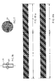
- An array 21 of tubes was woven as a continuous fabric in the double cloth construction, with twenty four tubes being formed by arranging the weave, draft and peg-plan during weaving so as to form continuous tubes in the warp direction of the cloth, separated by cross-over lines formed by the weave interlacing (as shown in Figures 18a and 18b). If wider looms were used, the number and width of tubes could be increased. Ways of forming the tubes other than by using drop-stitches or weft crossing include subsequent stitching, glueing or similar.
- One specific fabric was as follows (the figures in brackets indicate the range of, or alternative, values contemolated. thouah these are not exclusive): Thickness of one wall of tube - 0.33 mm (0.1 - 0.8); Overhanging length in specific flexibility test (see below) done on two slightly different samples (A and B) of Example 1 fabric - 40 and 56 mm (10 - 80 or 100) - in a similar test a 100 mm length drooped by about 80 for both samples.
- Figures 18a and 18b are a conventional weave diagram.
- the strip is taken across the width of the fabric and shows the repeat pattern, which will be repeated a number of times according to the number of tubes.
- the zones x are the seams (or selvedge) and the zones y are the tubes; the zones y will themselves be repeated according to the desired width of the tube, say seven times.
- a black square is where a warp thread is lifted over a weft thread.
- Two cloths or plies are woven, one above the other, but interlacing of both plies occurs at the selvedges and at the seams; the arrangement is such that the weft threads of one ply of one tube then become the weft threads of the other ply of the adjacent tube.
- a strip of not fully-cured polyvinyl chloride solution is applied along the seams (in a process such as "Zimmercoating") on one side or on each side of the fabric after weaving, impregnating the fabric; this strip can be wider than the seam, say 15 mm wide.
- the fabric is heated to about 170°C on a stenter or similar machine to fully cure the polyvinyl chloride.
- the strips become bonded to the woven polyester and form a strong durable seal to the zones or seams where the two plies of the fabric join; this prevents weeping at the seams and reduces the time taken to pre-coat.
- the strips could also be applied to the selvedges.
- the fabric may be heat shrunk or heat set.
- the fabric is of such a kind that when subjected to a pressure of 600 kPa over a period of three years, the cross-sectional area of the tube formed by the fabric does not increase by plastic creep by more than 5%. If excessive extensibility occurs, either on initial pressurisation and/or as the result of plastic creep, there will be unacceptable bleeding through - low extensibility would be less than 10% or preferably 5%.
- the tubes are highly flexible and when they are not pressurised, they collapse such that their cross- section is no longer circular but approximates to a flat polygon with a space of 1 mm between the two longer sides (compare Figures 9 and 10).
- the preferred filter support tube structure incorporating high flexibility, weave tightness to permit the separation of suspended solids and type of weave to facilitate cleaning has in addition to provide a suitable pressure rating to permit long tube lengths (up to 200 m) to be connected in series or parallel.
- the pressures are expressed as relative pressures, i.e. the difference in pressure between the inside and the outside of the tubes. If the burst strength is above a certain value, expressed as the burst pressure, the seams must be strong enough to resist such a value.
- the minimum tube burst pressure is 400 kPa.
- Preferred tube burst pressures are above 1000 kPa and up to 8000 kPa, depending on the filter support. In the case of woven filter supports, the weave pattern and types of fibres, filaments or yarns are chosen to minimise opening of the pores of the filter support during operation under pressure.
- the frictional pressure drop may be high and interstage pumping may be a requirement for high velocity applications.
- the pressure rating should be such as to permit long tube lengths (up to 200 m) to be connected in series.
- Practical velocities are usually in the range 1-3 or 5 m/s, a pressure drop of 65-2500 kPa being expected for a hundred meter tube length of internal diameter 25 mm.
- the inherent water flux is usually in excess of 1500 litres/m 2 h at 150 kPa, but this is usually reduced by the addition of the pre-coat, to an extent dependent on the chemicals or substances used.
- Table 1 provides information on module sizes for 25 mm internal diameter tubes as above, considering a 22 tube module.
- the filter of Figures 5 to 10 was used, the modules being mounted in a tank whose dimensions (diameter x height) are given in Table 1.
- a batch concentration mode of operation is used, on the minimum exit velocity basis.
- the filter was as in Figures 5 to 7, the tank being 1.2 m high, the arrangement was as in Figure 1, and the filter support was as in Example 1. Details are:
- a small pilot unit was set up at a factory to treat factory effluent for the removal of organic matter and suspended solids.
- the effluent was dosed with 25 mg/I Fe as ferric sulphate.
- the operating conditions were:
- the permeate flux was 250 to 320 I/m 2 h under this range of operating conditions for a batch concentration of the feed to the filter of 7600 to 21500 mg/I suspended solids measured at the reject end of the filter.
- the permeate (product) contained less than 0.3 mg/I of suspended solids.
- a rectangular strip of a single wall of the tubular filter support is cut so that the axis of the tube is parallel to the long side of the rectangle; if the seams are coated, the strip should be cut so as to include no coating.
- a strip will only give the "axial" bending length or overhang for a tube, estimates can be made of the flexibility in the direction at 90°, giving a transverse bending length or overhang.
- the "axial" and “transverse” flexural rigidities are roughly similar and it is preferred that one is not more than ten or five, but preferably three, times the other; more generally it is preferred that the flexural rigidity is roughly the same in all directions, the flexural rigidity in any direction preferably not being more than ten or five or three times that in any other direction.
- the diameter of the tube was too small to give proper test strips for transverse measurements, and estimates were made using strips cut across the array of tubes, comparing the bending with that of complete tubes in the axial direction - in each case, the tube was flattened with the opposing walls in contact. Table 4 expresses such results. No transverse result could be obtained for the fire hose, but it was believed that the transverse flexural rigidity was much greater than the axial flexural rigidity.
- test results expressed herein do not eliminate the effect of the weight of the material. When concerned with a narrow range of weights, as in the preferred embodiments of the present invention, this is not of great significance.
- BS 3356:1961 explains how to obtain a weight-corrected value, namely the flexural rigidity.
- An equivalent SFT weight corrected value or SFT rigidity can be obtained by the formula 0.1 W 1 L 3 where W 1 is the weight in g/m 2 and L is the overhanging length in cms.
- the original testing was carried out on a double-ply fabric of weight 434 g/m 2 (single-wall weight 217 g/m 2 ); the actual overhanging length was 40 mm but the preferred maximum was 80 or 100 mm; these lengths give preferred maximum BS bending lengths of about 38 or 48 mm (say 40 or 50 mm), maximum SFT rigidities of 11110.4 or 21700 mg.cm (say 11100 or 22000 (mg.cm)) and maximum BS flexural rigidities of 1191 or 2400 mg.cm (say 1200 or 2400 or preferably 2500 mg.cm).
- Tables 2 to 4 below set out mean test results for four suitable samples and for a relatively flexible fire hose carcase.
- Samples A and B are as for Example 1 and Samples C and D were made as in Example 1 but woven with 22 tubes (and Sample C is of slightly differing weave). The strips cut were 200 x 25 mm.
Landscapes
- Chemical Kinetics & Catalysis (AREA)
- Chemical & Material Sciences (AREA)
- Engineering & Computer Science (AREA)
- Water Supply & Treatment (AREA)
- Separation Using Semi-Permeable Membranes (AREA)
- Filtration Of Liquid (AREA)
- Lubrication Details And Ventilation Of Internal Combustion Engines (AREA)
- Filtering Materials (AREA)
- Nitrogen Condensed Heterocyclic Rings (AREA)
- Pharmaceuticals Containing Other Organic And Inorganic Compounds (AREA)
- Separation By Low-Temperature Treatments (AREA)
- Treatment Of Sludge (AREA)
- Water Treatment By Sorption (AREA)
- Electrostatic Charge, Transfer And Separation In Electrography (AREA)
- Current-Collector Devices For Electrically Propelled Vehicles (AREA)
- Glass Compositions (AREA)
- Electrical Discharge Machining, Electrochemical Machining, And Combined Machining (AREA)
- Filtering Of Dispersed Particles In Gases (AREA)
- Apparatus For Radiation Diagnosis (AREA)
- Escalators And Moving Walkways (AREA)
- Solid-Sorbent Or Filter-Aiding Compositions (AREA)
Priority Applications (1)
| Application Number | Priority Date | Filing Date | Title |
|---|---|---|---|
| AT86901938T ATE70985T1 (de) | 1985-03-12 | 1986-03-12 | Querstromfiltration. |
Applications Claiming Priority (4)
| Application Number | Priority Date | Filing Date | Title |
|---|---|---|---|
| GB858506350A GB8506350D0 (en) | 1985-03-12 | 1985-03-12 | Cross-flow filtration |
| GB8506350 | 1985-03-12 | ||
| GB8520736 | 1985-08-19 | ||
| GB8520736 | 1985-08-19 |
Publications (2)
| Publication Number | Publication Date |
|---|---|
| EP0215087A1 EP0215087A1 (en) | 1987-03-25 |
| EP0215087B1 true EP0215087B1 (en) | 1992-01-02 |
Family
ID=26288966
Family Applications (1)
| Application Number | Title | Priority Date | Filing Date |
|---|---|---|---|
| EP86901938A Expired - Lifetime EP0215087B1 (en) | 1985-03-12 | 1986-03-12 | Cross-flow filtration |
Country Status (23)
| Country | Link |
|---|---|
| US (1) | US4765906A (da) |
| EP (1) | EP0215087B1 (da) |
| JP (1) | JP2553060B2 (da) |
| KR (1) | KR930005286B1 (da) |
| CN (1) | CN1025290C (da) |
| AT (1) | ATE70985T1 (da) |
| AU (1) | AU585327B2 (da) |
| BR (1) | BR8605828A (da) |
| CA (1) | CA1279271C (da) |
| DE (1) | DE3683223D1 (da) |
| DK (1) | DK169059B1 (da) |
| ES (1) | ES296743Y (da) |
| FI (1) | FI85109C (da) |
| GB (1) | GB2191107B (da) |
| IE (1) | IE58559B1 (da) |
| IL (1) | IL78134A (da) |
| MX (1) | MX169131B (da) |
| NO (1) | NO173769C (da) |
| NZ (1) | NZ215451A (da) |
| OA (1) | OA08549A (da) |
| PH (1) | PH24558A (da) |
| PT (1) | PT82184B (da) |
| WO (1) | WO1986005413A1 (da) |
Families Citing this family (41)
| Publication number | Priority date | Publication date | Assignee | Title |
|---|---|---|---|---|
| SE451429B (sv) * | 1986-01-20 | 1987-10-12 | Asea Atom Ab | Sett att regenerera en separationsanordning for ett vetskeformigt medium innehallande olosta bestandsdelar |
| ZA87553B (en) * | 1986-01-31 | 1988-03-30 | Water Res Commission | Dewatering slurries |
| JPH02245205A (ja) * | 1989-03-20 | 1990-10-01 | Ngk Insulators Ltd | 機械油の回収方法 |
| GB2253360B (en) * | 1989-10-05 | 1993-06-02 | Crossflow Microfiltration Ltd | Causing liquid/solid interaction |
| GB8922503D0 (en) * | 1989-10-05 | 1989-11-22 | Crossflow Microfiltration Ltd | Causing phases to interact |
| US5116502A (en) * | 1990-09-27 | 1992-05-26 | Ferguson George E | Elongate housing with end cap members |
| US5374356A (en) * | 1992-07-28 | 1994-12-20 | Pall Corporation | Fluid treatment process using dynamic microfiltration and ultrafiltration |
| GB9223552D0 (en) * | 1992-11-10 | 1992-12-23 | Vickers Shipbuilding & Eng | Improvements in or relating to the treatment of effluents |
| JPH0648820U (ja) * | 1992-12-07 | 1994-07-05 | 水道機工株式会社 | 透過膜によるろ過装置 |
| WO1994015703A1 (en) * | 1993-01-14 | 1994-07-21 | Scimat Limited | A filter |
| US5891333A (en) | 1996-09-24 | 1999-04-06 | Ferguson; George E. | Modular multi-stage water filter apparatus |
| US6428705B1 (en) | 1996-11-26 | 2002-08-06 | Microbar Incorporated | Process and apparatus for high flow and low pressure impurity removal |
| NL1013263C2 (nl) * | 1999-10-11 | 2001-04-17 | Kiwa Nv | Werkwijze voor het zuiveren van water door membraanfiltratie. |
| NL1016705C2 (nl) * | 2000-11-24 | 2002-05-27 | Paques Water Systems B V | Inrichting en werkwijze voor het reinigen van een flu´dum, zoals water. |
| DK200100286U4 (da) * | 2001-10-24 | 2003-02-14 | Bin X As | Filtreringssystem med hydrofile kapillar-membraner |
| JP2003225506A (ja) * | 2002-02-05 | 2003-08-12 | Daicen Membrane Systems Ltd | 汚染排水の処理方法 |
| DE10236664B4 (de) * | 2002-08-09 | 2016-05-12 | Sartorius Stedim Biotech Gmbh | Verfahren und Vorrichtung zur adsorptiven Stofftrennung |
| NL1028247C2 (nl) * | 2005-02-10 | 2006-08-11 | Fluxxion B V | Inrichting en werkwijze voor het filtreren van vloeistof. |
| DE102005039385A1 (de) * | 2005-08-20 | 2007-02-22 | Premark Feg L.L.C., Wilmington | Transport-Geschirrspülmaschine |
| US7384549B2 (en) | 2005-12-29 | 2008-06-10 | Spf Innovations, Llc | Method and apparatus for the filtration of biological solutions |
| DE102007040892A1 (de) | 2007-08-24 | 2009-02-26 | Fsp Fluid Systems Partners Holding Ag | Gewelltes oder gefaltetes Flachmaterial |
| EP2361233A4 (en) * | 2008-09-26 | 2013-01-09 | Imerys Filtration Minerals Inc | DIATOME ENERGY PRODUCTS WITH REDUCED RESISTANCE TO SOLUBLE METALS, METHOD FOR REDUCING THE CONTENT OF SOLUBLE METALS IN DIATOMEEN DERIVATIVES AND METHOD FOR THEIR USE |
| US8454829B2 (en) * | 2008-09-29 | 2013-06-04 | Scott P. Yaeger | Spiral crossflow filter |
| US9452390B2 (en) | 2008-09-29 | 2016-09-27 | Scott P. Yaeger | Spiral crossflow filter |
| CN102892576B (zh) | 2010-04-20 | 2016-02-10 | 法伊布拉卡斯特有限公司 | 成形的板膜元件和过滤系统 |
| CN102059015B (zh) * | 2010-11-22 | 2012-09-05 | 宋健 | 一种层式过滤组件 |
| KR102015613B1 (ko) | 2011-10-20 | 2019-08-28 | 파이브라케스트 리미티드 | 성형 시이트 막 요소를 코팅하기 위한 코팅 기기 및 공정 |
| EP2990087B1 (en) * | 2013-04-23 | 2017-06-28 | Toyota Jidosha Kabushiki Kaisha | Oil degradation suppressor |
| JP2015129095A (ja) | 2013-12-19 | 2015-07-16 | ロレアル | 組成物 |
| US10369524B2 (en) * | 2014-01-06 | 2019-08-06 | W. L. Gore & Associates, Inc. | Autogenous cleaning filtration method and device |
| US10207225B2 (en) | 2014-06-16 | 2019-02-19 | Emd Millipore Corporation | Single-pass filtration systems and processes |
| WO2015195453A2 (en) | 2014-06-16 | 2015-12-23 | Emd Millipore Corporation | Methods for increasing the capacity of flow-through processes |
| ES2742704T3 (es) | 2014-06-25 | 2020-02-17 | Emd Millipore Corp | Elementos, módulos y sistemas de filtro compactos, enrollados en espiral |
| SG11201508664VA (en) | 2014-08-29 | 2016-03-30 | Emd Millipore Corp | Single Pass Tangential Flow Filtration Systems and Tangential Flow Filtration Systems withRecirculation of Retentate |
| CN108325391B (zh) | 2014-08-29 | 2021-05-18 | Emd 密理博公司 | 过滤液体进料的方法 |
| CA3023486C (en) | 2016-06-09 | 2022-03-29 | Emd Millipore Corporation | Radial-path filter elements, systems and methods of using same |
| EP3146958A1 (en) * | 2016-09-23 | 2017-03-29 | Welspun India Limited | Pillow article, textile material, and related methods |
| CN108479398B (zh) * | 2018-05-29 | 2020-09-25 | 浙江章华保健美发实业有限公司 | 一种高拉伸性能的过滤结构 |
| US10864483B2 (en) | 2018-11-16 | 2020-12-15 | Integrated Protein Technologies, Snc. | Molecular weight filtration system and apparatus |
| FR3101870B1 (fr) * | 2019-10-10 | 2021-10-01 | Dfm Depannages Fournitures Maintenance | Systeme de traitement et de recyclage des eaux grises, procede de traitement et de recyclage des eaux grises, procede de commande d’un systeme |
| JP7140217B2 (ja) * | 2021-02-26 | 2022-09-21 | 栗田工業株式会社 | Roシステムの制御方法 |
Family Cites Families (35)
| Publication number | Priority date | Publication date | Assignee | Title |
|---|---|---|---|---|
| US2600458A (en) * | 1950-03-25 | 1952-06-17 | Harry A Ackley | Upflow pressure diatomite filtering apparatus |
| US2861649A (en) * | 1955-05-03 | 1958-11-25 | Junkmann Heinzjosef | Filter hose cleaners |
| NL288186A (nl) * | 1963-01-25 | 1965-03-10 | P De Gruyter En Zoon N V | Werkwijze voor het selectief ontwateren van waterige vloeibare systemen |
| FR1422314A (fr) * | 1964-11-12 | 1965-12-24 | élément à toile filtrante | |
| ES332639A1 (es) * | 1965-10-23 | 1970-02-01 | Us Atomic Energy Commision | Metodo para hacer una membrana permeable, dinamica. |
| US3383840A (en) * | 1966-05-10 | 1968-05-21 | Cottrell Res Inc | Dust collecting system |
| US3503789A (en) * | 1967-05-05 | 1970-03-31 | Atomic Energy Commission | Method of making a dynamic solute-rejecting membrane |
| US3431201A (en) * | 1967-08-29 | 1969-03-04 | Atomic Energy Commission | Hyperfiltration process having ion exchange pretreatment |
| US3592763A (en) * | 1968-02-21 | 1971-07-13 | Hydronautics | Dynamically formed,reverse osmosis membranes |
| US3577339A (en) * | 1968-04-02 | 1971-05-04 | Atomic Energy Commission | Filtration method of separating liquids from extraneous materials |
| GB1255268A (en) * | 1968-04-02 | 1971-12-01 | Atomic Energy Commission | Filtration method of separating liquids from extraneous materials |
| US3521753A (en) * | 1968-04-30 | 1970-07-28 | Werner P Schoening | Filtering and heating of liquids by use of a flexible cellular blanket |
| US3563889A (en) * | 1969-01-03 | 1971-02-16 | Abcor Inc | Integral semipermeable membrane and braided support tube |
| GB1253117A (da) * | 1969-09-26 | 1971-11-10 | ||
| US3589516A (en) * | 1970-07-06 | 1971-06-29 | Us Agriculture | Uniflow filter with gasifying means |
| US3785498A (en) * | 1971-01-19 | 1974-01-15 | J Fernandez | Helical coil filter apparatus |
| US3778366A (en) * | 1971-05-28 | 1973-12-11 | Atomic Energy Commission | Process for treatment of aqueous suspensions |
| US3738813A (en) * | 1971-06-04 | 1973-06-12 | W Esmond | Mass transfer device and method of making same |
| US3733265A (en) * | 1971-11-22 | 1973-05-15 | Atomic Energy Commission | Cross-flow filtration process for removal of total organic carbon and phosphates from aqueous sewage effluents |
| US3784470A (en) * | 1972-11-20 | 1974-01-08 | Philco Ford Corp | Composite coiled membrane assembly |
| US4039457A (en) * | 1973-02-02 | 1977-08-02 | Robert Bosch G.M.B.H. | Coiled filter element for filtering of liquids |
| US3835040A (en) * | 1973-04-04 | 1974-09-10 | Atomic Energy Commission | Cross-flow filtration process |
| US3976569A (en) * | 1975-02-25 | 1976-08-24 | The United States Of America As Represented By The United States Energy Research And Development Administration | Water softening process |
| DE2511195C3 (de) * | 1975-03-14 | 1978-08-17 | Basf Ag, 6700 Ludwigshafen | Verfahren zum Filtrieren und Filter zur Durchführung des Verfahrens |
| US4022692A (en) * | 1975-08-01 | 1977-05-10 | Erika, Inc. | Non-woven support screen for mass transfer devices |
| DE2539743A1 (de) * | 1975-09-06 | 1977-03-10 | Draegerwerk Ag | Bewegliches filtergeraet zur asepsis von patienten |
| DE2541383C3 (de) * | 1975-09-17 | 1978-05-24 | Haver & Boecker, 4740 Oelde | Verfahren zum Herstellen von mehrlagigen Filterhohlkörpern für gasförmige oder flüssige Medien und danach hergestellter Filterhohlkörper |
| US4035305A (en) * | 1975-10-08 | 1977-07-12 | Baxter Laboratories, Inc. | Support member construction for semipermeable membrane |
| GB1566264A (en) * | 1976-04-23 | 1980-04-30 | Whatman Reeve Angel Ltd | Inside-to-outside flow filter tube and method of manufacturing same |
| US4169754A (en) * | 1977-06-03 | 1979-10-02 | Whatman Reeve Angel Limited | Filter tube and method of preparing same |
| DE2929655A1 (de) * | 1979-07-21 | 1981-02-12 | Sartorius Gmbh | Vorrichtung zur massenuebertragung zwischen fluiden |
| US4247394A (en) * | 1979-08-02 | 1981-01-27 | Industrial Filter & Pump Mfg. Co. | Filter element and method of use |
| EP0079040A3 (en) * | 1981-11-06 | 1984-12-27 | Hydronautics, Incorporated | Method and apparatus for increasing the cross-flow filtration fluxes of liquids containing suspended solids |
| US4390575A (en) * | 1981-12-02 | 1983-06-28 | Baxter Travenol Laboratories, Inc. | Multichanneled diffusion device |
| US4476022A (en) * | 1983-03-11 | 1984-10-09 | Doll David W | Spirally wrapped reverse osmosis membrane cell |
-
1986
- 1986-03-11 US US06/838,515 patent/US4765906A/en not_active Expired - Lifetime
- 1986-03-12 ES ES1986296743U patent/ES296743Y/es not_active Expired
- 1986-03-12 KR KR1019860700794A patent/KR930005286B1/ko not_active Expired - Lifetime
- 1986-03-12 IE IE65586A patent/IE58559B1/en not_active IP Right Cessation
- 1986-03-12 PT PT82184A patent/PT82184B/pt not_active IP Right Cessation
- 1986-03-12 AT AT86901938T patent/ATE70985T1/de not_active IP Right Cessation
- 1986-03-12 EP EP86901938A patent/EP0215087B1/en not_active Expired - Lifetime
- 1986-03-12 MX MX001844A patent/MX169131B/es unknown
- 1986-03-12 BR BR8605828A patent/BR8605828A/pt not_active IP Right Cessation
- 1986-03-12 CN CN86102465A patent/CN1025290C/zh not_active Expired - Lifetime
- 1986-03-12 DE DE8686901938T patent/DE3683223D1/de not_active Expired - Lifetime
- 1986-03-12 GB GB8627049A patent/GB2191107B/en not_active Expired
- 1986-03-12 CA CA000503944A patent/CA1279271C/en not_active Expired - Lifetime
- 1986-03-12 AU AU55462/86A patent/AU585327B2/en not_active Expired
- 1986-03-12 NZ NZ215451A patent/NZ215451A/en unknown
- 1986-03-12 PH PH33517A patent/PH24558A/en unknown
- 1986-03-12 JP JP61501874A patent/JP2553060B2/ja not_active Expired - Lifetime
- 1986-03-12 WO PCT/GB1986/000143 patent/WO1986005413A1/en not_active Ceased
- 1986-03-13 IL IL78134A patent/IL78134A/xx unknown
- 1986-11-11 NO NO864500A patent/NO173769C/no unknown
- 1986-11-11 FI FI864590A patent/FI85109C/fi not_active IP Right Cessation
- 1986-11-12 OA OA58992A patent/OA08549A/xx unknown
- 1986-11-12 DK DK541786A patent/DK169059B1/da not_active IP Right Cessation
Also Published As
Similar Documents
| Publication | Publication Date | Title |
|---|---|---|
| EP0215087B1 (en) | Cross-flow filtration | |
| EP1210298B1 (en) | System for operation of multiple membrane filtration assemblies | |
| US7410584B2 (en) | Methods and apparatus for treating wastewater employing a high rate clarifier and a membrane | |
| Aptel et al. | Categories of membrane operations | |
| Zirehpour et al. | Membranes for wastewater treatment | |
| Engelhardt et al. | Integration of membrane filtration into the activated sludge process in municipal wastewater treatment | |
| KR20040111343A (ko) | 막 분리 장치 및 막 분리 방법 | |
| KR100241198B1 (ko) | 가변 필터층을 갖는 여과장치 | |
| JPH09141063A (ja) | 中空糸膜モジュール | |
| CA3102361A1 (en) | Method and apparatus for treating commercial and industrial laundry wastewater | |
| US20070151916A1 (en) | Network for supporting spiral wound membrane cartridges for submerged operation | |
| CA3018721A1 (en) | Bioreactor assembly | |
| US4200533A (en) | Hyperfiltration apparatus and method of fluid treatment | |
| JP2000325757A (ja) | 懸濁液濃縮装置 | |
| JP3500218B2 (ja) | 膜モジュール | |
| JP2000300964A (ja) | 中空糸膜モジュール | |
| JP2910459B2 (ja) | 固液分離システム | |
| JP3486308B2 (ja) | 膜処理装置 | |
| Vigneswaran | Reverse Osmosis | |
| JPH0747238A (ja) | 中空糸膜モジュール及びその支持方法 | |
| KR20100094643A (ko) | 여과 시스템 | |
| WO2002004089A1 (en) | Filtration apparatus and process with collapsible filer tubes | |
| JPH01254288A (ja) | 平膜式の限外濾過膜を用いた廃液処理方法 | |
| ZA200907042B (en) | Reserve flow microfiltration |
Legal Events
| Date | Code | Title | Description |
|---|---|---|---|
| PUAI | Public reference made under article 153(3) epc to a published international application that has entered the european phase |
Free format text: ORIGINAL CODE: 0009012 |
|
| AK | Designated contracting states |
Kind code of ref document: A1 Designated state(s): AT BE CH DE FR GB IT LI LU NL SE |
|
| 17P | Request for examination filed |
Effective date: 19870323 |
|
| 17Q | First examination report despatched |
Effective date: 19880614 |
|
| RBV | Designated contracting states (corrected) |
Designated state(s): AT BE CH DE FR IT LI LU NL SE |
|
| GRAA | (expected) grant |
Free format text: ORIGINAL CODE: 0009210 |
|
| AK | Designated contracting states |
Kind code of ref document: B1 Designated state(s): AT BE CH DE FR IT LI LU NL SE |
|
| REF | Corresponds to: |
Ref document number: 70985 Country of ref document: AT Date of ref document: 19920115 Kind code of ref document: T |
|
| ITF | It: translation for a ep patent filed | ||
| REF | Corresponds to: |
Ref document number: 3683223 Country of ref document: DE Date of ref document: 19920213 |
|
| ET | Fr: translation filed | ||
| PLBE | No opposition filed within time limit |
Free format text: ORIGINAL CODE: 0009261 |
|
| STAA | Information on the status of an ep patent application or granted ep patent |
Free format text: STATUS: NO OPPOSITION FILED WITHIN TIME LIMIT |
|
| 26N | No opposition filed | ||
| EPTA | Lu: last paid annual fee | ||
| EAL | Se: european patent in force in sweden |
Ref document number: 86901938.0 |
|
| REG | Reference to a national code |
Ref country code: CH Ref legal event code: PFA Free format text: EPOC LIMITED TRANSFER- BBV-EPOC LIMITED |
|
| NLT1 | Nl: modifications of names registered in virtue of documents presented to the patent office pursuant to art. 16 a, paragraph 1 |
Owner name: BBV-EPOC LIMITED |
|
| REG | Reference to a national code |
Ref country code: CH Ref legal event code: PFA Free format text: BBV-EPOC LIMITED,6 ESTERBROOKE STREET HYDE PLACE,WESTMINSTER/LONDON (GB) TRANSFER- BBV-EPOC LIMITED,GROSVENOR HOUSE 69 LONDON ROAD REDHILL,SURREY RH1 1LQ (GB) |
|
| REG | Reference to a national code |
Ref country code: FR Ref legal event code: CD |
|
| REG | Reference to a national code |
Ref country code: FR Ref legal event code: CA |
|
| PGFP | Annual fee paid to national office [announced via postgrant information from national office to epo] |
Ref country code: NL Payment date: 20050303 Year of fee payment: 20 |
|
| PGFP | Annual fee paid to national office [announced via postgrant information from national office to epo] |
Ref country code: SE Payment date: 20050304 Year of fee payment: 20 |
|
| PGFP | Annual fee paid to national office [announced via postgrant information from national office to epo] |
Ref country code: FR Payment date: 20050308 Year of fee payment: 20 |
|
| PGFP | Annual fee paid to national office [announced via postgrant information from national office to epo] |
Ref country code: DE Payment date: 20050310 Year of fee payment: 20 |
|
| PGFP | Annual fee paid to national office [announced via postgrant information from national office to epo] |
Ref country code: AT Payment date: 20050311 Year of fee payment: 20 |
|
| PGFP | Annual fee paid to national office [announced via postgrant information from national office to epo] |
Ref country code: CH Payment date: 20050316 Year of fee payment: 20 Ref country code: LU Payment date: 20050316 Year of fee payment: 20 |
|
| PGFP | Annual fee paid to national office [announced via postgrant information from national office to epo] |
Ref country code: IT Payment date: 20050330 Year of fee payment: 20 |
|
| PGFP | Annual fee paid to national office [announced via postgrant information from national office to epo] |
Ref country code: BE Payment date: 20050509 Year of fee payment: 20 |
|
| PG25 | Lapsed in a contracting state [announced via postgrant information from national office to epo] |
Ref country code: NL Free format text: LAPSE BECAUSE OF EXPIRATION OF PROTECTION Effective date: 20060312 |
|
| REG | Reference to a national code |
Ref country code: CH Ref legal event code: PL |
|
| NLV7 | Nl: ceased due to reaching the maximum lifetime of a patent |
Effective date: 20060312 |
|
| EUG | Se: european patent has lapsed | ||
| BE20 | Be: patent expired |
Owner name: *BBV-EPOC LTD Effective date: 20060312 |