EP0214846B1 - Sample monitoring instrument for on-line application - Google Patents
Sample monitoring instrument for on-line application Download PDFInfo
- Publication number
- EP0214846B1 EP0214846B1 EP86306855A EP86306855A EP0214846B1 EP 0214846 B1 EP0214846 B1 EP 0214846B1 EP 86306855 A EP86306855 A EP 86306855A EP 86306855 A EP86306855 A EP 86306855A EP 0214846 B1 EP0214846 B1 EP 0214846B1
- Authority
- EP
- European Patent Office
- Prior art keywords
- cell
- sample
- siphon
- liquid
- inlet
- Prior art date
- Legal status (The legal status is an assumption and is not a legal conclusion. Google has not performed a legal analysis and makes no representation as to the accuracy of the status listed.)
- Expired - Lifetime
Links
- 238000012544 monitoring process Methods 0.000 title abstract description 4
- 239000007788 liquid Substances 0.000 claims abstract description 111
- 238000000034 method Methods 0.000 claims abstract description 84
- 230000008569 process Effects 0.000 claims abstract description 73
- 239000000523 sample Substances 0.000 claims description 146
- 239000000126 substance Substances 0.000 claims description 35
- 238000006243 chemical reaction Methods 0.000 claims description 29
- 239000003153 chemical reaction reagent Substances 0.000 claims description 22
- 238000004458 analytical method Methods 0.000 claims description 21
- 238000011065 in-situ storage Methods 0.000 claims description 12
- 230000000750 progressive effect Effects 0.000 claims description 8
- 238000003756 stirring Methods 0.000 claims description 3
- 238000004448 titration Methods 0.000 claims description 2
- 230000000694 effects Effects 0.000 abstract description 3
- HEMHJVSKTPXQMS-UHFFFAOYSA-M Sodium hydroxide Chemical compound [OH-].[Na+] HEMHJVSKTPXQMS-UHFFFAOYSA-M 0.000 description 15
- 238000005259 measurement Methods 0.000 description 8
- 239000002699 waste material Substances 0.000 description 8
- RYGMFSIKBFXOCR-UHFFFAOYSA-N Copper Chemical compound [Cu] RYGMFSIKBFXOCR-UHFFFAOYSA-N 0.000 description 7
- 229910052802 copper Inorganic materials 0.000 description 7
- 239000010949 copper Substances 0.000 description 7
- 230000005484 gravity Effects 0.000 description 7
- 238000005070 sampling Methods 0.000 description 7
- 239000003518 caustics Substances 0.000 description 6
- 238000012360 testing method Methods 0.000 description 6
- 239000012530 fluid Substances 0.000 description 5
- 239000000203 mixture Substances 0.000 description 5
- VEXZGXHMUGYJMC-UHFFFAOYSA-N Hydrochloric acid Chemical compound Cl VEXZGXHMUGYJMC-UHFFFAOYSA-N 0.000 description 4
- 230000009471 action Effects 0.000 description 4
- 239000004744 fabric Substances 0.000 description 3
- 150000002500 ions Chemical class 0.000 description 3
- 150000002978 peroxides Chemical class 0.000 description 3
- 238000007747 plating Methods 0.000 description 3
- JPVYNHNXODAKFH-UHFFFAOYSA-N Cu2+ Chemical compound [Cu+2] JPVYNHNXODAKFH-UHFFFAOYSA-N 0.000 description 2
- 239000002253 acid Substances 0.000 description 2
- 239000000654 additive Substances 0.000 description 2
- 238000004061 bleaching Methods 0.000 description 2
- 230000001143 conditioned effect Effects 0.000 description 2
- 229910001431 copper ion Inorganic materials 0.000 description 2
- 238000012423 maintenance Methods 0.000 description 2
- 238000004519 manufacturing process Methods 0.000 description 2
- 238000010926 purge Methods 0.000 description 2
- 238000005201 scrubbing Methods 0.000 description 2
- BVKZGUZCCUSVTD-UHFFFAOYSA-L Carbonate Chemical compound [O-]C([O-])=O BVKZGUZCCUSVTD-UHFFFAOYSA-L 0.000 description 1
- 229920000742 Cotton Polymers 0.000 description 1
- 230000000712 assembly Effects 0.000 description 1
- 238000000429 assembly Methods 0.000 description 1
- WDIHJSXYQDMJHN-UHFFFAOYSA-L barium chloride Chemical compound [Cl-].[Cl-].[Ba+2] WDIHJSXYQDMJHN-UHFFFAOYSA-L 0.000 description 1
- 229910001626 barium chloride Inorganic materials 0.000 description 1
- 235000013361 beverage Nutrition 0.000 description 1
- 230000008859 change Effects 0.000 description 1
- 239000004927 clay Substances 0.000 description 1
- 230000003749 cleanliness Effects 0.000 description 1
- 239000000356 contaminant Substances 0.000 description 1
- 238000011109 contamination Methods 0.000 description 1
- 230000003247 decreasing effect Effects 0.000 description 1
- 238000013461 design Methods 0.000 description 1
- 230000006866 deterioration Effects 0.000 description 1
- 238000004090 dissolution Methods 0.000 description 1
- 238000005516 engineering process Methods 0.000 description 1
- 238000011156 evaluation Methods 0.000 description 1
- 238000013100 final test Methods 0.000 description 1
- 239000011521 glass Substances 0.000 description 1
- 238000009434 installation Methods 0.000 description 1
- 230000002452 interceptive effect Effects 0.000 description 1
- 239000000463 material Substances 0.000 description 1
- 229910052751 metal Inorganic materials 0.000 description 1
- 239000002184 metal Substances 0.000 description 1
- 150000002739 metals Chemical class 0.000 description 1
- 230000033116 oxidation-reduction process Effects 0.000 description 1
- 230000000737 periodic effect Effects 0.000 description 1
- 239000003208 petroleum Substances 0.000 description 1
- 239000004033 plastic Substances 0.000 description 1
- 229920003023 plastic Polymers 0.000 description 1
- 238000009428 plumbing Methods 0.000 description 1
- 238000003825 pressing Methods 0.000 description 1
- 239000002994 raw material Substances 0.000 description 1
- 230000004044 response Effects 0.000 description 1
- 239000007787 solid Substances 0.000 description 1
- 238000002798 spectrophotometry method Methods 0.000 description 1
- 239000004575 stone Substances 0.000 description 1
- 238000012956 testing procedure Methods 0.000 description 1
- 239000004753 textile Substances 0.000 description 1
- 238000012546 transfer Methods 0.000 description 1
- XLYOFNOQVPJJNP-UHFFFAOYSA-N water Substances O XLYOFNOQVPJJNP-UHFFFAOYSA-N 0.000 description 1
Images

Classifications
-
- G—PHYSICS
- G01—MEASURING; TESTING
- G01F—MEASURING VOLUME, VOLUME FLOW, MASS FLOW OR LIQUID LEVEL; METERING BY VOLUME
- G01F11/00—Apparatus requiring external operation adapted at each repeated and identical operation to measure and separate a predetermined volume of fluid or fluent solid material from a supply or container, without regard to weight, and to deliver it
- G01F11/28—Apparatus requiring external operation adapted at each repeated and identical operation to measure and separate a predetermined volume of fluid or fluent solid material from a supply or container, without regard to weight, and to deliver it with stationary measuring chambers having constant volume during measurement
-
- G—PHYSICS
- G01—MEASURING; TESTING
- G01N—INVESTIGATING OR ANALYSING MATERIALS BY DETERMINING THEIR CHEMICAL OR PHYSICAL PROPERTIES
- G01N33/00—Investigating or analysing materials by specific methods not covered by groups G01N1/00 - G01N31/00
- G01N33/02—Food
- G01N33/04—Dairy products
-
- Y—GENERAL TAGGING OF NEW TECHNOLOGICAL DEVELOPMENTS; GENERAL TAGGING OF CROSS-SECTIONAL TECHNOLOGIES SPANNING OVER SEVERAL SECTIONS OF THE IPC; TECHNICAL SUBJECTS COVERED BY FORMER USPC CROSS-REFERENCE ART COLLECTIONS [XRACs] AND DIGESTS
- Y10—TECHNICAL SUBJECTS COVERED BY FORMER USPC
- Y10T—TECHNICAL SUBJECTS COVERED BY FORMER US CLASSIFICATION
- Y10T137/00—Fluid handling
- Y10T137/2713—Siphons
- Y10T137/2761—With discharge-controlling receiver
-
- Y—GENERAL TAGGING OF NEW TECHNOLOGICAL DEVELOPMENTS; GENERAL TAGGING OF CROSS-SECTIONAL TECHNOLOGIES SPANNING OVER SEVERAL SECTIONS OF THE IPC; TECHNICAL SUBJECTS COVERED BY FORMER USPC CROSS-REFERENCE ART COLLECTIONS [XRACs] AND DIGESTS
- Y10—TECHNICAL SUBJECTS COVERED BY FORMER USPC
- Y10T—TECHNICAL SUBJECTS COVERED BY FORMER US CLASSIFICATION
- Y10T137/00—Fluid handling
- Y10T137/2713—Siphons
- Y10T137/2774—Periodic or accumulation responsive discharge
-
- Y—GENERAL TAGGING OF NEW TECHNOLOGICAL DEVELOPMENTS; GENERAL TAGGING OF CROSS-SECTIONAL TECHNOLOGIES SPANNING OVER SEVERAL SECTIONS OF THE IPC; TECHNICAL SUBJECTS COVERED BY FORMER USPC CROSS-REFERENCE ART COLLECTIONS [XRACs] AND DIGESTS
- Y10—TECHNICAL SUBJECTS COVERED BY FORMER USPC
- Y10T—TECHNICAL SUBJECTS COVERED BY FORMER US CLASSIFICATION
- Y10T137/00—Fluid handling
- Y10T137/2713—Siphons
- Y10T137/2842—With flow starting, stopping or maintaining means
- Y10T137/2849—Siphon venting or breaking
-
- Y—GENERAL TAGGING OF NEW TECHNOLOGICAL DEVELOPMENTS; GENERAL TAGGING OF CROSS-SECTIONAL TECHNOLOGIES SPANNING OVER SEVERAL SECTIONS OF THE IPC; TECHNICAL SUBJECTS COVERED BY FORMER USPC CROSS-REFERENCE ART COLLECTIONS [XRACs] AND DIGESTS
- Y10—TECHNICAL SUBJECTS COVERED BY FORMER USPC
- Y10T—TECHNICAL SUBJECTS COVERED BY FORMER US CLASSIFICATION
- Y10T137/00—Fluid handling
- Y10T137/2713—Siphons
- Y10T137/2842—With flow starting, stopping or maintaining means
- Y10T137/2863—Pressure applied to liquid in supply chamber
-
- Y—GENERAL TAGGING OF NEW TECHNOLOGICAL DEVELOPMENTS; GENERAL TAGGING OF CROSS-SECTIONAL TECHNOLOGIES SPANNING OVER SEVERAL SECTIONS OF THE IPC; TECHNICAL SUBJECTS COVERED BY FORMER USPC CROSS-REFERENCE ART COLLECTIONS [XRACs] AND DIGESTS
- Y10—TECHNICAL SUBJECTS COVERED BY FORMER USPC
- Y10T—TECHNICAL SUBJECTS COVERED BY FORMER US CLASSIFICATION
- Y10T137/00—Fluid handling
- Y10T137/2713—Siphons
- Y10T137/2917—With means for mounting and/or positioning relative to siphon chamber
-
- Y—GENERAL TAGGING OF NEW TECHNOLOGICAL DEVELOPMENTS; GENERAL TAGGING OF CROSS-SECTIONAL TECHNOLOGIES SPANNING OVER SEVERAL SECTIONS OF THE IPC; TECHNICAL SUBJECTS COVERED BY FORMER USPC CROSS-REFERENCE ART COLLECTIONS [XRACs] AND DIGESTS
- Y10—TECHNICAL SUBJECTS COVERED BY FORMER USPC
- Y10T—TECHNICAL SUBJECTS COVERED BY FORMER US CLASSIFICATION
- Y10T436/00—Chemistry: analytical and immunological testing
- Y10T436/11—Automated chemical analysis
- Y10T436/115831—Condition or time responsive
- Y10T436/116664—Condition or time responsive with automated titrator
-
- Y—GENERAL TAGGING OF NEW TECHNOLOGICAL DEVELOPMENTS; GENERAL TAGGING OF CROSS-SECTIONAL TECHNOLOGIES SPANNING OVER SEVERAL SECTIONS OF THE IPC; TECHNICAL SUBJECTS COVERED BY FORMER USPC CROSS-REFERENCE ART COLLECTIONS [XRACs] AND DIGESTS
- Y10—TECHNICAL SUBJECTS COVERED BY FORMER USPC
- Y10T—TECHNICAL SUBJECTS COVERED BY FORMER US CLASSIFICATION
- Y10T436/00—Chemistry: analytical and immunological testing
- Y10T436/11—Automated chemical analysis
- Y10T436/117497—Automated chemical analysis with a continuously flowing sample or carrier stream
-
- Y—GENERAL TAGGING OF NEW TECHNOLOGICAL DEVELOPMENTS; GENERAL TAGGING OF CROSS-SECTIONAL TECHNOLOGIES SPANNING OVER SEVERAL SECTIONS OF THE IPC; TECHNICAL SUBJECTS COVERED BY FORMER USPC CROSS-REFERENCE ART COLLECTIONS [XRACs] AND DIGESTS
- Y10—TECHNICAL SUBJECTS COVERED BY FORMER USPC
- Y10T—TECHNICAL SUBJECTS COVERED BY FORMER US CLASSIFICATION
- Y10T436/00—Chemistry: analytical and immunological testing
- Y10T436/11—Automated chemical analysis
- Y10T436/119163—Automated chemical analysis with aspirator of claimed structure
-
- Y—GENERAL TAGGING OF NEW TECHNOLOGICAL DEVELOPMENTS; GENERAL TAGGING OF CROSS-SECTIONAL TECHNOLOGIES SPANNING OVER SEVERAL SECTIONS OF THE IPC; TECHNICAL SUBJECTS COVERED BY FORMER USPC CROSS-REFERENCE ART COLLECTIONS [XRACs] AND DIGESTS
- Y10—TECHNICAL SUBJECTS COVERED BY FORMER USPC
- Y10T—TECHNICAL SUBJECTS COVERED BY FORMER US CLASSIFICATION
- Y10T436/00—Chemistry: analytical and immunological testing
- Y10T436/12—Condition responsive control
Definitions
- This invention relates generally to on-line process instruments or systems for monitoring the composition of liquid media in a process plant. More particularly, the invention consists of a chemical analyzer device for determination of a characteristic of a liquid process stream by wet chemical analysis to enable control of the process, said device comprising a sample cell for collection of a predetermined volume of sample to be analyzed and means for performing wet chemical analysis on the sample by progressively adding to the sample a measured flow of liquid reagent to cause progressive reaction with sample while sensing a parameter of the liquid sample as the reaction with the reagent proceeds.
- Process instruments are used to perform chemical analyses in multi-stage processes to ensure product quality is maintained and to save energy and raw material. These benefits result from operating within closer tolerances and from the quicker corrective response to inefficient conditions.
- Process instrument hardware for evaluation of liquid media is typically divided into two general categories based, in part, on whether the sampling of an accurate volume of liquid is important in the measurement process and whether the sample is conditioned. Instruments directly in the process stream, i.e., "in-line”, do not condition the sample, nor do they need an accurate volume of sample for testing since they are always subject to the same flow cross-section of liquid. The information supplied by these instruments is continuous, but precision and accuracy are low. Examples of such types of instruments are pH electrodes, ion-selective electrodes, oxidation-reduction potential electrodes, and specific gravity and conductivity instruments.
- the second category of instruments consists typically of laboratory-type equipment ruggedized for industrial application.
- these special process instruments often referred to as "on-line”
- the liquid sample is removed from the process stream, conditioned to standard test conditions by reducing pressure and temperature, filtered to remove contaminants and solids, transferred as a known volume to a second cell in the instrument and reacted with chemicals prior to measurement of a specific component or characteristic.
- the data from this type of instrument is discrete, being obtained at intervals of from one to twenty minutes, with precision and accuracy comparable to that obtained in a chemical laboratory.
- the need to make operation automatic and the hardware particularly rugged are the significant differences from instruments designed solely for laboratory use, but these instruments still require a sophisticated operator in order to obtain proper test results.
- Objectives of the present invention include: to provide an on-line instrument capable of capturing a liquid sample from a process stream, for measurement of a characteristic with high repeatability; to provide an on-line instrument capable of precision, accuracy and reliability without complex interconnected assemblies and delicate precision parts typical of laboratory-type on line instruments; and to provide an on-line instrument capable of reliable operation while interfacing with process environments with difficult conditions of temperature, chemical composition or contamination.
- said means for causing flow of process liquid through said sample inlet conduit means into said cell may be constructed and positioned so that, after collecting a sample in said cell and establishing a level of liquid in said cell above the inlet of said siphon/drain conduit means, by continued flow of liquid into said cell volume via said sample inlet conduit means a flow of excess process liquid out of said cell volume through said siphon/drain conduit means is established to cause said siphon/drain conduit means to fill.
- said means for creating siphoning flow may comprise means for continuing flow of liquid to establish flow of excess process liquid out of said cell volume through said siphon/drain conduit means. Also, said means for creating siphoning flow may comprise means for applying suction to said outlet.
- the means for sensing may comprise an ion sensing probe and/or a temperature sensing probe and/or a conductivity sensing probe.
- the chemical analyser may further comprise a stir bar positioned within said cell.
- a method for determination of a characteristic of a liquid process stream by wet chemical analysis to enable control of said process comprising the steps of (a) defining a predetermined volume of sample to be analyzed and (b) performing said wet chemical analysis on said sample by progressively adding to said sample a measured flow of liquid reagent to cause progressive reaction with said sample while sensing a parameter of the liquid sample as said reaction with said reagent proceeds, characterised in that said step (a) of defining said volume of sample to be analyzed comprises providing a siphon cell having a closed volume, sample inlet conduit means for delivery of a flow of process liquid into said cell, vent means for flow of vent gas into said cell, and a siphon/drain conduit means having an inlet and an outlet, said conduit means having a first end defining said inlet downwardly disposed within the volume of said cell with said inlet at a predetermined level spaced from the bottom and top of said cell, the partial volume of said cell below said inlet sized to define a
- the sample may be taken directly from the liquid process stream of an industrial plant, the pressure of said stream serving to produce said flow of process liquid through said inlet conduit means into said cell and into said drain/siphon conduit.
- the present invention is particularly directed to an improved arrangement of hardware for removing a sample from the process stream, capturing a precise repeatable volume of the sample liquid and allowing a controlled chemical reaction to occur involving the sample in the same hardware prior to measurements being made on the reacted sample.
- the design of the device to be used according to the present invention eliminates the need for: (1) accurate and precise sample metering pumps; or (2) valving arrangements or other complex fluid handling equipment to capture a precise volume of the sample.
- the invention uses a very simple arrangement of a partially pressurized cell and gravity activated siphon and so is a relatively simple system lacking parts which are prone to failure when in contact with a sample stream.
- the parts that are included in the instrument of the present invention include: (1) means for on-line sampling of the process stream in a volumetrically precise and repeatable manner at predetermined intervals; (2) means for introducing reagents to the reaction cell to condition the sample; (3) means for introducing a titrant relevant to the measurement to be made to the reaction cell; and (4) means for introducing a calibrant into the reaction cell in place of the sample in a volumetrically precise and repeatable manner such that it can be analyzed to correct for changes in the measuring instrument and this assembly.
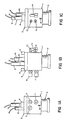
- Figs. 1a to 1c show an on-line wet chemical analyzer consisting of a complete sampling/reaction assembly as it would exist in an on-line process installation.
- the attachment of plumbing lines and tubing to the plurality of connections for introduction of fluids would be all that would be needed to make it ready for use.
- a manifold block 1 is the junction point for a plurality of connections for flows of fluid including sample inlet connection 7, siphon/waste connection 6, air vent connection 5, titrant connection 14, standard or calibrant connection 12, and reagent connection 13.
- a sampling reaction cell 2 Secured to the manifold block through the use of clamp knobs 4 and clamp rods 8 is a sampling reaction cell 2.
- a plurality of orifices in the manifold block 1 is provided for installing ion sensing probes 9, temperature sensing probes 10, and conductivity sensing probes 11.
- a clamp plate 3 is used to compress seals 19 (see Fig. 2) around the previously described probes 9, 10 and 11 to prevent leakage of liquids or air.
- Fig. 2 the remaining parts of the assembly are pictured, including the aforementioned seals 19, additional seals 16, to prevent leakage of liquids or air between the cell 2 and manifold 1, a magnetic stir bar 15 to agitate the captured sample during reaction or measurement, a drain/siphon fitting 17 used to establish the gravity siphon and leave a precise volume of sample in the cell and a titrant fitting 18 to introduce titrant required for the measurement. All of the items described are constructed of materials inert to the sample stream and which are such as to minimize deterioration and clogging and increase service life and reliability.
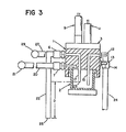
- Fig. 3 cell 2 and manifold 1 are shown in section, with siphon/waste fitting 17 and titrant fitting 18 extending into the cell.
- Sample inlet piping 20 extends from a process stream connection (not shown), through valve 21, to sample inlet fitting 7.
- Siphon/drain piping 22 extends from siphon/waste connection 6, to a distance, D, below the inlet opening to siphon/waste fitting 17 within the cell, D, being selected to establish a pressure differential between the inlet 23 of siphon/drain fitting 17 and the outlet 25 of siphon/drain piping 22 sufficient to start and maintain gravity siphon flow, as will be described below, e.g., a pressure differential of about 6 inches of water.
- Titrant piping 24 delivers titrating fluid from a source, through a metering pump, and into the cell via titrant connection 14 and fitting 18.
- the vent line from the cell to fitting 5 lies behind the siphon/drain line and is omitted for clarity.
- the vent line terminates in vent piping 27 and valve 29, which may be level, as shown, or elevated.
- the internal lines from standard and reagent fittings 12, 13, and the internal components of probes and sensors 9, 11 are also omitted for clarity.
- the sample valve 21 is opened, causing pressurized sample 30 to flow via inlet piping 20 from the liquid process stream.
- the vent valve 29 is kept open as sample 30 fills the cell from the bottom, displacing entrapped air through the vent piping 27 and valve 29, and also through the siphon/waste piping 22, until the cell is about half full, with the liquid level 32 above the inlet end 23 of the siphon/waste fitting 17 (Fig. 3b). This is typically determined by time, based on the volume flow rate through sample inlet piping 20, as programmed into the CPU microprocessor by operating personnel.
- vent valve 29 is then closed as pressurized sample continues to flow through inlet piping 20 into cell 2.
- excess sample 30 is forced to flow out of the cell through siphon/drain piping 22 (Fig. 3c).
- the sample valve 21 is closed to stop flow of sample into the cell.
- the air vent valve 29 is also in closed position at this point, so all flow is stopped (Fig. 3d).
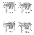
- the open air vent valve and exposed inlet end of the siphon/drain line in the cell allow the drain line to empty (Fig. 3g), leaving a captured sample of liquid of volume repeatable, e.g., within ⁇ 1/2%, from sample to sample.
- the volume of cell 2 and the sample volume captured are selected on the basis of the process to be monitored, and the nature of the testing to be performed.
- the cell volume may be 40 ml, and the captured sample volume 20 ml, or the cell volume may be 70 ml, and the captured sample volume 8 ml, e.g., where the process liquid is concentrated, and relatively larger volumes of additives are required.
- a measured volume accurate to about ⁇ 1% with a standard titrant pump, of titrant or reagent, or both, are added into the cell.
- a chemical reaction may be induced, and the desired characteristic or component measured, typically for variation from a standard.
- the cell was shown as initially empty. Typically, however, the reacted sample liquid from the previous cycle must be purged from the cell before the next sample is taken. Due to the addition of titrant during testing of the previous sample, the liquid level in the cell is above the inlet of the siphon/drain fitting, e.g., in a system for capturing a sample volume of 8 ml, the final test volume in the cell may be 40 to 50 ml.
- Flow of liquid through the siphon/drain conduit is established by opening the sample inlet valve 21 with the vent valve 29 closed. Vent valve 29 is then opened and sample inlet valve 21 is closed. Gravity siphon flow through the siphon drain fitting 17 and piping 22 continues until only the capture volume remains in the cell. The condition established in Fig. 3c is maintained to statistically purge the volume of sample remaining in the cell, e.g., six to eight volume exchanges are typically sufficient to provide a captured sample that is better than 95% clean.
- a calibrating liquid is allowed to flow into cell 2.
- the calibrating liquid is captured in the same manner as the volume of sample described above.
- the addition of reagent or titrant is carried out in the same manner.
- Measurement of the calibrating liquid characteristic or component allows for recalibration of the electrodes, sensors and probes to correct for change in the system, as typically will occur over time. It also allows the operator to compare on-line process readings with a periodic reading on a sample of known characteristic. Examples of processes where this is of particular value include:
- Caustic scrubber e.g., sodium hydroxide
- a batch holding tank through pipes in petrochemical plants to remove, i.e., "scrub", dangerous chemicals leaking from pipe valves and fittings.
- concentration of caustic solution in the batch tank is monitored to ensure effective and efficient maintenance of a safe operating environment within the plant.
- the concentration of the caustic solution is reduced due to the intended chemical reaction of the caustic with chemicals in the pipes and the dissolution of additional scrubbed chemicals.
- the initial concentration of the NaOH is about 20 percent and the operation continues until the NaOH becomes ineffective at some low concentration, e.g., about 2-5 percent.
- the process is then stopped and the holding tank is replenished with fresh solution. Since scrubbing is carried out continuously, a second holding tank is kept ready for use when the first tank is being recharged.
- vent valve 29 open, sample valve 21 is opened allowing NaOH to flow through sample inlet piping 20 into the volume of cell 2.
- vent valve 29 is closed to cause flow of liquid through fitting 17 and siphon/drain piping 22.
- sample inlet valve 21 is closed and all flow stops.
- Vent valve 29 is opened and excess sample fluid flows through siphon/drain piping 22 and fitting 17 from the volume of cell 2 by gravity siphon action until the level of liquid in the cell drops below the inlet end 23 of fitting 17, at which point siphon is interrupted, and the liquid in fitting 17 and siphon/drain piping 22 empties from outlet 25.
- a captured sample of repeatable volume e.g., 8 ml.
- a titrate of 3N (Normal) hydrochloric acid (HC1) is metered into the cell via titrant piping 24, connection 14 and fitting 18, within the cell, until the predetermined electrochemical potential, i.e., endpoint, of the reaction is reached.
- the CPU microprocessor derives the concentration of the NaOH caustic solution and stores the result, as well as sending the result to process display or recorder devices via any of several standard industrial signal devices.
- the analysis is thus fully automated and can be repeated on a frequency programmed by the operator.
- the arrangement of this invention is further of use, for example, in the power and utility industry, pulp and paper, food and beverage and chemical/petrochemical industries as well as in the petroleum, plating, dairying, rubber and plastics, primary metals, stone, clay and glass, textile and pharmaceutical industries; in fact, in any industry involving use of liquid media whose composition it is important to monitor in order to determine if a process liquid is used, depleted or changed in composition during an industrial process and/or when it is discharged to the environment.
- the arrangement of the present invention may be used, more specifically, for example, in analyses using sensing probes to monitor composition of liquids.
- the siphon action of the arrangement may also be modified to capture precise sizes of sample for use in instruments where other sensing methods are employed and the applicability of the present invention is independent of the sensing technology used. These methods may include, but are not limited to, amperometric, colourimetric and spectrophotometric methods.
- the arrangement may be used to condition and/or dilute a sample before analysis, as well as to ensure precision of sample volume.
- the vent may be connected to a source of inert or other gas, rather than being open to the atmosphere, or the vent may be pressurized and the system operated at superatmospheric pressure.
- the system may include liquid flow and liquid level sensors for controlling operation of valves, and a dump valve may be provided at the bottom of the cell for ease in purging.
Abstract
Description
- This invention relates generally to on-line process instruments or systems for monitoring the composition of liquid media in a process plant. More particularly, the invention consists of a chemical analyzer device for determination of a characteristic of a liquid process stream by wet chemical analysis to enable control of the process, said device comprising a sample cell for collection of a predetermined volume of sample to be analyzed and means for performing wet chemical analysis on the sample by progressively adding to the sample a measured flow of liquid reagent to cause progressive reaction with sample while sensing a parameter of the liquid sample as the reaction with the reagent proceeds.
- Process instruments are used to perform chemical analyses in multi-stage processes to ensure product quality is maintained and to save energy and raw material. These benefits result from operating within closer tolerances and from the quicker corrective response to inefficient conditions. Process instrument hardware for evaluation of liquid media is typically divided into two general categories based, in part, on whether the sampling of an accurate volume of liquid is important in the measurement process and whether the sample is conditioned. Instruments directly in the process stream, i.e., "in-line", do not condition the sample, nor do they need an accurate volume of sample for testing since they are always subject to the same flow cross-section of liquid. The information supplied by these instruments is continuous, but precision and accuracy are low. Examples of such types of instruments are pH electrodes, ion-selective electrodes, oxidation-reduction potential electrodes, and specific gravity and conductivity instruments.
- The second category of instruments consists typically of laboratory-type equipment ruggedized for industrial application. In these special process instruments, often referred to as "on-line", the liquid sample is removed from the process stream, conditioned to standard test conditions by reducing pressure and temperature, filtered to remove contaminants and solids, transferred as a known volume to a second cell in the instrument and reacted with chemicals prior to measurement of a specific component or characteristic. The data from this type of instrument is discrete, being obtained at intervals of from one to twenty minutes, with precision and accuracy comparable to that obtained in a chemical laboratory. The need to make operation automatic and the hardware particularly rugged are the significant differences from instruments designed solely for laboratory use, but these instruments still require a sophisticated operator in order to obtain proper test results. Examples of this type of instrument are titrators and colourimeters. Titrators and their use in chemical determinations are described generally in "Process Instruments and Controls Handbook", Third Edition (1985), Editor-in-Chief, Douglas M. Considine at p.6.98 et seq. FR-A-2506 453 describes a device for the determination of a quantity of liquid using, amongst other means, a siphon/drain conduit.
- Objectives of the present invention include: to provide an on-line instrument capable of capturing a liquid sample from a process stream, for measurement of a characteristic with high repeatability; to provide an on-line instrument capable of precision, accuracy and reliability without complex interconnected assemblies and delicate precision parts typical of laboratory-type on line instruments; and to provide an on-line instrument capable of reliable operation while interfacing with process environments with difficult conditions of temperature, chemical composition or contamination.
- According to the invention it is realized that increase in precision of repeatedly capturing a small volume of liquid can be achieved by employing a downwardly directed drain inlet precisely located at the desired liquid level of a chamber and applying pressure conditions to cause flow of excess liquid upwardly from the captured volume until the liquid level reaches the inlet and entry of air distrupts the liquid-transfer effect. It is found that, by establishing the level in this way, the wettability of the substance defining the inlet does not substantially affect the accuracy of the level achieved, hence an unusually accurate volume can be repeatedly achieved, despite differences in the character of the liquid from one sample to another. In the case of a 10 ml sample, accuracies of 1% repeatability can be achieved, in which 1% may represent only one small drop.
- According to the invention there is provided a chemical analyser device as mentioned before,
- characterised by the further inclusion in said device of
- a siphon cell having a closed volume that serves as said sample cell,
- sample inlet conduit means for delivery of a flow of process liquid into said cell,
- vent means for flow of vent gas into said cell,
- a siphon/drain conduit means having an inlet and an outlet, said conduit means having a first end defining said inlet downwardly disposed within the volume of said cell with said inlet at a predetermined level spaced from the bottom and top of said cell, the partial volume of said cell below said inlet sized to define a predetermined volume of sample to be analyzed, and the partial volume of said cell above the level of the inlet enabling additional liquid to be introduced into said cell during the operation of said device, and said siphon/drain conduit means having a second end defining said outlet downwardly disposed outside said cell with said outlet disposed at a predetermined distance below said inlet,
- means for causing flow of process liquid through said sample inlet conduit means into said cell to collect a sample in said cell and establish a level of liquid in said cell above the inlet of said siphon/drain conduit means,
- means for establishing flow of excess process liquid out of said cell volume through said siphon/drain conduit means, to cause said siphon/drain conduit means to fill,
- means for ceasing flow through said sample inlet conduit means,
- means for creating siphoning flow through said siphon/drain conduit means to drain excess process liquid from said cell in the manner that siphoning flow ceases automatically when the level of process liquid in said cell volume reaches the level of said inlet of said siphon/drain conduit means, thereby to define, in said cell, a sample of predetermined repeatable volume, and
- said means for performing wet chemical analysis constructed to perform said analysis in situ within said siphon cell by titrating techniques, comprising means for progressively delivering into said siphon cell a measured flow of liquid reagent to cause progressive reaction with sample in situ in said cell, and means for sensing in situ in said siphon cell a parameter of the liquid sample as the reaction with the reagent proceeds.
- In a preferred embodiment said means for causing flow of process liquid through said sample inlet conduit means into said cell may be constructed and positioned so that, after collecting a sample in said cell and establishing a level of liquid in said cell above the inlet of said siphon/drain conduit means, by continued flow of liquid into said cell volume via said sample inlet conduit means a flow of excess process liquid out of said cell volume through said siphon/drain conduit means is established to cause said siphon/drain conduit means to fill.
- Moreover, said means for creating siphoning flow may comprise means for continuing flow of liquid to establish flow of excess process liquid out of said cell volume through said siphon/drain conduit means. Also, said means for creating siphoning flow may comprise means for applying suction to said outlet.
- The means for sensing may comprise an ion sensing probe and/or a temperature sensing probe and/or a conductivity sensing probe. The chemical analyser may further comprise a stir bar positioned within said cell.
- According to another aspect of the invention, there is provided a method for determination of a characteristic of a liquid process stream by wet chemical analysis to enable control of said process, comprising the steps of (a) defining a predetermined volume of sample to be analyzed and (b) performing said wet chemical analysis on said sample by progressively adding to said sample a measured flow of liquid reagent to cause progressive reaction with said sample while sensing a parameter of the liquid sample as said reaction with said reagent proceeds,
characterised in that said step (a) of defining said volume of sample to be analyzed comprises providing a siphon cell having a closed volume, sample inlet conduit means for delivery of a flow of process liquid into said cell, vent means for flow of vent gas into said cell, and a siphon/drain conduit means having an inlet and an outlet, said conduit means having a first end defining said inlet downwardly disposed within the volume of said cell with said inlet at a predetermined level spaced from the bottom and top of said cell, the partial volume of said cell below said inlet sized to define a predetermined volume of sample to be analyzed, and the partial volume of said cell above the level of the inlet enabling additional liquid to be introduced into said cell in the performance of said method, and said conduit means having a second end defining said outlet downwardly disposed outside said cell with said outlet disposed at a predetermined distance below said inlet, - causing a flow of process liquid through said sample inlet conduit means into said cell to collect a sample in said cell and establish a level of liquid in said cell above the inlet of said siphon/drain conduit means,
- continuing to cause flow of said liquid into said volume via said sample inlet conduit means to establish flow of excess process liquid out of said cell volume through said drain/siphon conduit means, filling said drain/siphon conduit,
- after said drain/siphon conduit is filled, ceasing all flow through said sample inlet conduit means and creating siphoning flow through said siphon/drain conduit means to drain excess process liquid from said cell, said siphoning flow ceasing automatically when the level of process liquid in said cell volume reaches the level of said inlet of said siphon/drain conduit, thereby defining, in said cell, a sample of predetermined repeatable volume, and conducting said step (b) of performing said wet chemical analysis in situ within said siphon cell comprising, by titrating techniques, progressively delivering into said siphon cell a measured flow of liquid reagent to cause progressive reaction with said sample in situ in said cell, while sensing in situ in said siphon cell a parameter of the liquid sample as said reaction with said reagent proceeds.
- The sample may be taken directly from the liquid process stream of an industrial plant, the pressure of said stream serving to produce said flow of process liquid through said inlet conduit means into said cell and into said drain/siphon conduit.
- The present invention is particularly directed to an improved arrangement of hardware for removing a sample from the process stream, capturing a precise repeatable volume of the sample liquid and allowing a controlled chemical reaction to occur involving the sample in the same hardware prior to measurements being made on the reacted sample. The design of the device to be used according to the present invention eliminates the need for: (1) accurate and precise sample metering pumps; or (2) valving arrangements or other complex fluid handling equipment to capture a precise volume of the sample. The invention uses a very simple arrangement of a partially pressurized cell and gravity activated siphon and so is a relatively simple system lacking parts which are prone to failure when in contact with a sample stream.
- In preferred practice, the parts that are included in the instrument of the present invention include: (1) means for on-line sampling of the process stream in a volumetrically precise and repeatable manner at predetermined intervals; (2) means for introducing reagents to the reaction cell to condition the sample; (3) means for introducing a titrant relevant to the measurement to be made to the reaction cell; and (4) means for introducing a calibrant into the reaction cell in place of the sample in a volumetrically precise and repeatable manner such that it can be analyzed to correct for changes in the measuring instrument and this assembly.
- For a better understanding of the invention and to show how the same can be carried into effect, reference will now be made, by way of example only, to the accompanying drawings, wherein:
- Figs. 1a to 1c are elevations of sides at right angles to each other viewed in turn of an assembled sampling reaction cell/manifold for a device embodying this invention, with all parts in place;
- Fig. 2 is an exploded view of the sampling/reaction cell/manifold combination of Figs. 1a to 1c with all relevant parts shown;
- Fig. 3 is a side elevation, taken in section, of the assembled sampling reaction cell/manifold of the invention; and
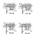
- Figs. 3a through 3h are sequential side elevations, taken in section, of the sample capture process of the invention.
- Referring now to the drawings, Figs. 1a to 1c show an on-line wet chemical analyzer consisting of a complete sampling/reaction assembly as it would exist in an on-line process installation. The attachment of plumbing lines and tubing to the plurality of connections for introduction of fluids would be all that would be needed to make it ready for use. As shown, a manifold block 1 is the junction point for a plurality of connections for flows of fluid including
sample inlet connection 7, siphon/waste connection 6,air vent connection 5,titrant connection 14, standard orcalibrant connection 12, andreagent connection 13. Secured to the manifold block through the use ofclamp knobs 4 and clamp rods 8 is asampling reaction cell 2. A plurality of orifices in the manifold block 1 is provided for installingion sensing probes 9,temperature sensing probes 10, andconductivity sensing probes 11. Aclamp plate 3 is used to compress seals 19 (see Fig. 2) around the previously describedprobes - In Fig. 2, the remaining parts of the assembly are pictured, including the
aforementioned seals 19,additional seals 16, to prevent leakage of liquids or air between thecell 2 and manifold 1, a magnetic stir bar 15 to agitate the captured sample during reaction or measurement, a drain/siphon fitting 17 used to establish the gravity siphon and leave a precise volume of sample in the cell and atitrant fitting 18 to introduce titrant required for the measurement. All of the items described are constructed of materials inert to the sample stream and which are such as to minimize deterioration and clogging and increase service life and reliability. - The operation of this arrangement, which preferably is preformed by a CPU microprocessor programed for the task, is as follows, with reference to Figs. 3 and 3a through 3h.
- In Fig. 3,
cell 2 and manifold 1 are shown in section, with siphon/waste fitting 17 andtitrant fitting 18 extending into the cell.Sample inlet piping 20 extends from a process stream connection (not shown), throughvalve 21, to sampleinlet fitting 7. Siphon/drain piping 22 extends from siphon/waste connection 6, to a distance, D, below the inlet opening to siphon/waste fitting 17 within the cell, D, being selected to establish a pressure differential between theinlet 23 of siphon/drain fitting 17 and theoutlet 25 of siphon/drain piping 22 sufficient to start and maintain gravity siphon flow, as will be described below, e.g., a pressure differential of about 6 inches of water. Titrant piping 24 delivers titrating fluid from a source, through a metering pump, and into the cell viatitrant connection 14 andfitting 18. The vent line from the cell to fitting 5 (Fig. 1a) lies behind the siphon/drain line and is omitted for clarity. The vent line terminates in vent piping 27 andvalve 29, which may be level, as shown, or elevated. The internal lines from standard andreagent fittings sensors - Referring to Fig. 3a, with the
vent valve 29 open, typically to the atmosphere, thesample valve 21 is opened, causing pressurized sample 30 to flow via inlet piping 20 from the liquid process stream. Thevent valve 29 is kept open as sample 30 fills the cell from the bottom, displacing entrapped air through the vent piping 27 andvalve 29, and also through the siphon/waste piping 22, until the cell is about half full, with theliquid level 32 above theinlet end 23 of the siphon/waste fitting 17 (Fig. 3b). This is typically determined by time, based on the volume flow rate through sample inlet piping 20, as programmed into the CPU microprocessor by operating personnel. - The
vent valve 29 is then closed as pressurized sample continues to flow through inlet piping 20 intocell 2. As the cell volume is now closed, excess sample 30 is forced to flow out of the cell through siphon/drain piping 22 (Fig. 3c). After the siphon/drain piping is filled, thesample valve 21 is closed to stop flow of sample into the cell. Theair vent valve 29 is also in closed position at this point, so all flow is stopped (Fig. 3d). - The
air vent valve 29 is then reopened, allowing flow of the sample liquid held in the siphon/drain fitting 17 and piping 22 (Fig. 3e). The gravity siphon action continues until theliquid level 32 of sample incell 2 falls below theinlet end 23 of siphon/waste fitting 17, opening the inlet end of the tube to air in the cell, breaking siphon and leaving a precisely repeatable volume of sample liquid remaining in the cell (Fig. 3f), - The open air vent valve and exposed inlet end of the siphon/drain line in the cell allow the drain line to empty (Fig. 3g), leaving a captured sample of liquid of volume repeatable, e.g., within ± 1/2%, from sample to sample. (The volume of
cell 2 and the sample volume captured are selected on the basis of the process to be monitored, and the nature of the testing to be performed. For example, the cell volume may be 40 ml, and the capturedsample volume 20 ml, or the cell volume may be 70 ml, and the captured sample volume 8 ml, e.g., where the process liquid is concentrated, and relatively larger volumes of additives are required.) - At this point, depending on the characteristic or component to be determined and the test to be performed, a measured volume, accurate to about ± 1% with a standard titrant pump, of titrant or reagent, or both, are added into the cell. A chemical reaction may be induced, and the desired characteristic or component measured, typically for variation from a standard.
- In the process sequence described above, the cell was shown as initially empty. Typically, however, the reacted sample liquid from the previous cycle must be purged from the cell before the next sample is taken. Due to the addition of titrant during testing of the previous sample, the liquid level in the cell is above the inlet of the siphon/drain fitting, e.g., in a system for capturing a sample volume of 8 ml, the final test volume in the cell may be 40 to 50 ml. Flow of liquid through the siphon/drain conduit is established by opening the
sample inlet valve 21 with thevent valve 29 closed.Vent valve 29 is then opened andsample inlet valve 21 is closed. Gravity siphon flow through the siphon drain fitting 17 and piping 22 continues until only the capture volume remains in the cell. The condition established in Fig. 3c is maintained to statistically purge the volume of sample remaining in the cell, e.g., six to eight volume exchanges are typically sufficient to provide a captured sample that is better than 95% clean. - At appropriate intervals, e.g., after a predetermined number of process samples are run, a calibrating liquid is allowed to flow into
cell 2. The calibrating liquid is captured in the same manner as the volume of sample described above. The addition of reagent or titrant is carried out in the same manner. Measurement of the calibrating liquid characteristic or component allows for recalibration of the electrodes, sensors and probes to correct for change in the system, as typically will occur over time. It also allows the operator to compare on-line process readings with a periodic reading on a sample of known characteristic. Examples of processes where this is of particular value include: - Steady-state processes, such as maintenance of peroxide at optimum concentration in cotton fabric bleaching. As peroxide is continuously added (solution addition) and depleted (in bleaching action), the concentration changes over a fairly narrow range. At too high a concentration of peroxide, the fabric is damaged, and at too low a concentration, the fabric is inadequately treated. A sample taken at the optimum concentration, prepared to ease sample handling (e.g. filtered), provides a good calibrating solution.
- Depletion processes, such as plating copper onto inert medium in the manufacture of printed circuit boards. In this process, the copper concentration is constantly decreasing as the copper is deposited on the board. Monitoring can help prevent excessively low concentrations of copper, which result in unacceptably uneven coverage. For this process, an exact sample of the plating bath, including interfering additives, under conditions slightly above the minimum copper concentration situation gives maximum precision (through standardization) at the critical end of the process range, when additional copper must be added to the bath.
- Saturation processes, such as waste treatment in which copper ions in solution are precipitated out to prevent their discharge to the general environment. Typically, a chemical is added to cause this to occur, based on an assumed inflow of copper ions. During high-inflow periods, the solution can become overloaded with copper, requiring addition of greater amounts of the treating chemical. A calibrating liquid near this upper limit gives maximum precision.
- By way of example only, one specific testing procedure will now be described.
- Caustic scrubber, e.g., sodium hydroxide, is pumped from a batch holding tank through pipes in petrochemical plants to remove, i.e., "scrub", dangerous chemicals leaking from pipe valves and fittings. The concentration of caustic solution in the batch tank is monitored to ensure effective and efficient maintenance of a safe operating environment within the plant.
- As scrubbing proceeds, the concentration of the caustic solution is reduced due to the intended chemical reaction of the caustic with chemicals in the pipes and the dissolution of additional scrubbed chemicals. The initial concentration of the NaOH is about 20 percent and the operation continues until the NaOH becomes ineffective at some low concentration, e.g., about 2-5 percent. The process is then stopped and the holding tank is replenished with fresh solution. Since scrubbing is carried out continuously, a second holding tank is kept ready for use when the first tank is being recharged.
- The concentration of the caustic solution is analyzed by simple acid-based analysis to an endpoint, as sensed by a pH electrode, using the on-line wet chemical analyzer of the invention, as will now be described. With
vent valve 29 open,sample valve 21 is opened allowing NaOH to flow through sample inlet piping 20 into the volume ofcell 2. After a predetermined time, programmed into the associated CPU microprocessor, when the liquid level in the cell is above theinlet end 23 of siphon/drain fitting 17,vent valve 29 is closed to cause flow of liquid through fitting 17 and siphon/drain piping 22. After a volume of flow calculated to flush the previous sample from the cell and provide a new sample of desired cleanliness, e.g., 160 ml.,sample inlet valve 21 is closed and all flow stops. -
Vent valve 29 is opened and excess sample fluid flows through siphon/drain piping 22 and fitting 17 from the volume ofcell 2 by gravity siphon action until the level of liquid in the cell drops below theinlet end 23 of fitting 17, at which point siphon is interrupted, and the liquid in fitting 17 and siphon/drain piping 22 empties fromoutlet 25. - There remains within the cell a captured sample of repeatable volume, e.g., 8 ml., for analysis. To the captured sample there is added, via
reagent connection connection 14 and fitting 18, within the cell, until the predetermined electrochemical potential, i.e., endpoint, of the reaction is reached. - The CPU microprocessor derives the concentration of the NaOH caustic solution and stores the result, as well as sending the result to process display or recorder devices via any of several standard industrial signal devices.
- The analysis is thus fully automated and can be repeated on a frequency programmed by the operator.
- The arrangement of this invention is further of use, for example, in the power and utility industry, pulp and paper, food and beverage and chemical/petrochemical industries as well as in the petroleum, plating, dairying, rubber and plastics, primary metals, stone, clay and glass, textile and pharmaceutical industries; in fact, in any industry involving use of liquid media whose composition it is important to monitor in order to determine if a process liquid is used, depleted or changed in composition during an industrial process and/or when it is discharged to the environment.
- The arrangement of the present invention may be used, more specifically, for example, in analyses using sensing probes to monitor composition of liquids. The siphon action of the arrangement may also be modified to capture precise sizes of sample for use in instruments where other sensing methods are employed and the applicability of the present invention is independent of the sensing technology used. These methods may include, but are not limited to, amperometric, colourimetric and spectrophotometric methods. The arrangement may be used to condition and/or dilute a sample before analysis, as well as to ensure precision of sample volume.
- Other embodiments are within the following claims, for example, the vent may be connected to a source of inert or other gas, rather than being open to the atmosphere, or the vent may be pressurized and the system operated at superatmospheric pressure. The system may include liquid flow and liquid level sensors for controlling operation of valves, and a dump valve may be provided at the bottom of the cell for ease in purging.
Claims (8)
Priority Applications (1)
| Application Number | Priority Date | Filing Date | Title |
|---|---|---|---|
| AT86306855T ATE61477T1 (en) | 1985-09-06 | 1986-09-04 | SAMPLE CONTROL INSTRUMENT FOR ON-LINE USE. |
Applications Claiming Priority (2)
| Application Number | Priority Date | Filing Date | Title |
|---|---|---|---|
| GB8522126 | 1985-09-06 | ||
| GB858522126A GB8522126D0 (en) | 1985-09-06 | 1985-09-06 | Sample monitoring arrangement |
Publications (3)
| Publication Number | Publication Date |
|---|---|
| EP0214846A2 EP0214846A2 (en) | 1987-03-18 |
| EP0214846A3 EP0214846A3 (en) | 1989-03-15 |
| EP0214846B1 true EP0214846B1 (en) | 1991-03-06 |
Family
ID=10584807
Family Applications (1)
| Application Number | Title | Priority Date | Filing Date |
|---|---|---|---|
| EP86306855A Expired - Lifetime EP0214846B1 (en) | 1985-09-06 | 1986-09-04 | Sample monitoring instrument for on-line application |
Country Status (9)
| Country | Link |
|---|---|
| US (2) | US4910151A (en) |
| EP (1) | EP0214846B1 (en) |
| JP (1) | JPS6287860A (en) |
| AT (1) | ATE61477T1 (en) |
| CA (1) | CA1293912C (en) |
| DE (1) | DE3677859D1 (en) |
| GB (1) | GB8522126D0 (en) |
| HK (1) | HK75593A (en) |
| SG (1) | SG57493G (en) |
Families Citing this family (14)
| Publication number | Priority date | Publication date | Assignee | Title |
|---|---|---|---|---|
| JP2590943B2 (en) * | 1987-10-15 | 1997-03-19 | 三菱化学株式会社 | Weight titrator |
| FR2645966B1 (en) * | 1989-04-18 | 1991-06-07 | Commissariat Energie Atomique | INSTALLATION OF CONTINUOUS AND REAL-TIME MEASUREMENTS, METAL MASSES IN ACID SOLUTION, AND THE ACIDITY OF THIS SOLUTION |
| US5368817A (en) * | 1992-07-08 | 1994-11-29 | Toppan Printing, Co., Ltd. | Dampening water controller |
| US5565353A (en) * | 1994-06-22 | 1996-10-15 | Board Of Regents, The University Of Texas System | Perfusable culture device |
| US6178383B1 (en) * | 1998-04-15 | 2001-01-23 | Cargill, Incorporated | On-line sampling and image analyzer for determining solid content in a fluid media |
| US6210640B1 (en) * | 1998-06-08 | 2001-04-03 | Memc Electronic Materials, Inc. | Collector for an automated on-line bath analysis system |
| WO2001031313A1 (en) * | 1999-10-18 | 2001-05-03 | Siemens Plc | Apparatus for measuring water quality |
| US6846458B1 (en) | 1999-10-29 | 2005-01-25 | Rosemount Analytical Inc. | Process analytic system with improved sample handling system |
| NZ571749A (en) * | 2002-12-19 | 2009-09-25 | Lattec I S | A milk conveyance for milk sampling and cleaning of previous sample residue |
| US7162971B2 (en) | 2002-12-19 | 2007-01-16 | Lattec I/S | Milk conveyer device |
| US8748191B2 (en) * | 2010-08-02 | 2014-06-10 | Ecolab Usa Inc. | Stop-flow analytical systems and methods |
| US20140352412A1 (en) * | 2013-05-28 | 2014-12-04 | Metafix Inc. | Method and apparatus for measurement and control of process parameters |
| US11397171B2 (en) * | 2017-09-18 | 2022-07-26 | Ecolab Usa Inc. | Adaptive range flow titration systems and methods with sample conditioning |
| WO2021096885A1 (en) * | 2019-11-12 | 2021-05-20 | Siemens Healthcare Diagnostics Inc. | System with improved seal between a liquid container and a manifold |
Family Cites Families (17)
| Publication number | Priority date | Publication date | Assignee | Title |
|---|---|---|---|---|
| US618835A (en) * | 1899-02-07 | Frank bowen | ||
| US1144525A (en) * | 1913-12-09 | 1915-06-29 | William F Rogers | Diffusing apparatus. |
| US1235316A (en) * | 1916-05-22 | 1917-07-31 | Charles H Henderson | Automatic siphon-regulator. |
| US1574149A (en) * | 1924-01-24 | 1926-02-23 | Hompes Henry | Cream divider |
| US1564430A (en) * | 1925-01-30 | 1925-12-08 | Walter J Maddrell | Device for maintaining liquid levels |
| US2356013A (en) * | 1943-08-03 | 1944-08-15 | Rossi Irving | Continuous casting of metals |
| US2461334A (en) * | 1944-12-01 | 1949-02-08 | Servel Inc | Liquid treating unit |
| US2884942A (en) * | 1957-05-06 | 1959-05-05 | Jersey Prod Res Co | Apparatus for use in corrosion inhibitor injection |
| US3415267A (en) * | 1966-08-31 | 1968-12-10 | Cory Corp | Liquid supply apparatus |
| US3589385A (en) * | 1969-02-07 | 1971-06-29 | Cory Corp | Vented hot water supply apparatus |
| NO126935B (en) * | 1971-04-26 | 1973-04-09 | Norske Zinkkompani As | |
| AU453989B2 (en) * | 1971-12-07 | 1974-10-17 | Texaco Development Corporation | Acid analyzer |
| JPS4951976A (en) * | 1972-09-16 | 1974-05-20 | ||
| JPS5436878B2 (en) * | 1974-05-15 | 1979-11-12 | ||
| SU697925A1 (en) * | 1977-06-01 | 1979-11-15 | Всесоюзный Ордена Ленина И Ордена Дружбы Народов Научно-Исследовательский Институт Растениеводства Им. Н.И. Вавилова | Method of calibrating polarographic oxygen cell |
| US4310013A (en) * | 1980-03-24 | 1982-01-12 | Mcclaskey Billy M | Siphon device |
| FR2506453A1 (en) * | 1981-05-21 | 1982-11-26 | Europ Propulsion | Rocket liq. fuel tank filling process supplying preset mass - has inverted U=shaped syphon connected to overflow and fuel introduced at predetermined temp. until flow from tube occurs |
-
1985
- 1985-09-06 GB GB858522126A patent/GB8522126D0/en active Pending
-
1986
- 1986-09-04 EP EP86306855A patent/EP0214846B1/en not_active Expired - Lifetime
- 1986-09-04 DE DE8686306855T patent/DE3677859D1/en not_active Expired - Lifetime
- 1986-09-04 AT AT86306855T patent/ATE61477T1/en not_active IP Right Cessation
- 1986-09-05 CA CA000517533A patent/CA1293912C/en not_active Expired - Lifetime
- 1986-09-05 JP JP61209375A patent/JPS6287860A/en active Granted
-
1987
- 1987-04-14 US US07/038,221 patent/US4910151A/en not_active Expired - Lifetime
-
1988
- 1988-12-29 US US07/291,430 patent/US4911891A/en not_active Expired - Lifetime
-
1993
- 1993-05-04 SG SG574/93A patent/SG57493G/en unknown
- 1993-07-29 HK HK755/93A patent/HK75593A/en not_active IP Right Cessation
Also Published As
| Publication number | Publication date |
|---|---|
| EP0214846A3 (en) | 1989-03-15 |
| US4910151A (en) | 1990-03-20 |
| SG57493G (en) | 1993-07-09 |
| US4911891A (en) | 1990-03-27 |
| JPS6287860A (en) | 1987-04-22 |
| GB8522126D0 (en) | 1985-10-09 |
| EP0214846A2 (en) | 1987-03-18 |
| CA1293912C (en) | 1992-01-07 |
| HK75593A (en) | 1993-08-06 |
| ATE61477T1 (en) | 1991-03-15 |
| JPH048749B2 (en) | 1992-02-18 |
| DE3677859D1 (en) | 1991-04-11 |
Similar Documents
| Publication | Publication Date | Title |
|---|---|---|
| EP0214846B1 (en) | Sample monitoring instrument for on-line application | |
| US5364510A (en) | Scheme for bath chemistry measurement and control for improved semiconductor wet processing | |
| US8871080B2 (en) | Management system for an electrolyte analyzer | |
| US4852385A (en) | Maintenance device for at least partially automatic cleaning and calibration of a probe containing a measured value transmitter | |
| CN105738287B (en) | Water Test Kits | |
| CN104849422A (en) | Ammonia nitrogen on-line monitoring system and method thereof | |
| CN201392315Y (en) | Automatic on-line monitoring device for ammonia nitrogen | |
| JP3620856B2 (en) | Liquid sample inspection equipment | |
| CN111060561A (en) | Device, method and system for monitoring ph value of liquid | |
| CN108896629B (en) | Three-point flow type calibration device and method for sodium ion concentration meter | |
| US20040253737A1 (en) | Device and method for monitoring and regulating a process solution | |
| WO2006043900A1 (en) | A water quality testing system | |
| KR20010052578A (en) | Collector for an automated on-line bath analysis system | |
| EP1368643A2 (en) | Continuous flow titration | |
| JP2011220944A (en) | Automatic titration analyzer, automatic titration analysis method, automatic analysis management system of process liquid and automatic titration analysis method of process liquid | |
| KR20010072569A (en) | Automated chemical process control system | |
| JP2783449B2 (en) | Analyzer line control system | |
| JP2001296305A (en) | Sample solution automatic analyzing device and method | |
| JP6191404B2 (en) | Sludge activity measuring apparatus and sludge activity measuring method | |
| AU743103B2 (en) | Methods and apparatus for monitoring water process equipment | |
| US20080053204A1 (en) | Electrochemical Sensor | |
| KR100798053B1 (en) | Cod analyzer | |
| JP2007333611A (en) | Chemical analysis apparatus and chemical analysis method using same | |
| US5061634A (en) | Method for continually and automatically measuring the level of a water treatment product in boiler feedwater | |
| US6548022B1 (en) | Automatic analyzer |
Legal Events
| Date | Code | Title | Description |
|---|---|---|---|
| PUAI | Public reference made under article 153(3) epc to a published international application that has entered the european phase |
Free format text: ORIGINAL CODE: 0009012 |
|
| AK | Designated contracting states |
Kind code of ref document: A2 Designated state(s): AT BE CH DE FR GB IT LI LU NL SE |
|
| PUAL | Search report despatched |
Free format text: ORIGINAL CODE: 0009013 |
|
| AK | Designated contracting states |
Kind code of ref document: A3 Designated state(s): AT BE CH DE FR GB IT LI LU NL SE |
|
| 17P | Request for examination filed |
Effective date: 19890721 |
|
| 17Q | First examination report despatched |
Effective date: 19890920 |
|
| GRAA | (expected) grant |
Free format text: ORIGINAL CODE: 0009210 |
|
| AK | Designated contracting states |
Kind code of ref document: B1 Designated state(s): AT BE CH DE FR GB IT LI LU NL SE |
|
| REF | Corresponds to: |
Ref document number: 61477 Country of ref document: AT Date of ref document: 19910315 Kind code of ref document: T |
|
| ITF | It: translation for a ep patent filed |
Owner name: JACOBACCI & PERANI S.P.A. |
|
| REF | Corresponds to: |
Ref document number: 3677859 Country of ref document: DE Date of ref document: 19910411 |
|
| ET | Fr: translation filed | ||
| REG | Reference to a national code |
Ref country code: CH Ref legal event code: PFA Free format text: TYTRONICS INCORPORATED |
|
| ITPR | It: changes in ownership of a european patent |
Owner name: CAMBIO SEDE;TYTRONICS INCORPORATED |
|
| PLBE | No opposition filed within time limit |
Free format text: ORIGINAL CODE: 0009261 |
|
| STAA | Information on the status of an ep patent application or granted ep patent |
Free format text: STATUS: NO OPPOSITION FILED WITHIN TIME LIMIT |
|
| 26N | No opposition filed | ||
| EPTA | Lu: last paid annual fee | ||
| EAL | Se: european patent in force in sweden |
Ref document number: 86306855.7 |
|
| PGFP | Annual fee paid to national office [announced via postgrant information from national office to epo] |
Ref country code: LU Payment date: 20010905 Year of fee payment: 16 |
|
| REG | Reference to a national code |
Ref country code: GB Ref legal event code: IF02 |
|
| PG25 | Lapsed in a contracting state [announced via postgrant information from national office to epo] |
Ref country code: LU Free format text: LAPSE BECAUSE OF NON-PAYMENT OF DUE FEES Effective date: 20020904 |
|
| REG | Reference to a national code |
Ref country code: GB Ref legal event code: PE20 |
|
| PGFP | Annual fee paid to national office [announced via postgrant information from national office to epo] |
Ref country code: NL Payment date: 20051116 Year of fee payment: 20 Ref country code: GB Payment date: 20051116 Year of fee payment: 20 |
|
| PGFP | Annual fee paid to national office [announced via postgrant information from national office to epo] |
Ref country code: FR Payment date: 20051117 Year of fee payment: 20 |
|
| PGFP | Annual fee paid to national office [announced via postgrant information from national office to epo] |
Ref country code: AT Payment date: 20051121 Year of fee payment: 20 |
|
| PGFP | Annual fee paid to national office [announced via postgrant information from national office to epo] |
Ref country code: CH Payment date: 20051125 Year of fee payment: 20 Ref country code: SE Payment date: 20051125 Year of fee payment: 20 |
|
| PGFP | Annual fee paid to national office [announced via postgrant information from national office to epo] |
Ref country code: IT Payment date: 20051129 Year of fee payment: 20 |
|
| PGFP | Annual fee paid to national office [announced via postgrant information from national office to epo] |
Ref country code: DE Payment date: 20051130 Year of fee payment: 20 |
|
| PGFP | Annual fee paid to national office [announced via postgrant information from national office to epo] |
Ref country code: BE Payment date: 20051208 Year of fee payment: 20 |
|
| PG25 | Lapsed in a contracting state [announced via postgrant information from national office to epo] |
Ref country code: GB Free format text: LAPSE BECAUSE OF EXPIRATION OF PROTECTION Effective date: 20060903 |
|
| PG25 | Lapsed in a contracting state [announced via postgrant information from national office to epo] |
Ref country code: NL Free format text: LAPSE BECAUSE OF EXPIRATION OF PROTECTION Effective date: 20060904 |
|
| REG | Reference to a national code |
Ref country code: CH Ref legal event code: PL |
|
| NLV7 | Nl: ceased due to reaching the maximum lifetime of a patent |
Effective date: 20060904 |
|
| EUG | Se: european patent has lapsed | ||
| BE20 | Be: patent expired |
Owner name: *TYTRONICS INC. Effective date: 20060904 |