EP0214729B1 - Bearing structures - Google Patents
Bearing structures Download PDFInfo
- Publication number
- EP0214729B1 EP0214729B1 EP86305562A EP86305562A EP0214729B1 EP 0214729 B1 EP0214729 B1 EP 0214729B1 EP 86305562 A EP86305562 A EP 86305562A EP 86305562 A EP86305562 A EP 86305562A EP 0214729 B1 EP0214729 B1 EP 0214729B1
- Authority
- EP
- European Patent Office
- Prior art keywords
- bearing
- air
- structure according
- rotatable member
- stationary member
- Prior art date
- Legal status (The legal status is an assumption and is not a legal conclusion. Google has not performed a legal analysis and makes no representation as to the accuracy of the status listed.)
- Expired - Lifetime
Links
Images


Classifications
-
- G—PHYSICS
- G01—MEASURING; TESTING
- G01B—MEASURING LENGTH, THICKNESS OR SIMILAR LINEAR DIMENSIONS; MEASURING ANGLES; MEASURING AREAS; MEASURING IRREGULARITIES OF SURFACES OR CONTOURS
- G01B5/00—Measuring arrangements characterised by the use of mechanical techniques
- G01B5/0002—Arrangements for supporting, fixing or guiding the measuring instrument or the object to be measured
- G01B5/0004—Supports
-
- B—PERFORMING OPERATIONS; TRANSPORTING
- B23—MACHINE TOOLS; METAL-WORKING NOT OTHERWISE PROVIDED FOR
- B23Q—DETAILS, COMPONENTS, OR ACCESSORIES FOR MACHINE TOOLS, e.g. ARRANGEMENTS FOR COPYING OR CONTROLLING; MACHINE TOOLS IN GENERAL CHARACTERISED BY THE CONSTRUCTION OF PARTICULAR DETAILS OR COMPONENTS; COMBINATIONS OR ASSOCIATIONS OF METAL-WORKING MACHINES, NOT DIRECTED TO A PARTICULAR RESULT
- B23Q1/00—Members which are comprised in the general build-up of a form of machine, particularly relatively large fixed members
- B23Q1/25—Movable or adjustable work or tool supports
- B23Q1/26—Movable or adjustable work or tool supports characterised by constructional features relating to the co-operation of relatively movable members; Means for preventing relative movement of such members
- B23Q1/38—Movable or adjustable work or tool supports characterised by constructional features relating to the co-operation of relatively movable members; Means for preventing relative movement of such members using fluid bearings or fluid cushion supports
-
- B—PERFORMING OPERATIONS; TRANSPORTING
- B23—MACHINE TOOLS; METAL-WORKING NOT OTHERWISE PROVIDED FOR
- B23Q—DETAILS, COMPONENTS, OR ACCESSORIES FOR MACHINE TOOLS, e.g. ARRANGEMENTS FOR COPYING OR CONTROLLING; MACHINE TOOLS IN GENERAL CHARACTERISED BY THE CONSTRUCTION OF PARTICULAR DETAILS OR COMPONENTS; COMBINATIONS OR ASSOCIATIONS OF METAL-WORKING MACHINES, NOT DIRECTED TO A PARTICULAR RESULT
- B23Q1/00—Members which are comprised in the general build-up of a form of machine, particularly relatively large fixed members
- B23Q1/25—Movable or adjustable work or tool supports
- B23Q1/44—Movable or adjustable work or tool supports using particular mechanisms
- B23Q1/50—Movable or adjustable work or tool supports using particular mechanisms with rotating pairs only, the rotating pairs being the first two elements of the mechanism
- B23Q1/52—Movable or adjustable work or tool supports using particular mechanisms with rotating pairs only, the rotating pairs being the first two elements of the mechanism a single rotating pair
- B23Q1/522—Movable or adjustable work or tool supports using particular mechanisms with rotating pairs only, the rotating pairs being the first two elements of the mechanism a single rotating pair which is perpendicular to the working surface
-
- F—MECHANICAL ENGINEERING; LIGHTING; HEATING; WEAPONS; BLASTING
- F16—ENGINEERING ELEMENTS AND UNITS; GENERAL MEASURES FOR PRODUCING AND MAINTAINING EFFECTIVE FUNCTIONING OF MACHINES OR INSTALLATIONS; THERMAL INSULATION IN GENERAL
- F16C—SHAFTS; FLEXIBLE SHAFTS; ELEMENTS OR CRANKSHAFT MECHANISMS; ROTARY BODIES OTHER THAN GEARING ELEMENTS; BEARINGS
- F16C17/00—Sliding-contact bearings for exclusively rotary movement
- F16C17/26—Systems consisting of a plurality of sliding-contact bearings
-
- F—MECHANICAL ENGINEERING; LIGHTING; HEATING; WEAPONS; BLASTING
- F16—ENGINEERING ELEMENTS AND UNITS; GENERAL MEASURES FOR PRODUCING AND MAINTAINING EFFECTIVE FUNCTIONING OF MACHINES OR INSTALLATIONS; THERMAL INSULATION IN GENERAL
- F16C—SHAFTS; FLEXIBLE SHAFTS; ELEMENTS OR CRANKSHAFT MECHANISMS; ROTARY BODIES OTHER THAN GEARING ELEMENTS; BEARINGS
- F16C32/00—Bearings not otherwise provided for
- F16C32/06—Bearings not otherwise provided for with moving member supported by a fluid cushion formed, at least to a large extent, otherwise than by movement of the shaft, e.g. hydrostatic air-cushion bearings
- F16C32/0603—Bearings not otherwise provided for with moving member supported by a fluid cushion formed, at least to a large extent, otherwise than by movement of the shaft, e.g. hydrostatic air-cushion bearings supported by a gas cushion, e.g. an air cushion
-
- F—MECHANICAL ENGINEERING; LIGHTING; HEATING; WEAPONS; BLASTING
- F16—ENGINEERING ELEMENTS AND UNITS; GENERAL MEASURES FOR PRODUCING AND MAINTAINING EFFECTIVE FUNCTIONING OF MACHINES OR INSTALLATIONS; THERMAL INSULATION IN GENERAL
- F16C—SHAFTS; FLEXIBLE SHAFTS; ELEMENTS OR CRANKSHAFT MECHANISMS; ROTARY BODIES OTHER THAN GEARING ELEMENTS; BEARINGS
- F16C32/00—Bearings not otherwise provided for
- F16C32/06—Bearings not otherwise provided for with moving member supported by a fluid cushion formed, at least to a large extent, otherwise than by movement of the shaft, e.g. hydrostatic air-cushion bearings
- F16C32/0681—Construction or mounting aspects of hydrostatic bearings, for exclusively rotary movement, related to the direction of load
- F16C32/0692—Construction or mounting aspects of hydrostatic bearings, for exclusively rotary movement, related to the direction of load for axial load only
-
- F—MECHANICAL ENGINEERING; LIGHTING; HEATING; WEAPONS; BLASTING
- F16—ENGINEERING ELEMENTS AND UNITS; GENERAL MEASURES FOR PRODUCING AND MAINTAINING EFFECTIVE FUNCTIONING OF MACHINES OR INSTALLATIONS; THERMAL INSULATION IN GENERAL
- F16C—SHAFTS; FLEXIBLE SHAFTS; ELEMENTS OR CRANKSHAFT MECHANISMS; ROTARY BODIES OTHER THAN GEARING ELEMENTS; BEARINGS
- F16C2322/00—Apparatus used in shaping articles
- F16C2322/39—General buildup of machine tools, e.g. spindles, slides, actuators
-
- Y—GENERAL TAGGING OF NEW TECHNOLOGICAL DEVELOPMENTS; GENERAL TAGGING OF CROSS-SECTIONAL TECHNOLOGIES SPANNING OVER SEVERAL SECTIONS OF THE IPC; TECHNICAL SUBJECTS COVERED BY FORMER USPC CROSS-REFERENCE ART COLLECTIONS [XRACs] AND DIGESTS
- Y10—TECHNICAL SUBJECTS COVERED BY FORMER USPC
- Y10S—TECHNICAL SUBJECTS COVERED BY FORMER USPC CROSS-REFERENCE ART COLLECTIONS [XRACs] AND DIGESTS
- Y10S310/00—Electrical generator or motor structure
- Y10S310/06—Printed-circuit motors and components
Definitions
- This invention relates to bearing structures particularly for use in metrological apparatus, such as rate tables, angular measuring systems and apparatus for the measurement of profile errors including roundness, straightness and surface texture. More particularly, the invention relates to bearing structures comprising a stationary member, and a rotatable member for supporting a workpiece support member for rotation about a vertical axis relative to said stationary member, a first air bearing between said rotatable member and said stationary member and operable to constrain said rotatable member against downwards axial movement relative to said stationary member, a second air bearing acting between said rotatable member and said stationary member and operable to constrain said rotatable member against upwards axial movement relative to said stationary member, conduit means for supplying air to said air bearings for operation thereof, and a third bearing acting between said rotatable member and said stationary member and constraining said rotatable member against radial movement relative to said stationary member.
- the bearing structure according to the invention is characterised in that the third bearing is a dry low-friction bearing and the first air bearing has a higher stiffness than the second air bearing.
- Oil hydrostatic bearings have also been proposed.
- oil is continuously pumped into the space between conical surfaces provided on the shaft and a surrounding stationary support member.
- this type of bearing is capable of supporting high loads, it is extremely expensive as it requires a considerable amount of ancilliary equipment such as a pump, a reservoir for the oil and associated piping.
- the metrological apparatus which is particularly for measuring roundness, comprises a bench 2 within which is a chassis structure (not shown) supporting a tumt- able 4 by means of a bearing to be described in detail with reference to Figs. 2 to 5.
- the turntable 4 is for supporting a workpiece whose surface is to be measured.
- a column 6 is also supported on the chassis structure adjacent the turntable 4.
- a carriage 8 is mounted on the column 6 for vertical movement and supports a transducer (not shown), which may for example be inductive, to which a stylus 10 is connected.
- a workpiece is mounted on the turntable 4 so that it may be rotated, by rotation of the turntable 4, relative to the stylus 10 which is positioned in contact with the workpiece surface to be measured.
- a non-contact transducer may be employed.
- the apparatus also includes signal processing means (not shown) for processing the signal output by the transducer in order to provide information as to the characteristics, such as the roundness, of the workpiece.
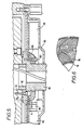
- the bearing structure upon which the turntable 4 is mounted is shown in section in Fig. 2. It comprises a rotor 12 supported for rotation about a vertical axis-by a stator 14 which is fixed relative to the chassis of the apparatus indicated diagrammatically at 16.
- the rotor 12 comprises a spindle 18 and upper and lower discs 20, 22 secured to the spindle 18 by bolts 24 and 26 (only one each of which is shown in Fig. 2).
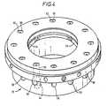
- the stator comprises a member 28, which is also shown in Figs. 3 and 4, having a cylindrical bore 30 in which the spindle 18 is located.
- An annular recess 32 is formed in the bore 30 near to the upper end and contains three dry friction bearing elements 34, 36 and 38 which are made of a low friction plastics material, such as an acetal copolymer with a PTFE filler and which engage an annular shoulder 40 formed on the spindle 18, to constrain the spindle against radial movement.
- the elements 34, 36 and 38 are disposed at equiangularly spaced positions and are secured in place by bolts 42.
- the element 38 includes two thin portions 38a which permit the central portion 38b to move radially.
- An adjusting screw 44 and compression spring 46 are arranged in the member 28 for adjusting the force with which the centre portion 38b of the element 38 is pressed against the spindle 18.
- the elements 34 36 and 38 accurately define the radial position of the spindle 18 whilst permitting the spindle 18 to rotate relative to the member 28.
- the stator 14 includes a further member 48 which is secured to and surrounds the lower portion of the member 28.
- An annular air supply channel 50 is defined between the members 28 and 48 and is connected to an air supply line 52 through a radial bore 54 formed in the member 48.
- the channel 50 is connected to the space 56 between the upper, radially extending surface of the member 28 and the lower, radially extending surface of the disc 20 through blind radial bores 58 and upwardly directed bores 60 formed in the member 28 to form an air bearing in the radially extending space between the upper surface of the member 28 and the lower surface of the disc 20.
- Flow restrictors 62 are provided in the bores 60.
- Downwardly directed bores 64 communicating with the blind bores 58 are also formed in the member 28 to provide an air bearing in the radially extending gap 66 between the lower radial surface of the member 28 and the upper surface of the disc 22.
- the bores 64 contain flow restrictors 68 and are positioned slightly radially inwardly relative to the bore 60 so that the stiffness of the air bearing in the space 66 is less than that in the space 56.
- the width of the spaces 56 and 66 is preferably in the range 10-15 microns, for example 12 microns, so that the air bearings effectively and stably constrain the rotor 12 against axial movement relative to the stator 28.
- the lower bearing prevents vertical vibration of the rotor.
- the air in the gaps 56 and 66 may move both radially inwardly and radially outwardly.
- the air which moves radially inwardly is exhausted through passages 70 which extend radially through the spindle 18 to an annular space 72 formed between the inside surface of the spindle 18 and an exhaust block 74 mounted inside the spindle 18.
- the space 72 is connected to an exhaust 76, which includes a silencer, by a passage 78 in the block 74.
- a housing 86 (Figs. 2 and 5) secured to the bottom of the stator 14 contains a DC electric motor.
- the motor comprises an annular magnet 88 fixed in the housing 86 and comprising alternately arranged north and south poles, a shaft 90 which is secured by bolts 92 to the disc 22 of the rotor 12, and an insulating-disc 94 having conductors 96 formed thereon in the manner of a printed circuit, which conductors 96 constitute the windings of the motor.
- the shape of the conductors 96 can be seen in Fig. 6.
- the disc 94 is clamped tightly between insulating rings 98 by means of a spigot 100 which is secured to the shaft 90 by bolts 102 so that the disc 94 is fixed relative to the shaft 90.
- Power may be supplied to the winding 96 by brushes 104 fixed inside the housing 86.
- the motor shaft 90 forms an extension of the spindle 18 which may therefore be directly driven by the motor.
- the motor is arranged to rotate at between 0.03 and 10 rpm.
- Air seals 106 are provided between various parts of the rotor and stator.
- a centring ring 108 is provided between the disc 20 and the spindle 18 and a further centring ring 110 is provided between the shaft 90 and disc 22.
- a multicore electric cable 112 extends through the centre of the rotor 12 and the motor shaft 90 for supplying power and control signals to the turntable 4 for centring and levelling the turntable by means (not shown). Power and signals are supplied to the cable 112 via a slip ring arrangement (not shown) which cooperates with the lower end of the motor shaft 90.
- Figs. 2 to 6 of the drawings The structure described with reference to Figs. 2 to 6 of the drawings is relatively inexpensive, is capable of supporting a high load, is stable and well damped and the direct motor drive ensures that unwanted vibrations, such as may arise when a belt drive are used, are avoided.
- the bearing is mounted to provide for rotation about a vertical axis, it could be arranged at a different attitude, such as to provide rotation about a horizontal axis.
- the dry friction bearings have been provided so that they act between an inner surface of the stator and an outer surface of the rotor, the bearing could be redesigned within the scope of the invention so that the dry bearings act between an outer surface of the stator and an inner surface of the rotor.
- the air bearings have been formed between radially extending plane surfaces, it would be possible within the scope of the invention to form the air bearings between conical surfaces.
- the arrangements shown in the drawings in which the air bearing is formed between plane surfaces is preferred since it is simpler and each bearing performs only the single function of constraining in either the radial or the axial direction.
- a particular advantage of the arrangement shown in the drawings is that the turntable may be brought to rest without loss of its geometrical position. This is difficult to achieve with prior art bearings.
Landscapes
- Engineering & Computer Science (AREA)
- General Engineering & Computer Science (AREA)
- Mechanical Engineering (AREA)
- Physics & Mathematics (AREA)
- General Physics & Mathematics (AREA)
- Magnetic Bearings And Hydrostatic Bearings (AREA)
- Sliding-Contact Bearings (AREA)
Applications Claiming Priority (2)
| Application Number | Priority Date | Filing Date | Title |
|---|---|---|---|
| GB08519460A GB2178805A (en) | 1985-08-02 | 1985-08-02 | A bearing structure |
| GB8519460 | 1985-08-02 |
Publications (2)
| Publication Number | Publication Date |
|---|---|
| EP0214729A1 EP0214729A1 (en) | 1987-03-18 |
| EP0214729B1 true EP0214729B1 (en) | 1990-01-24 |
Family
ID=10583222
Family Applications (1)
| Application Number | Title | Priority Date | Filing Date |
|---|---|---|---|
| EP86305562A Expired - Lifetime EP0214729B1 (en) | 1985-08-02 | 1986-07-18 | Bearing structures |
Country Status (10)
| Country | Link |
|---|---|
| US (1) | US4794289A (https=) |
| EP (1) | EP0214729B1 (https=) |
| JP (1) | JPS6237515A (https=) |
| CN (1) | CN1005352B (https=) |
| DD (1) | DD248849A5 (https=) |
| DE (1) | DE3668484D1 (https=) |
| DK (1) | DK367086A (https=) |
| GB (1) | GB2178805A (https=) |
| IN (1) | IN165427B (https=) |
| RU (1) | RU1771523C (https=) |
Families Citing this family (17)
| Publication number | Priority date | Publication date | Assignee | Title |
|---|---|---|---|---|
| EP0240150B1 (en) | 1986-03-04 | 1991-04-17 | Rank Taylor Hobson Limited | Workpiece position control |
| DE3819636A1 (de) * | 1987-06-16 | 1988-12-29 | Krasnod Stankostroitelnoe Proi | Karusselldrehmaschinentisch |
| FR2640740B1 (fr) * | 1988-12-19 | 1991-04-05 | Dubuit Mach | Dispositif de reperage pour objet a faire tourner sur lui-meme |
| SE464370B (sv) * | 1989-07-27 | 1991-04-15 | Desart Ab | Foer en radiellt lagrad axel avsett axiallagringssystem |
| US6169354B1 (en) | 1996-05-24 | 2001-01-02 | Halo Data Devices, Inc. | Thin film electric motors |
| US6054786A (en) * | 1999-05-27 | 2000-04-25 | Halo Data Devices, Inc. | Method and system for providing a spherical bearing in a thin film reluctance motor |
| US6204588B1 (en) | 1999-05-27 | 2001-03-20 | Halo Data Devices, Inc. | Rotor capable of being used as a recording media |
| DE102005024004A1 (de) * | 2005-05-25 | 2006-12-07 | Schaeffler Kg | Drehlagereinrichtung, insbesondere für einen drehbaren Rundtisch einer Werkzeugmaschine |
| US8132966B2 (en) * | 2009-06-03 | 2012-03-13 | Electro Scientific Industries, Inc. | Rotary flexure and air bearing support for rotary indexing system |
| DE102011121830A1 (de) * | 2011-12-21 | 2013-06-27 | Ms Spaichingen Gmbh | Werkstückauflage |
| TWI560019B (en) * | 2014-11-21 | 2016-12-01 | Ind Tech Res Inst | Hydraulic hydrostatic pressure rotation module |
| WO2018057717A1 (en) * | 2016-09-24 | 2018-03-29 | Radiant Physics Inc. | Pressurized gas bearings for rotating machinery |
| CN107143578A (zh) * | 2016-11-09 | 2017-09-08 | 廖伟登 | 一种活动联接机构 |
| CN110469585A (zh) * | 2019-09-17 | 2019-11-19 | 苏州江本精密机械有限公司 | 一种大型卧式数控分度盘使用的气浮轴承 |
| IT202000012226A1 (it) | 2020-05-25 | 2021-11-25 | Innse Berardi S P A Soc Unipersonale | Gruppo tavola per una macchina utensile |
| DE102021119614A1 (de) * | 2021-07-28 | 2023-02-02 | Maschinenfabrik Rieter Ag | Axiallager und Polscheibe für ein Axiallager |
| CN114184112B (zh) * | 2021-12-17 | 2024-05-31 | 湖南国梦科技有限公司 | 一种电机生产用转子检测辅助装置 |
Family Cites Families (24)
| Publication number | Priority date | Publication date | Assignee | Title |
|---|---|---|---|---|
| US2455970A (en) * | 1944-08-23 | 1948-12-14 | American Bridge Company | Center bearing |
| BE517366A (https=) * | 1951-07-05 | |||
| US3012827A (en) * | 1959-01-06 | 1961-12-12 | California Inst Res Found | Gas supported bearing |
| US3023335A (en) * | 1959-05-25 | 1962-02-27 | Printed Motors Inc | Printed circuit armature |
| US3023334A (en) * | 1959-05-25 | 1962-02-27 | Printed Motors Inc | Printed circuit armature |
| US3026154A (en) * | 1959-07-13 | 1962-03-20 | Continental Aviat & Eng Corp | Bearing means |
| DE1425006A1 (de) * | 1963-12-13 | 1969-01-02 | Eisenwerk Rote Erde Gmbh | Waelzlager-Drehverbindung |
| US3440887A (en) * | 1965-08-05 | 1969-04-29 | Slica Corp | Apparatus for measuring roundness characteristics |
| US3759588A (en) * | 1971-11-12 | 1973-09-18 | Nasa | High speed hybrid bearing comprising a fluid bearing & a rolling bearing connected in series |
| JPS536854B2 (https=) * | 1972-12-27 | 1978-03-11 | ||
| GB1452280A (en) * | 1973-03-02 | 1976-10-13 | British United Shoe Machinery | Measuring machines |
| US3857051A (en) * | 1973-08-30 | 1974-12-24 | Giddings & Lewis | Rotary position transducer assembly using hydrostatic bearings |
| CH569895A5 (https=) * | 1973-12-19 | 1975-11-28 | Maag Zahnraeder & Maschinen Ag | |
| JPS5285659A (en) * | 1976-01-07 | 1977-07-16 | Hitachi Ltd | Thrust bearing |
| DE2827880B1 (de) * | 1978-06-24 | 1980-01-10 | Heidenhain Gmbh Dr Johannes | Gaslager fuer schnell rotierende Teile |
| US4224165A (en) * | 1978-12-14 | 1980-09-23 | The Western States Machine Company | Cyclical centrifugal machine |
| JPS6019496Y2 (ja) * | 1979-07-27 | 1985-06-12 | 株式会社安川電機 | 回転電機の電機子 |
| US4320927A (en) * | 1980-03-21 | 1982-03-23 | Sertich Anthony T | Dental drill with magnetic air turbine having magnetic bearings |
| EP0038623B1 (en) * | 1980-04-04 | 1985-07-24 | Toyota Jidosha Kabushiki Kaisha | A rotary type electrostatic spray painting device |
| JPS5720573A (en) * | 1980-07-10 | 1982-02-03 | Mitsubishi Electric Corp | Flywheel-type electric energy storage device |
| DE3034008A1 (de) * | 1980-09-10 | 1982-04-15 | Industriewerk Schaeffler Ohg, 8522 Herzogenaurach | Mittenfreie waelzlager-drehverbindung |
| US4394091A (en) * | 1981-10-09 | 1983-07-19 | General Motors Corporation | Air bearing and antifriction bearing assembly |
| US4588360A (en) * | 1984-01-23 | 1986-05-13 | Walbro Corporation | Rotary fuel pump with pulse modulation |
| US4652148A (en) * | 1985-03-15 | 1987-03-24 | Federal Products Corporation | Guide system |
-
1985
- 1985-08-02 GB GB08519460A patent/GB2178805A/en not_active Withdrawn
-
1986
- 1986-07-18 EP EP86305562A patent/EP0214729B1/en not_active Expired - Lifetime
- 1986-07-18 DE DE8686305562T patent/DE3668484D1/de not_active Expired - Lifetime
- 1986-07-29 US US06/891,397 patent/US4794289A/en not_active Expired - Fee Related
- 1986-07-29 JP JP61179773A patent/JPS6237515A/ja active Granted
- 1986-07-31 CN CN86104920.9A patent/CN1005352B/zh not_active Expired
- 1986-08-01 DD DD86293356A patent/DD248849A5/de not_active IP Right Cessation
- 1986-08-01 DK DK367086A patent/DK367086A/da not_active Application Discontinuation
- 1986-08-01 IN IN586/CAL/86A patent/IN165427B/en unknown
- 1986-08-01 RU SU864027929A patent/RU1771523C/ru active
Also Published As
| Publication number | Publication date |
|---|---|
| CN86104920A (zh) | 1987-01-28 |
| CN1005352B (zh) | 1989-10-04 |
| DK367086D0 (da) | 1986-08-01 |
| GB2178805A (en) | 1987-02-18 |
| JPH0545802B2 (https=) | 1993-07-12 |
| EP0214729A1 (en) | 1987-03-18 |
| RU1771523C (ru) | 1992-10-23 |
| DE3668484D1 (de) | 1990-03-01 |
| JPS6237515A (ja) | 1987-02-18 |
| DK367086A (da) | 1987-02-03 |
| US4794289A (en) | 1988-12-27 |
| GB8519460D0 (en) | 1985-09-11 |
| IN165427B (https=) | 1989-10-14 |
| DD248849A5 (de) | 1987-08-19 |
Similar Documents
| Publication | Publication Date | Title |
|---|---|---|
| EP0214729B1 (en) | Bearing structures | |
| US5013947A (en) | Low-profile disk drive motor | |
| US5036235A (en) | Brushless DC motor having a stable hydrodynamic bearing system | |
| US5142173A (en) | Bearing structure | |
| EP0410293B1 (en) | Spindle motor | |
| US5215385A (en) | Low-profile disk drive motor with deflecting-pad bearings | |
| US4132414A (en) | Gramophone turntable apparatus | |
| KR100710792B1 (ko) | 스핀들 모터 및 스핀들 모터용 복합 베어링 조립체 | |
| JP4146151B2 (ja) | 静圧気体軸受及びこれを用いたスピンドル装置 | |
| US6256289B1 (en) | Storage media driving motor with rotor magnet position determiner and balancing objects | |
| US6215219B1 (en) | Bearing system and spindle motor assembly adopting the same | |
| US5462470A (en) | Grinding wheel spindle assembly | |
| US20030081351A1 (en) | Fluid dynamic bearing thermal compensation | |
| CN106563975A (zh) | 一种回转工作台的高定位精度测量装置 | |
| GB2266009A (en) | Air bearing in brushless electric motor. | |
| CN118423568B (zh) | 气浮转台 | |
| SU1732039A1 (ru) | Аэростатическа опора скольжени | |
| KR100211881B1 (ko) | 헤드드럼 조립체 | |
| KR940000512Y1 (ko) | 공기베어링을 이용한 공작기계의 주축구조 | |
| JPH0447443Y2 (https=) | ||
| KR0124471Y1 (ko) | 브이씨알의 헤드드럼 조립체용 윤활장치 | |
| JPS61112545A (ja) | 電動機 | |
| KR0128634Y1 (ko) | 브이씨알의 헤드드럼 조립체용 윤활장치 | |
| JPH08321131A (ja) | 磁気ディスク用スピンドルモータ | |
| JPH0512634A (ja) | 流体軸受ドラム装置 |
Legal Events
| Date | Code | Title | Description |
|---|---|---|---|
| PUAI | Public reference made under article 153(3) epc to a published international application that has entered the european phase |
Free format text: ORIGINAL CODE: 0009012 |
|
| AK | Designated contracting states |
Kind code of ref document: A1 Designated state(s): CH DE GB IT LI SE |
|
| 17P | Request for examination filed |
Effective date: 19870821 |
|
| 17Q | First examination report despatched |
Effective date: 19880516 |
|
| GRAA | (expected) grant |
Free format text: ORIGINAL CODE: 0009210 |
|
| AK | Designated contracting states |
Kind code of ref document: B1 Designated state(s): CH DE GB IT LI SE |
|
| ITF | It: translation for a ep patent filed | ||
| REF | Corresponds to: |
Ref document number: 3668484 Country of ref document: DE Date of ref document: 19900301 |
|
| PGFP | Annual fee paid to national office [announced via postgrant information from national office to epo] |
Ref country code: DE Payment date: 19900927 Year of fee payment: 5 |
|
| PLBE | No opposition filed within time limit |
Free format text: ORIGINAL CODE: 0009261 |
|
| STAA | Information on the status of an ep patent application or granted ep patent |
Free format text: STATUS: NO OPPOSITION FILED WITHIN TIME LIMIT |
|
| 26N | No opposition filed | ||
| ITTA | It: last paid annual fee | ||
| PG25 | Lapsed in a contracting state [announced via postgrant information from national office to epo] |
Ref country code: DE Effective date: 19920401 |
|
| EAL | Se: european patent in force in sweden |
Ref document number: 86305562.0 |
|
| PGFP | Annual fee paid to national office [announced via postgrant information from national office to epo] |
Ref country code: SE Payment date: 19960625 Year of fee payment: 11 |
|
| PGFP | Annual fee paid to national office [announced via postgrant information from national office to epo] |
Ref country code: CH Payment date: 19960716 Year of fee payment: 11 |
|
| REG | Reference to a national code |
Ref country code: GB Ref legal event code: 732E |
|
| PG25 | Lapsed in a contracting state [announced via postgrant information from national office to epo] |
Ref country code: SE Effective date: 19970719 |
|
| PG25 | Lapsed in a contracting state [announced via postgrant information from national office to epo] |
Ref country code: LI Free format text: LAPSE BECAUSE OF NON-PAYMENT OF DUE FEES Effective date: 19970731 Ref country code: CH Free format text: LAPSE BECAUSE OF NON-PAYMENT OF DUE FEES Effective date: 19970731 |
|
| REG | Reference to a national code |
Ref country code: CH Ref legal event code: PL |
|
| EUG | Se: european patent has lapsed |
Ref document number: 86305562.0 |
|
| PGFP | Annual fee paid to national office [announced via postgrant information from national office to epo] |
Ref country code: GB Payment date: 19980706 Year of fee payment: 13 |
|
| PG25 | Lapsed in a contracting state [announced via postgrant information from national office to epo] |
Ref country code: GB Free format text: LAPSE BECAUSE OF NON-PAYMENT OF DUE FEES Effective date: 19990718 |
|
| GBPC | Gb: european patent ceased through non-payment of renewal fee |
Effective date: 19990718 |
|
| PG25 | Lapsed in a contracting state [announced via postgrant information from national office to epo] |
Ref country code: IT Free format text: LAPSE BECAUSE OF NON-PAYMENT OF DUE FEES;WARNING: LAPSES OF ITALIAN PATENTS WITH EFFECTIVE DATE BEFORE 2007 MAY HAVE OCCURRED AT ANY TIME BEFORE 2007. THE CORRECT EFFECTIVE DATE MAY BE DIFFERENT FROM THE ONE RECORDED. Effective date: 20050718 |