EP0214549A2 - Druckmaschine und Verfahren zum Zuführen einer Druckplatte - Google Patents
Druckmaschine und Verfahren zum Zuführen einer Druckplatte Download PDFInfo
- Publication number
- EP0214549A2 EP0214549A2 EP86111829A EP86111829A EP0214549A2 EP 0214549 A2 EP0214549 A2 EP 0214549A2 EP 86111829 A EP86111829 A EP 86111829A EP 86111829 A EP86111829 A EP 86111829A EP 0214549 A2 EP0214549 A2 EP 0214549A2
- Authority
- EP
- European Patent Office
- Prior art keywords
- plate
- feeding
- cylinder
- printing
- head
- Prior art date
- Legal status (The legal status is an assumption and is not a legal conclusion. Google has not performed a legal analysis and makes no representation as to the accuracy of the status listed.)
- Granted
Links
- 238000007639 printing Methods 0.000 title claims abstract description 288
- 238000012840 feeding operation Methods 0.000 title claims description 41
- 238000000034 method Methods 0.000 title claims description 37
- 238000007599 discharging Methods 0.000 claims description 157
- 230000007246 mechanism Effects 0.000 claims description 107
- 238000001514 detection method Methods 0.000 claims description 18
- 238000003780 insertion Methods 0.000 claims description 14
- 230000003213 activating effect Effects 0.000 claims description 10
- 230000004913 activation Effects 0.000 claims description 7
- 238000003825 pressing Methods 0.000 claims description 7
- 230000001133 acceleration Effects 0.000 claims description 5
- 230000004044 response Effects 0.000 claims description 5
- 238000000605 extraction Methods 0.000 claims description 3
- 230000005540 biological transmission Effects 0.000 claims 1
- 241000356860 Pterygotrigla polyommata Species 0.000 description 27
- 230000001276 controlling effect Effects 0.000 description 11
- 238000001125 extrusion Methods 0.000 description 11
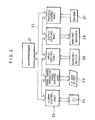
- 238000010586 diagram Methods 0.000 description 10
- 230000006870 function Effects 0.000 description 10
- 238000005192 partition Methods 0.000 description 9
- 238000009434 installation Methods 0.000 description 8
- 238000010168 coupling process Methods 0.000 description 6
- 238000005859 coupling reaction Methods 0.000 description 6
- 238000004804 winding Methods 0.000 description 6
- 230000037431 insertion Effects 0.000 description 5
- 229910052751 metal Inorganic materials 0.000 description 5
- 239000002184 metal Substances 0.000 description 5
- 230000000694 effects Effects 0.000 description 4
- 230000008569 process Effects 0.000 description 4
- 230000008878 coupling Effects 0.000 description 3
- 239000003599 detergent Substances 0.000 description 3
- 238000004519 manufacturing process Methods 0.000 description 3
- 229920006267 polyester film Polymers 0.000 description 3
- 241001269238 Data Species 0.000 description 2
- 229910000831 Steel Inorganic materials 0.000 description 2
- 229910052782 aluminium Inorganic materials 0.000 description 2
- XAGFODPZIPBFFR-UHFFFAOYSA-N aluminium Chemical compound [Al] XAGFODPZIPBFFR-UHFFFAOYSA-N 0.000 description 2
- 238000004140 cleaning Methods 0.000 description 2
- 230000002401 inhibitory effect Effects 0.000 description 2
- 239000000463 material Substances 0.000 description 2
- 239000011295 pitch Substances 0.000 description 2
- 230000001105 regulatory effect Effects 0.000 description 2
- 230000035939 shock Effects 0.000 description 2
- 239000010959 steel Substances 0.000 description 2
- 240000006829 Ficus sundaica Species 0.000 description 1
- 238000005452 bending Methods 0.000 description 1
- 230000003139 buffering effect Effects 0.000 description 1
- 239000013078 crystal Substances 0.000 description 1
- 230000007547 defect Effects 0.000 description 1
- 230000000994 depressogenic effect Effects 0.000 description 1
- 239000013013 elastic material Substances 0.000 description 1
- 230000000415 inactivating effect Effects 0.000 description 1
- 230000002779 inactivation Effects 0.000 description 1
- 238000012423 maintenance Methods 0.000 description 1
- 238000007645 offset printing Methods 0.000 description 1
- 230000000149 penetrating effect Effects 0.000 description 1
- 229910052705 radium Inorganic materials 0.000 description 1
- HCWPIIXVSYCSAN-UHFFFAOYSA-N radium atom Chemical compound [Ra] HCWPIIXVSYCSAN-UHFFFAOYSA-N 0.000 description 1
- 239000011347 resin Substances 0.000 description 1
- 229920005989 resin Polymers 0.000 description 1
- 238000000926 separation method Methods 0.000 description 1
- 239000002689 soil Substances 0.000 description 1
Images


Classifications
-
- B—PERFORMING OPERATIONS; TRANSPORTING
- B41—PRINTING; LINING MACHINES; TYPEWRITERS; STAMPS
- B41L—APPARATUS OR DEVICES FOR MANIFOLDING, DUPLICATING OR PRINTING FOR OFFICE OR OTHER COMMERCIAL PURPOSES; ADDRESSING MACHINES OR LIKE SERIES-PRINTING MACHINES
- B41L29/00—Devices for attaching printing elements or formes to supports
- B41L29/12—Devices for attaching printing elements or formes to supports for attaching flexible printing formes
- B41L29/14—Clamping devices
- B41L29/16—Clamping devices operating automatically during operation of rotary machines to attach the printing formes to the forme cylinders
Definitions
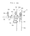
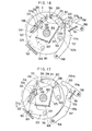
- a stopper pin 149 is set to the left-side board (not shown) for constraining the counterclockwise rotation of the lever 143.
- the lever 143 is rotated in the counterclockwise direction as shown in Fig. 6, and as a result, the drive lever 140 also rotates in the counterclockwise direction before eventually being set to the predetermined rotating position to activate operation of the operation lever 521 of the plate feeding/discharging unit 5.
- the driver lever 140 also rotates clockwise to return to the predetermined rotation position for relieving the operation lever 521 of the plate feeding/discharging unit 5 from the operative status.
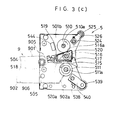
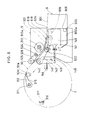
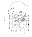
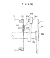
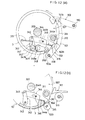
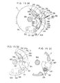
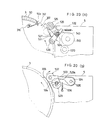
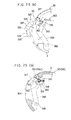
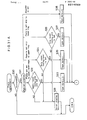
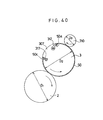
- the left-side board 101 of the printing press body 1 is provided with a plate feeding/discharging cam mechanism shown in Figs 10 and 11. Note that, to easily understand the constitution, illustration of the left-side board 101 is deleted from Fig. 11. The same applies to the ensuing drawings.
- the plate feeding/discharging cam mechanism is comprised of the following: A solenoid 150 is secured to the external surface of the left-side board 101. A shaft means 151 penetrating the left- teside board 101 is set so that it can freely rotate itself. A link 152 and a set-lever 153 are respectively secured to the external and internal edges of the shaft 151. A set-roller 154 is secured to the tip end of the set-lever 153.
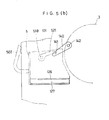
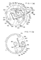
- the external surface of the left-side part of the plate cylinder 3 is provided with a plate-head clamping nail operation mechanism.
- This mechanism is comprised of the following:
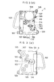
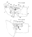
- the left-end of the nail shaft 311 shown in Fig. 10 (b) extends itself up to the outer portion of the left-side part of the plate cylinder 3 shown in Fig. 10 (a), while a link 321 is connected ot the extended portion of the nail shaft 311.
- Another link 322 is installed to a shaft 323 set to the left-side part of the plate cylinder 3 so that it can freely rotate.
- Rollers 320 and 324 are respectively installed to the center and tip-end positions of the link 322.
- a tension spring 325 is installed between the link 322 and the left-side part 310 to allow the link 322 to rotate counterclockwise pivoting the shaft 323. The counterclockwise rotation of the link 322 is constrained by engaging the roller 324 with the link 321.
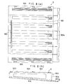
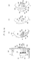
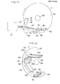
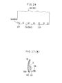
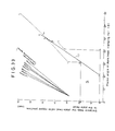
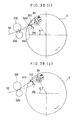
- the plate head 50c should reach the position (point "e") at which the plate-head clamping nails 312 completes its closing operation after passing through the area S surrounded by the lines - a - b - c - d - k - j - i - h - g - a.
- the plate-head track denoted by straight line “e” through “f” represents the condition in which the clamped plate 50 is tightly pulled.
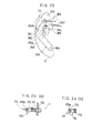
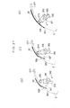
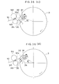
- Fig. 36 (d) denotes the state in which the phase angle ⁇ is at 30.2 while gradually accelerating the moving speed of the printing plate 50 itself and the tip end of the plate-head clamping nails 312 is exactly at the line extended from the track of the printing plate 50.
- Fig. 36 (e) denotes the state in which the tip end of the plate-head clamping nails 312 passes through the track-extended line of the printing plate 50 when the phase angle ⁇ is 30.5°, thus enabling the plate head 50a to proceed into the space 368 at a still further accelerated speed.
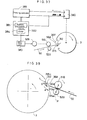
- this preferred embodiment introduces the following constitution, in which the diameter D 1 is determined to be 153.2 mm and D 3 to be 60.5 mm against 153.2 mm of the diameter D 2 , thus providing slightly larger diameters.
- This provides the blanket cylinder 2 and the form roller 710 with reasonable circumferential speeds which are slightly faster than that of the plate cylinder 3.
- These diameters denote one of the preferred embodiments of the present invention, and thus, any diameter other than those which are shown above may freely be chosen.
Landscapes
- Supply, Installation And Extraction Of Printed Sheets Or Plates (AREA)
Applications Claiming Priority (2)
| Application Number | Priority Date | Filing Date | Title |
|---|---|---|---|
| JP203611/85 | 1985-09-13 | ||
| JP60203611A JPH0669749B2 (ja) | 1985-09-13 | 1985-09-13 | 印刷機における版装着方法 |
Publications (3)
| Publication Number | Publication Date |
|---|---|
| EP0214549A2 true EP0214549A2 (de) | 1987-03-18 |
| EP0214549A3 EP0214549A3 (en) | 1988-08-24 |
| EP0214549B1 EP0214549B1 (de) | 1991-10-09 |
Family
ID=16476907
Family Applications (1)
| Application Number | Title | Priority Date | Filing Date |
|---|---|---|---|
| EP86111829A Expired EP0214549B1 (de) | 1985-09-13 | 1986-08-27 | Druckmaschine und Verfahren zum Zuführen einer Druckplatte |
Country Status (4)
| Country | Link |
|---|---|
| US (1) | US4858528A (de) |
| EP (1) | EP0214549B1 (de) |
| JP (1) | JPH0669749B2 (de) |
| DE (1) | DE3681860D1 (de) |
Cited By (4)
| Publication number | Priority date | Publication date | Assignee | Title |
|---|---|---|---|---|
| US7156022B2 (en) | 2003-03-28 | 2007-01-02 | Koenig & Bauer Aktiengesellschaft | Method for supplying dressings to a cylinder of a printing machine |
| US7159516B2 (en) | 2003-03-28 | 2007-01-09 | Koenig & Bauer Aktiengesellschaft | Devices for storing a dressing to be supplied to a cylinder of a printing machine |
| RU2304516C2 (ru) * | 2003-03-28 | 2007-08-20 | Кениг Унд Бауер Акциенгезельшафт | Устройство для накопления декелей, предназначенных для подачи на цилиндр печатной машины |
| US7331287B2 (en) | 2003-03-28 | 2008-02-19 | Koenig & Bauer Aktiengesellschaft | Devices for storing a blanket to be exchanged on a cylinder of a printing machine |
Families Citing this family (27)
| Publication number | Priority date | Publication date | Assignee | Title |
|---|---|---|---|---|
| JPH0788091B2 (ja) * | 1986-11-20 | 1995-09-27 | 三菱重工業株式会社 | 枚葉オフセット印刷機の自動版交換制御装置 |
| ATE120129T1 (de) * | 1989-12-06 | 1995-04-15 | Komori Printing Mach | Apparat zum wechseln von druckplatten für druckpresse. |
| DE3940796A1 (de) * | 1989-12-09 | 1991-06-13 | Koenig & Bauer Ag | Verfahren und einrichtung zum automatischen wechseln einer druckplatte |
| DE3940795A1 (de) * | 1989-12-09 | 1991-06-13 | Koenig & Bauer Ag | Verfahren und einrichtung zum automatischen zufuehren bzw. abfuehren einer druckplatte |
| US5132911A (en) * | 1989-12-27 | 1992-07-21 | Leader Engineering Fabrication, Inc. | Apparatus for mounting and proofing printing plates |
| JPH0526374U (ja) * | 1991-09-19 | 1993-04-06 | アキヤマ印刷機製造株式会社 | 印刷機の刷版案内装置 |
| JP2585989Y2 (ja) * | 1991-12-11 | 1998-11-25 | 株式会社小森コーポレーション | 版胴への刷版装着装置 |
| USD351188S (en) | 1992-06-19 | 1994-10-04 | Ryobi Ltd. | Offset printing machine |
| USD350561S (en) | 1992-06-19 | 1994-09-13 | Ryobi Ltd. | Offset printing machine |
| DE4331430A1 (de) * | 1992-09-18 | 1994-03-24 | Koenig & Bauer Ag | Einrichtung zum Zu- und Abführen von Druckplatten |
| DE4394496D2 (de) * | 1992-09-18 | 1995-09-21 | Koenig & Bauer Ag | Verfahren zum Zuführen von Druckplatten |
| GB9301570D0 (en) * | 1993-01-27 | 1993-03-17 | Lin Pac Containers Int | Printing cylinder assembly |
| DE4440239C5 (de) * | 1994-11-10 | 2007-11-22 | Man Roland Druckmaschinen Ag | Wälzelement zum Andrücken einer flexiblen Druckplatte an den Formzylinder |
| DE19614818A1 (de) * | 1996-04-15 | 1997-10-16 | Wifag Maschf | Drehgeber für einen Zylinder einer Druckmaschine |
| US6113346A (en) | 1996-07-31 | 2000-09-05 | Agfa Corporation | Method for loading and unloading a supply of plates in an automated plate handler |
| DE10248689A1 (de) * | 2001-11-16 | 2003-05-28 | Heidelberger Druckmasch Ag | Verfahren zum automatischen Wechseln einer Druckplatte sowie entsprechende Rotationsdruckmaschine |
| DE10314343B4 (de) | 2003-03-28 | 2009-08-13 | Koenig & Bauer Aktiengesellschaft | Vorrichtung zum Speichern eines an einem Zylinder einer Druckmaschine auszutauschenden Aufzugs |
| GB2413530A (en) * | 2004-04-29 | 2005-11-02 | Goss Graphic Systems Ltd | Printing plate module and printing press |
| US8051774B2 (en) * | 2004-04-29 | 2011-11-08 | Goss Graphic Systems Limited | Printing plate module, printing press, and method of mounting plates |
| JP4426387B2 (ja) * | 2004-06-25 | 2010-03-03 | リョービ株式会社 | 印刷機 |
| GB2425987A (en) * | 2005-05-09 | 2006-11-15 | Goss Graphic Systems Ltd | Printing plate unloading apparatus and method |
| GB2428634B (en) * | 2005-08-04 | 2008-09-17 | Goss Graphic Systems Ltd | Printing press |
| DE102005039773B4 (de) | 2005-08-22 | 2011-12-01 | Koenig & Bauer Aktiengesellschaft | Vorrichtung zum Zuführen oder Abführen eines Aufzugs mit einfacher oder doppelter Länge zu oder von einem Zylinder einer Druckmaschine |
| DE102006006136A1 (de) | 2006-02-10 | 2007-08-23 | Koenig & Bauer Aktiengesellschaft | Systeme zur Überprüfung der Bestückung eines Druckformmagazins und ein System zur Zuführung mindestens einer in einem Druckformmagazin gespeicherten Druckform zu einem Zylinder |
| WO2008028309A1 (de) * | 2006-09-03 | 2008-03-13 | Gietz Ag | Registereinzugsvorrichtung |
| US8950325B2 (en) * | 2010-08-12 | 2015-02-10 | Goss International Corporation | Press inking system with key sharing provision |
| CN109203673B (zh) * | 2018-08-29 | 2023-09-15 | 滁州千字文印务有限公司 | 一种用于四色印刷机的气动力调节及预警装置 |
Citations (1)
| Publication number | Priority date | Publication date | Assignee | Title |
|---|---|---|---|---|
| US3719142A (en) | 1971-11-24 | 1973-03-06 | Ricoh Kk | Automatic plate clamping and discharging device for use in offset printing press |
Family Cites Families (9)
| Publication number | Priority date | Publication date | Assignee | Title |
|---|---|---|---|---|
| US3451336A (en) * | 1966-01-13 | 1969-06-24 | Addressograph Multigraph | Master making and duplicating machine |
| US3871294A (en) * | 1968-12-30 | 1975-03-18 | Ricoh Kk | Duplicator master feed using decimal code to set copy count |
| US3858508A (en) * | 1969-09-15 | 1975-01-07 | Ricoh Kk | Offset printing machine |
| JPS5513912B2 (de) * | 1972-07-24 | 1980-04-12 | ||
| DE2642580C3 (de) * | 1976-09-22 | 1979-03-15 | Mathias Baeuerle Gmbh, 7742 St Georgen | Farbwerk einer Klein-Rotationsdruckmaschine |
| JPS5557489A (en) * | 1978-10-26 | 1980-04-28 | Toray Ind Inc | Type printing method and printer |
| JPS5652046U (de) * | 1979-09-25 | 1981-05-08 | ||
| JPS57105353A (en) * | 1980-12-24 | 1982-06-30 | Ricoh Co Ltd | Plate ejecting device of printing machine |
| US4459913A (en) * | 1982-08-17 | 1984-07-17 | A. B. Dick Company | Adjustment structure for master holder |
-
1985
- 1985-09-13 JP JP60203611A patent/JPH0669749B2/ja not_active Expired - Fee Related
-
1986
- 1986-08-27 DE DE8686111829T patent/DE3681860D1/de not_active Expired - Fee Related
- 1986-08-27 EP EP86111829A patent/EP0214549B1/de not_active Expired
- 1986-08-28 US US06/902,423 patent/US4858528A/en not_active Expired - Lifetime
Patent Citations (1)
| Publication number | Priority date | Publication date | Assignee | Title |
|---|---|---|---|---|
| US3719142A (en) | 1971-11-24 | 1973-03-06 | Ricoh Kk | Automatic plate clamping and discharging device for use in offset printing press |
Cited By (4)
| Publication number | Priority date | Publication date | Assignee | Title |
|---|---|---|---|---|
| US7156022B2 (en) | 2003-03-28 | 2007-01-02 | Koenig & Bauer Aktiengesellschaft | Method for supplying dressings to a cylinder of a printing machine |
| US7159516B2 (en) | 2003-03-28 | 2007-01-09 | Koenig & Bauer Aktiengesellschaft | Devices for storing a dressing to be supplied to a cylinder of a printing machine |
| RU2304516C2 (ru) * | 2003-03-28 | 2007-08-20 | Кениг Унд Бауер Акциенгезельшафт | Устройство для накопления декелей, предназначенных для подачи на цилиндр печатной машины |
| US7331287B2 (en) | 2003-03-28 | 2008-02-19 | Koenig & Bauer Aktiengesellschaft | Devices for storing a blanket to be exchanged on a cylinder of a printing machine |
Also Published As
| Publication number | Publication date |
|---|---|
| US4858528A (en) | 1989-08-22 |
| JPH0669749B2 (ja) | 1994-09-07 |
| EP0214549A3 (en) | 1988-08-24 |
| EP0214549B1 (de) | 1991-10-09 |
| JPS6262758A (ja) | 1987-03-19 |
| DE3681860D1 (de) | 1991-11-14 |
Similar Documents
| Publication | Publication Date | Title |
|---|---|---|
| EP0214549A2 (de) | Druckmaschine und Verfahren zum Zuführen einer Druckplatte | |
| EP0213597B1 (de) | Mehrfarbendruckmaschine | |
| US6135446A (en) | Aligning device | |
| US5333547A (en) | Gripper apparatus on sheet-processing machines | |
| JP2576854Y2 (ja) | 枚葉印刷機の排紙装置 | |
| US4971311A (en) | Feeder for sheet-feed printing machine | |
| JPH0549569B2 (de) | ||
| US4863085A (en) | Apparatus for transporting a strip of photographic printing paper in a printer | |
| US5107296A (en) | Photographic paper transporting apparatus and method for photographic printer | |
| US5390603A (en) | Method for automatic changing of printing plates | |
| US20060120781A1 (en) | Registration device, image forming apparatus having the same, and aligning method therefor | |
| JPH05138849A (ja) | 枚葉紙オフセツト印刷機械の紙差しゲージ付近の用紙移動を監視するための装置 | |
| US5253583A (en) | Device for positioning printing material for use in a printing apparatus | |
| US4767113A (en) | Sheet film feeder | |
| JPS6262756A (ja) | 印刷機 | |
| JPS6262759A (ja) | 印刷機における自動給排版方法 | |
| JPH0336667B2 (de) | ||
| CA1039105A (en) | Offset duplicator with master treating means | |
| JPS62199476A (ja) | 紙搬送装置 | |
| JPH0586356B2 (de) | ||
| JPS6262753A (ja) | 印刷機における版尻つかみ装置 | |
| JPS6246843A (ja) | 給紙装置 | |
| JPH0336666B2 (de) | ||
| JP2780288B2 (ja) | サーマルプリンタ装置 | |
| JPS584628B2 (ja) | 印刷機におけるマスタクランプの制御装置 |
Legal Events
| Date | Code | Title | Description |
|---|---|---|---|
| PUAI | Public reference made under article 153(3) epc to a published international application that has entered the european phase |
Free format text: ORIGINAL CODE: 0009012 |
|
| AK | Designated contracting states |
Kind code of ref document: A2 Designated state(s): CH DE FR GB LI |
|
| PUAL | Search report despatched |
Free format text: ORIGINAL CODE: 0009013 |
|
| AK | Designated contracting states |
Kind code of ref document: A3 Designated state(s): CH DE FR GB LI |
|
| 17P | Request for examination filed |
Effective date: 19880930 |
|
| 17Q | First examination report despatched |
Effective date: 19900309 |
|
| GRAA | (expected) grant |
Free format text: ORIGINAL CODE: 0009210 |
|
| AK | Designated contracting states |
Kind code of ref document: B1 Designated state(s): CH DE FR GB LI |
|
| REF | Corresponds to: |
Ref document number: 3681860 Country of ref document: DE Date of ref document: 19911114 |
|
| ET | Fr: translation filed | ||
| PLBE | No opposition filed within time limit |
Free format text: ORIGINAL CODE: 0009261 |
|
| STAA | Information on the status of an ep patent application or granted ep patent |
Free format text: STATUS: NO OPPOSITION FILED WITHIN TIME LIMIT |
|
| 26N | No opposition filed | ||
| REG | Reference to a national code |
Ref country code: GB Ref legal event code: IF02 |
|
| PGFP | Annual fee paid to national office [announced via postgrant information from national office to epo] |
Ref country code: FR Payment date: 20020808 Year of fee payment: 17 |
|
| PGFP | Annual fee paid to national office [announced via postgrant information from national office to epo] |
Ref country code: GB Payment date: 20020821 Year of fee payment: 17 |
|
| PGFP | Annual fee paid to national office [announced via postgrant information from national office to epo] |
Ref country code: CH Payment date: 20020831 Year of fee payment: 17 |
|
| PGFP | Annual fee paid to national office [announced via postgrant information from national office to epo] |
Ref country code: DE Payment date: 20020904 Year of fee payment: 17 |
|
| PG25 | Lapsed in a contracting state [announced via postgrant information from national office to epo] |
Ref country code: GB Free format text: LAPSE BECAUSE OF NON-PAYMENT OF DUE FEES Effective date: 20030827 |
|
| PG25 | Lapsed in a contracting state [announced via postgrant information from national office to epo] |
Ref country code: LI Free format text: LAPSE BECAUSE OF NON-PAYMENT OF DUE FEES Effective date: 20030831 Ref country code: CH Free format text: LAPSE BECAUSE OF NON-PAYMENT OF DUE FEES Effective date: 20030831 |
|
| PG25 | Lapsed in a contracting state [announced via postgrant information from national office to epo] |
Ref country code: DE Free format text: LAPSE BECAUSE OF NON-PAYMENT OF DUE FEES Effective date: 20040302 |
|
| REG | Reference to a national code |
Ref country code: CH Ref legal event code: PL |
|
| GBPC | Gb: european patent ceased through non-payment of renewal fee | ||
| PG25 | Lapsed in a contracting state [announced via postgrant information from national office to epo] |
Ref country code: FR Free format text: LAPSE BECAUSE OF NON-PAYMENT OF DUE FEES Effective date: 20040430 |
|
| REG | Reference to a national code |
Ref country code: FR Ref legal event code: ST |