EP0214428A2 - Method and carding machine for producing a fibrous web - Google Patents
Method and carding machine for producing a fibrous web Download PDFInfo
- Publication number
- EP0214428A2 EP0214428A2 EP86110149A EP86110149A EP0214428A2 EP 0214428 A2 EP0214428 A2 EP 0214428A2 EP 86110149 A EP86110149 A EP 86110149A EP 86110149 A EP86110149 A EP 86110149A EP 0214428 A2 EP0214428 A2 EP 0214428A2
- Authority
- EP
- European Patent Office
- Prior art keywords
- working
- drum
- drums
- roller
- working drum
- Prior art date
- Legal status (The legal status is an assumption and is not a legal conclusion. Google has not performed a legal analysis and makes no representation as to the accuracy of the status listed.)
- Granted
Links
Images

Classifications
-
- D—TEXTILES; PAPER
- D01—NATURAL OR MAN-MADE THREADS OR FIBRES; SPINNING
- D01G—PRELIMINARY TREATMENT OF FIBRES, e.g. FOR SPINNING
- D01G15/00—Carding machines or accessories; Card clothing; Burr-crushing or removing arrangements associated with carding or other preliminary-treatment machines
- D01G15/02—Carding machines
Definitions
- the invention relates to a method for producing nonwoven from fiber material by means of a card or the like, in which the fiber material is carded using at least two working drums of the same diameter running in the same direction, and to a card for producing nonwoven from fiber material, with at least one feed roller or the like.
- the fiber material is carded using at least two working drums of the same diameter running in the same direction
- a card for producing nonwoven from fiber material with at least one feed roller or the like.
- the worker turner rolls which have a smaller diameter than the main or random roll (s) in the generic device in the usual way, serve the purpose of ensuring sufficient carding of the fiber material, while the random roll (s) serve the purpose pursues, or pursue, to achieve the greatest possible uniformity of the nonwoven structure over the entire width of the nonwoven to be manufactured, in accordance with the general goal of keeping the ratio of longitudinal to transverse strength as far as possible in the range of 1: 1 over the entire extent of the nonwoven.
- the invention has for its object to provide a method and a card of the generic type, which enables the achievement of higher working widths with reduced design effort at high working speeds while ensuring the greatest possible uniformity of the random nonwoven structure over the entire width of the nonwoven.
- this object is achieved in a method of the type mentioned at the outset in that the fiber material is guided with adjustable partial restoration over at least three mutually adjustable working drums.
- a preferred embodiment of the method according to the invention provides that the working drums are driven independently of one another at an adjustable speed.
- the card of the generic type according to the invention is characterized in order to achieve the above-mentioned object in that two working drums (each) cooperate with the roughing roller and / or one of the first working drums directly downstream of it, which together are followed by a further working drum.
- a second work drum and a third work drum interact with the first work drum immediately downstream of the pre-roll, which are jointly followed by a fourth work drum.
- first working drum and a second working drum can also be made for the first working drum and a second working drum to be engaged with the roughing roller, the first and second working drums and possibly a third working drum interacting with the first working drum cooperating with a fourth working drum.
- the invention further provides that the first working drum and the second working drum are in line with one another.
- the fourth working drum is followed by a fifth and a sixth working drum which are followed or followed by at least one further working drum and / or the take-off roller (s).
- the device according to the invention may also be characterized in that at least one of the working drums interacts with three other working drums.
- At least one of the working drums interacts with four other working drums.
- the invention also provides that the relative speeds and / or the mutual spacing of the working drums for controlling the proportion of the fiber material that can be restored to the respective working drum on the one hand and the fiber material that can be transferred to the respective downstream working drum on the other hand are adjustable.
- Another embodiment of the invention proposes that the working drums are provided with saw tooth sets or the like.
- the pre-roller running in the same direction with the feed roller which can optionally be connected upstream of a feed trough in a known manner, also runs in the same direction with the work drums, but the pre-roller and work drums can also rotate in opposite directions with one another.
- the invention is based on the surprising finding that it is possible to achieve the object in a simple manner by completely satisfying the carding action, completely dispensing with the worker turner rolls previously regarded as indispensable and to achieve uniformity of the nonwoven to be produced over the entire width of the nonwoven, even with the largest possible machine widths, if a number of working drums of the same diameter are provided which interact in the manner claimed.
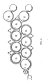
- the card according to the invention has, in the exemplary embodiment shown there, a feed roller 10 which, as in the generic card, can optionally interact with a feed trough or the like; Of course, several feed rollers or troughs can also be provided.
- the feed roller 10, for example, at a speed of 10 m / min. can run, applied in the same direction a preliminary roller 12, the rotational speed of which, for example, at about 300 m / min. can lie.
- the roughing roller 12 which therefore runs in the same direction as the feed roller 10 and the surface of which is like that of the feed roller 10 and also, in the exemplary embodiment shown, is provided with an appropriately designed saw tooth set for all downstream rollers or drums, is a counter-rotating first working drum 14 downstream, which in turn interacts with a second working drum 16 and a third working drum 18.
- the second working drum 16 and the third working drum 18 act on a fourth working drum 20, which in turn is followed by a fifth working drum 22 and a sixth working drum 24, the fifth working drum 22 and the sixth working drum 24 in turn being followed by a seventh working drum 25.
- the working drums 14, 16, 18, 20, 22, 24 and 25 each have a rotational speed of, for example, approx. 1400 m / min.
- the relative speeds of the working drums, however, as well as their relative spacing, ie the width of the respective roll gaps, can be set .
- the work drums 14, 16, 18, 20, 22, 24, 25 are followed in the manner shown in the drawing by two take-off rollers 26, 27 which run in the opposite direction to all work drums running in the same direction at a peripheral speed of, for example, approximately 116 m / min. to run.
- the feed roller 10 conveys fiber material in a known manner to the pre-roller 12 in a uniform manner.
- the first working drum 14 which runs in the opposite direction to this with considerable delay, as shown, removes the fiber material and cards it in a first step in cooperation with the second Working drum 16 and the third working drum 18.
- not all of the fiber material taken over by the first working drum 14 from the roughing roll 12 is immediately applied to the second working drum 16 or the third working drum 18 transferred, rather only that existing in a transmission area 28, as can be seen from the drawing, while the portion of the fiber material present in a storage area 30 is returned one or more times and subjected to further carding.
- the take-off roller 26 in its place, of course, a multiple roller take-off or the like could also be provided in a known manner, as is also provided in the generic device, possibly also connected to an upset roller take-off described there, runs considerably slower than the working drums, so that a relatively strongly "pushed together" fleece is pushed onto it.
- the nonwoven material obtained is uniform over the entire working width of the machine and has a ratio of longitudinal to transverse strength of approximately 1: 1, as is desired.
- the working drums of the same diameter can be produced without bending even with very large working widths of the machine. In addition to eliminating the problem of roll deflection, the absence of worker and turner rolls ensures a considerably simpler construction.
- two working drums 14, 16 cooperate with the roughing roller 12, which are followed by further working drums 18, 20, 22, 24 and 25 in the manner shown in the drawing, all of which are assigned to one another in such a way that the fiber material brought in by means of the feed roller 10 is further transferred or stored back to the desired extent by the individual working drums, the front roller 12 of course not being involved in the storage.
- the speeds of rotation of the feed roller 10, the front roller 12 running in the same direction as well as the working drums 12, 14, 16, 20, 22, 24 and 25 running in the opposite direction as well as the take-off rollers 26, 27 are correct with the values given in connection with FIG match. Otherwise, the device operates in the manner explained above with reference to the exemplary embodiment in FIG. 1.
Abstract
Description
Die Erfindung betrifft ein Verfahren zur Vliesherstellung aus Fasermaterial mittels einer Krempel oder dgl., bei dem das Fasermaterial unter Verwendung wenigstens zweier gleichsinnig miteinander laufender Arbeitstrommeln gleichen Durchmessers kardiert wird, sowie eine Krempel zur Vliesherstellung aus Fasermaterial, mit mindestens einer Einzugswalze od.dgl., einer hierzu gleichsinnig mit einem Verzug zwischen 100 und 200 laufenden Vorwalze, mindestens zwei der Vorwalze nachgeordneten, gleichsinnig miteinander laufenden Arbeitstrommeln gleichen Durchmessers, deren Drehzahl größer ist als die der Vorwalze, sowie wenigstens einer der wirkungsmäßig am weitesten von der Vorderwalze entfernten Arbeitstrommeln zugeordneten Abnehmerwalze, insbesondere zur Durchführung des vorgenannten Verfahrens.The invention relates to a method for producing nonwoven from fiber material by means of a card or the like, in which the fiber material is carded using at least two working drums of the same diameter running in the same direction, and to a card for producing nonwoven from fiber material, with at least one feed roller or the like. one in the same direction with a delay between 100 and 200 running pre-roller, at least two downstream of the pre-roller, in the same direction with each other running work drums of the same diameter, the speed of which is greater than that of the front roller, and at least one of the pickup rollers which are functionally most distant from the front roller, in particular for carrying out the aforementioned method.
Aus der DE-GM 82 18 526 sind ein Verfahren sowie eine Krempel der vorstehend beschriebenen Art bekannt, bei denen die der Vorwalze nachgeordneten Arbeitstrommeln als Hauptwalzen ausgebildet sind, denen jeweils eine Wirrwalze nachgeordnet und ferner, wie dies bei Krempeln der hier in Rede stehenden Art allgemein üblich ist, jeweils mindestens ein Paar von Arbeiter- und Wenderwalzen zugeordnet ist. Die Arbeiterwenderwalzen, die bei der gattungsgemäßen Vorrichtung in allgemein üblicher Art einen kleineren Durchmesser als die Haupt- bzw. Wirrwalze(n) aufweisen, dienen dabei dem Zweck, für eine ausreichende Kardierung des Fasermaterials Sorge zu tragen, während die Wirrwalze(n) den Zweck verfolgt bzw. verfolgen, über die gesamte Breite des herzustellenden Vlieses eine möglichst große Gleichmäßigkeit der Wirrvliesstruktur zu erreichen, in Übereinstimmung mit dem allgemein angestrebten Ziel, über die gesamte Vlieserstreckung des Verhältnis von Längs- zu Querfestigkeit möglichst im Bereich von 1 : 1 zu halten.From DE-GM 82 18 526 a method and a card of the type described above are known, in which the downstream work drums are designed as main rollers, each of which is arranged downstream of a random roller and further, as is the case with cards of the type in question is common practice, at least one pair of worker and turning rollers is assigned. The worker turner rolls, which have a smaller diameter than the main or random roll (s) in the generic device in the usual way, serve the purpose of ensuring sufficient carding of the fiber material, while the random roll (s) serve the purpose pursues, or pursue, to achieve the greatest possible uniformity of the nonwoven structure over the entire width of the nonwoven to be manufactured, in accordance with the general goal of keeping the ratio of longitudinal to transverse strength as far as possible in the range of 1: 1 over the entire extent of the nonwoven.
Aus der DE-PS 23 43 064 ist eine Krempel bekannt, bei der anders als bei der gattungsgemäßen Vorrichtung die jeweils aufeinanderfolgenden Arbeitstrommeln gegensinnig laufen, wobei ebenfalls Arbeiterwenderwalzen der bereits beschriebenen Art, die geringeren Durchmesser als die Arbeitstrommeln haben, vorgesehen sind. Dabei ist es nachteilig, daß die einzelnen Arbeits trommeln jeweils steigende Drehzahl aufweisen müssen, so daß der erzielbare Kardiereffekt bzw. die Anzahl der möglichen, hintereinander angeordneten Arbeitstrommeln naturgemäß begrenzt ist, da sich natürlich beliebig hohe Drehzahlen nicht realisieren lassen.From DE-PS 23 43 064 a card is known in which, in contrast to the device of the generic type, the successive work drums run in opposite directions, whereby worker turner rolls of the type already described, which have a smaller diameter than the work drums, are also provided. It is disadvantageous that the individual work drums must each have increasing speed, so that the achievable carding effect or the number of possible working drums arranged one behind the other is naturally limited, since naturally high speeds cannot be realized.
Das gattungsgemäße Verfahren hat sich ebenso wie die diesbezügliche Krempel im Prinzip durchaus bewährt. Es hat sich aber gezeigt, daß infolge der allgemein beobachteten Tendenz, die Arbeitsbreite derartiger Krempel immer mehr zu steigern, die Verwendung der Arbeiter- und Wenderwalzen mit notwendigerweise verhältnismäßig geringem Durchmesser, verglichen mit den Hauptwalzen, immer stärkere Schwierigkeiten mit sich bringt, da beispielsweise bei Arbeitsbreiten von 4 m oder mehr Durchbiegungen der betreffenden Walzen unvermeidbar sind. Außerdem ist der konstruktive Aufwand infolge der erforderlichen zahlreichen unterschiedlichen Umfangsgeschwindigkeiten der Walzen verschiedenen Durchmessers, wie Hauptwalzen, Wirrwalzen sowie Arbeiter- und Wenderwalzen, verhältnismäßig aufwendig.The generic method, like the related card, has proven itself in principle. However, it has been shown that, as a result of the generally observed tendency to increase the working width of such cards more and more, the use of the worker and turner rolls, which are necessarily of relatively small diameter compared to the main rolls, poses ever greater difficulties, for example with Working widths of 4 m or more deflections of the rollers in question are unavoidable. In addition, the design effort is relatively complex due to the required numerous different peripheral speeds of the rolls of different diameters, such as main rolls, random rolls and worker and turner rolls.
Der Erfindung liegt die Aufgabe zugrunde, ein Verfahren sowie eine Krempel der gattungsgemäßen Art zu schaffen, welche bei verringertem konstruktiven Aufwand bei hohen Arbeitsgeschwindigkeiten die Erzielung höherer Arbeitsbreiten bei Gewährleistung einer weitestgehenden Gleichmäßigkeit der Wirrvliesstruktur über die gesamte Vliesbreite ermöglicht.The invention has for its object to provide a method and a card of the generic type, which enables the achievement of higher working widths with reduced design effort at high working speeds while ensuring the greatest possible uniformity of the random nonwoven structure over the entire width of the nonwoven.
Erfindungsgemäß wird diese Aufgabe bei einem Verfahren der eingangs genannten Art dadurch gelöst, daß das Fasermaterial unter einstellbarer teilweiser Rückspeicherung über mindestens drei miteinander in gegenseitigem einstellbaren Eingriff stehende Arbeitstrommeln geführt wird.According to the invention, this object is achieved in a method of the type mentioned at the outset in that the fiber material is guided with adjustable partial restoration over at least three mutually adjustable working drums.
Eine bevorzugte Ausführungsform des Verfahrens nach der Erfindung sieht vor, daß die Arbeitstrommeln unabhängig voneinander mit einstellbarer Drehzahl angetrieben werden.A preferred embodiment of the method according to the invention provides that the working drums are driven independently of one another at an adjustable speed.
Die erfindungsgemäße Krempel der gattungsgemäßen Art ist zur Lösung der oben angegebenen Aufgabe dadurch gekennzeichnet, daß mit der Vorwalze und/oder einer dieser unmittelbar nachgeordneten ersten Arbeitstrommel (jeweils) zwei Arbeitstrommeln zusammenwirken, denen gemeinsam eine weitere Arbeitstrommel nachgeschaltet ist.The card of the generic type according to the invention is characterized in order to achieve the above-mentioned object in that two working drums (each) cooperate with the roughing roller and / or one of the first working drums directly downstream of it, which together are followed by a further working drum.
Dabei kann vorgesehen sein, daß mit der der Vorwalze unmittelbar nachgeordneten ersten Arbeitstrommel eine zweite Arbeitstrommel und eine dritte Arbeitstrommel zusammenwirken, denen gemeinsam eine vierte Arbeitstrommel nachgeschaltet ist.It can be provided that a second work drum and a third work drum interact with the first work drum immediately downstream of the pre-roll, which are jointly followed by a fourth work drum.
Alternativ hierzu kann auch vorgesehen sein, daß mit der Vorwalze die erste Arbeitstrommel sowie eine zweite Arbeitstrommel in Eingriff stehen, wobei die erste und die zweite Arbeitstrommel sowie ggf. eine dritte, mit der ersten Arbeitstrommel zusammenwirkende Arbeitstrommel gemeinsam mit einer vierten Arbeitstrommel zusammenwirken.As an alternative to this, provision can also be made for the first working drum and a second working drum to be engaged with the roughing roller, the first and second working drums and possibly a third working drum interacting with the first working drum cooperating with a fourth working drum.
Die Erfindung sieht weiter ggf. vor, daß die erste Arbeitstrommel und die zweite Arbeitstrommel miteinander in Einklang stehen.The invention further provides that the first working drum and the second working drum are in line with one another.
Auch kann erfindungsgemäß vorgesehen sein, daß der vierten Arbeitstrommel eine fünfte und eine sechste Arbeitstrommel nachgeschaltet sind, denen mindestens eine weitere Arbeitstrommel und/oder die Abnehmerwalze(n) folgt bzw. folgen.It can also be provided according to the invention that the fourth working drum is followed by a fifth and a sixth working drum which are followed or followed by at least one further working drum and / or the take-off roller (s).
Die erfindungsgemäße Vorrichtung zeichnet sich weiter ggf. dadurch aus, daß mindestens eine der Arbeitstrommeln mit jeweils drei anderen Arbeitstrommeln zusammenwirkt.The device according to the invention may also be characterized in that at least one of the working drums interacts with three other working drums.
Dabei kann vorgesehen sein, daß mindestens eine der Arbeitstrommeln mit jeweils vier anderen Arbeitstrommeln zusammenwirkt.It can be provided that at least one of the working drums interacts with four other working drums.
Die Erfindung sieht weiterhin ggf. vor, daß die Relativgeschwindigkeiten und/oder die gegenseitigen Abstände der Arbeitstrommeln zur Steuerung des Anteils des auf der jeweiligen Arbeitstrommel rückspeicherbaren Fasermaterials einerseits sowie des auf die jeweils nachgeschaltete Arbeitstrommel übertragbaren Fasermaterials andererseits einstellbar sind.The invention also provides that the relative speeds and / or the mutual spacing of the working drums for controlling the proportion of the fiber material that can be restored to the respective working drum on the one hand and the fiber material that can be transferred to the respective downstream working drum on the other hand are adjustable.
Eine weitere Ausführungsform der Erfindung schlägt vor, daß die Arbeitstrommeln mit Sägezahngarnituren oder dergleichen versehen sind.Another embodiment of the invention proposes that the working drums are provided with saw tooth sets or the like.
Schließlich kann erfindungsgemäß vorgesehen sein, daß die Relativgeschwindigkeiten der Arbeitstrommeln das Dreifache der Umfangsgeschwindigkeit nicht übersteigen.Finally, it can be provided according to the invention that the relative speeds of the working drums do not exceed three times the peripheral speed.
Bei der erfindungsgemäßen Krempel kann vorgesehen sein, daß die mit der Einzugswalze, der in bekannter Weise ggf. eine Einzugsmulde vorgeschaltet sein kann, gleichsinnig laufende Vorwalze auch gleichsinnig mit den Arbeitstrommeln läuft, jedoch können Vorwalze und Arbeitstrommeln auch gegensinnig miteinander rotieren.In the card according to the invention it can be provided that the pre-roller running in the same direction with the feed roller, which can optionally be connected upstream of a feed trough in a known manner, also runs in the same direction with the work drums, but the pre-roller and work drums can also rotate in opposite directions with one another.
Der Erfindung liegt die überraschende Erkenntnis zugrunde, daß es gelingt, die gestellte Aufgabe auf einfache Weise dadurch zu lösen, daß unter völligem Verzicht auf die bislang als unerläßlich angesehenen Arbeiterwenderwalzen eine befriedigende Kardierwirkung und Gleichmäßigkeit des herzustellenden Vlieses über die gesamte Vliesbreite auch bei größtmöglichen Maschinenbreiten zu erzielen, wenn eine Anzahl von Arbeitstrommeln gleichen Durchmessers vorgesehen wird, die in der beanspruchten Art zusammenwirken. Hiermit läßt sich, verbunden mit der erfindungsgemäß vorgeschlagenen Einstellbarkeit der Relativgeschwindigkeiten sowie der Relativpositionen der einzelnen Arbeitstrommeln, bei entsprechender Gestaltung der Oberflächenstruktur, nämlich in Form von Sägezahngarnituren oder dergleichen, auf jeder einzelnen Arbeitstrommel eine steuerbare Rückspeichermöglichkeit schaffen, wobei also je nach Wunsch ein bestimmter Anteil des Fasermaterials auf der betreffenden Arbeitstrommel nochmals zurückgeführt und erneut der Kardierung unterworfen und der andere Anteil auf die nächstfolgende Arbeitstrommel übertragen wird. Natürlich können dabei nicht nur, wie erfindungsgemäß als Mindestanzahl vorgesehen, vier Arbeitstrommeln der beanspruchten Art zusammengeschaltet werden, sondern auch, wie dies Gegenstand einer vorstehend angegebenen bevorzugten Ausführungsform ist, dieser Vierergruppe von Arbeitstrommeln zwei weitere Arbeitstrommeln, aber gegebenenfalls auch weitere Vierergruppen sowie einzelne Arbeitstrommeln etc., nachgeschaltet werden, wobei allen Ausführungsformen gemeinsam ist, daß die Arbeitstrommeln jeweils gleichen Durchmesser haben und jeweils über einen eigenen Antrieb verfügen, wobei natürlich auch ein Zentralantrieb denkbar ist, solange nur gewährleistet ist, daß die einzelnen Arbeitstrommeln, in ihren gegenseitigen Relativpositionen verstellbar, jeweils mit steuerbarer Drehzahl unabhängig voneinander antriebbar sind.The invention is based on the surprising finding that it is possible to achieve the object in a simple manner by completely satisfying the carding action, completely dispensing with the worker turner rolls previously regarded as indispensable and to achieve uniformity of the nonwoven to be produced over the entire width of the nonwoven, even with the largest possible machine widths, if a number of working drums of the same diameter are provided which interact in the manner claimed. This, combined with the adjustability of the relative speeds and the relative positions of the individual work drums proposed according to the invention, with a corresponding design of the surface structure, namely in the form of sawtooth sets or the like, can create a controllable restoring possibility on each individual work drum, with a certain proportion as desired of the fiber material is returned to the relevant work drum and subjected to carding again and the other portion is transferred to the next work drum. Of course, not only can four work drums of the type claimed be interconnected, as provided according to the invention as a minimum number, but also, as is the subject of a preferred embodiment specified above, this group of four work drums two further work drums, but optionally also further groups of four and individual work drums etc. ., are connected downstream, with all of the embodiments having in common that the working drums each have the same diameter and each have their own drive, although of course a central drive is also conceivable as long as it is only ensured that the individual working drums are adjustable in their relative positions, can each be driven independently of one another at a controllable speed.
Weitere Merkmale und Vorteile der Erfindung ergeben sich aus der nachstehenden Beschreibung, in der Ausführungsbeispiele anhand der Zeichnung im einzelnen erläutert sind. Dabei zeigt:
- Fig. 1 ein Ausführungsbeispiel einer Krempel nach der Erfindung im schematischen Schnitt senkrecht zur Drehachse der Maschinenwalzen bzw. -trommeln;
- Fir. 2 ein anderes Auführungsbeispiel in Fig. 1 entsprechender Darstellung.
- Figure 1 shows an embodiment of a card according to the invention in a schematic section perpendicular to the axis of rotation of the machine rollers or drums.
- Fir. 2 another performance example in FIG. 1 corresponding representation.
Wie Fig. 1 erkennen läßt, weist die erfindungsgemäße Krempel bei dem dort gezeigten Ausführungsbeispiel eine Einzugswalze 10 auf, die gegebenenfalls, wie auch bei der gattungsgemäßen Krempel, mit einer Einzugsmulde oder dergleichen zusammenwirken kann; natürlich können auch mehrere Einzugswalzen bzw. -mulden vorgesehen sein. Die Einzugswalze 10, die beispielsweise mit einer Umdrehungsgeschwindigkeit von 10 m/min. laufen kann, beaufschlagt eine gleichsinnig hiermit laufende Vorwalze 12, deren Umdrehungsgeschwindigkeit beispielweise bei ca. 300 m/min. liegen kann. Der Vorwalze 12, die also gleichsinnig mit der Einzugswalze 10 läuft und deren Oberfläche wie diejenige der Einzugswalze 10 und auch, bei dem gezeigten Ausführungsbeispiel, bei allen nachgeschalteten Walzen bzw. Trommeln, mit einer entsprechend gestalteten Sägezahngarnitur versehen ist, ist eine gegensinnig laufende erste Arbeitstrommel 14 nachgeordnet, die ihrerseits wiederum mit einer zweiten Arbeitstrommel 16 sowie einer dritten Arbeitstrommel 18 zusammenwirkt. Die zweite Arbeitstrommel 16 und die dritte Arbeitstrommel 18 beaufschlagen eine vierte Arbeitstrommel 20, der wiederum eine fünfte Arbeitstrommel 22 sowie eine sechste Arbeitstrommel 24 nachgeschaltet sind, wobei der fünften Arbeitstrommel 22 und der sechsten Arbeitstrommel 24 wiederum gemeinsam eine siebte Arbeitstrommel 25 nachgeordnet ist. Die Arbeitstrommeln 14, 16, 18, 20, 22, 24 und 25 haben jeweils eine Umdrehungsgeschwindigkeit von beispielsweise ca. 1400 m/min., wobei die Relativgeschwindigkeiten der Arbeitstrommeln jedoch ebenso wie ihre relativen Abstände, d.h. die Breite der jeweiligen Walzenspalte, einstellbar sind. Den Arbeitstrommeln 14, 16, 18, 20, 22, 24, 25 sind in der aus der Zeichnung ersichtlichen Weise zwei Abnehmerwalzen 26, 27 nachgeschaltet, die gegensinnig zu sämtlichen gleichsinnig laufenden Arbeitstrommeln mit einer Umfangsgeschwindigkeit von beispielsweise ca. 116 m/min. laufen.As can be seen in FIG. 1, the card according to the invention has, in the exemplary embodiment shown there, a
Die insoweit unter Bezugnahme auf Fig. 1 beschriebene Krempel arbeitet in folgender Weise:The card described so far with reference to FIG. 1 operates in the following way:
Die Einzugswalze 10 fördert in bekannter Weise Fasermaterial in gleichmäßiger Zuführung auf die Vorwalze 12. Von der Vorwalze 12 nimmt die mit erheblichem Verzug, wie dargestellt, gegensinnig hierzu laufende erste Arbeitstrommel 14 das Fasermaterial ab und kardiert es in einem ersten Schritt im Zusammenwirken mit der zweiten Arbeitstrommel 16 und der dritten Arbeitstrommel 18. Dabei wird nicht das gesamte von der ersten Arbeitstrommel 14 von der Vorwalze 12 übernommene Fasermaterial sogleich auf die zweite Arbeitstrommel 16 bzw. die dritte Arbeits trommel 18 übertragen, vielmehr lediglich der in einem Übertragungsbereich 28, wie aus der Zeichnung ersichtlich, vorhandene Teil, während der in einem Speicherbereich 30 vorhandene Anteil des Fasermaterials nochmals ein- oder mehrmals rückgeführt und einer weiteren Kardierung unterworfen wird. Dieselben Verhältnisse herrschen auch zwischen den den Arbeitstrommeln 16, 18 nachgeschalteten weiteren Arbeitstrommeln 20, 22, 24, 25,wobei die Menge der Anteile des jeweils übertragenen und des jeweils rückgespeicherten Fasermaterials durch entsprechende Steuerung der Relativabstände der jeweiligen Arbeitstrommeln bzw. der Relativgeschwindigkeiten derselben einstellbar ist. Die Abnehmerwalze 26 schließlich, an deren Stelle natürlich auch in bekannter Weise ein Mehrfach-Walzenabzug oder dergleichen vorgesehen sein könnte, wie er auch bei der gattungsgemäßen Vorrichtung vorgesehen ist, gegebenenfalls auch mit einem dort beschriebenen Stauchwalzenabzug verbunden, läuft erheblich langsamer als die Arbeitstrommeln, so daß hierauf ein verhältnismäßig stark "zusammengeschobenes" Vlies aufgeschoben wird. Das erhaltene Vliesmaterial ist über die gesamte Arbeitsbreite der Maschine gleichmäßig und hat ein Verhältnis von Längs- zur Querfestigkeit von ca. 1 : 1, wie dies erwünscht ist. Die Arbeitstrommeln gleichen Durchmessers sind auch bei sehr großen Arbeitsbreiten der Maschine durchbiegungsfrei herstellbar. Neben der Behebung des Problems der Walzendurchbiegung gewährleistet der Verzicht auf Arbeiter- und Wenderwalzen einen erheblich einfacheren konstruktiven Aufbau.The
Bei dem in Fig. 2 gezeigten Ausführungsbeispiel wirken mit der Vorwalze 12 zwei Arbeitstrommeln 14, 16 zusammen, denen in der aus der Zeichnung ersichtlichen Weise weitere Arbeitstrommeln 18, 20, 22, 24 und 25 nachgeschaltet sind, die insgesamt einander so zugeordnet sind, daß das mittels der Einzugswalze 10 herangeführte Fasermaterial durch die einzelnen Arbeitstrommeln in gewünschtem Maße weiterübertragen bzw. rückgespeichert wird, wobei natürlich die Vorwalze 12 an der Rückspeicherung nicht beteiligt ist. Die Umdrehungsgeschwindigkeiten der Einzugswalze 10, der gleichsinnig hiermit laufenden Vorwalze 12 sowie der gegensinnig hierzu laufenden Arbeitstrommeln 12, 14, 16, 20, 22, 24 und 25 sowie auch der Abnehmerwalzen 26, 27 stimmen mit dem in Verbindung mit Fig. 1 angebenen Werten ggf. überein. Im übrigen arbeitet die Vorrichtung in der weiter oben in Bezugnahme auf das Ausführungsbeispiel Fig. 1 erläuterten Weise.In the embodiment shown in FIG. 2, two working
Die in der vorstehenden Beschreibung, in der Zeichnung sowie in den Ansprüchen offenbarten Merkmale der Erfindung können sowohl einzeln als auch in beliebigen Kombinationen für die Verwirklichung der Erfindung in ihren verschiedenen Ausführungsformen wesentlich sein.
Claims (12)
Priority Applications (1)
| Application Number | Priority Date | Filing Date | Title |
|---|---|---|---|
| AT86110149T ATE87673T1 (en) | 1985-09-07 | 1986-07-23 | METHOD AND CARDING FOR THE MANUFACTURE OF NON-WOVEN FROM FIBER MATERIAL. |
Applications Claiming Priority (2)
| Application Number | Priority Date | Filing Date | Title |
|---|---|---|---|
| DE19853532021 DE3532021A1 (en) | 1985-09-07 | 1985-09-07 | METHOD AND CRAFT FOR FABRIC PRODUCTION FROM FIBER MATERIAL |
| DE3532021 | 1985-09-07 |
Publications (3)
| Publication Number | Publication Date |
|---|---|
| EP0214428A2 true EP0214428A2 (en) | 1987-03-18 |
| EP0214428A3 EP0214428A3 (en) | 1990-09-12 |
| EP0214428B1 EP0214428B1 (en) | 1993-03-31 |
Family
ID=6280408
Family Applications (1)
| Application Number | Title | Priority Date | Filing Date |
|---|---|---|---|
| EP86110149A Expired - Lifetime EP0214428B1 (en) | 1985-09-07 | 1986-07-23 | Method and carding machine for producing a fibrous web |
Country Status (6)
| Country | Link |
|---|---|
| US (1) | US4723343A (en) |
| EP (1) | EP0214428B1 (en) |
| JP (1) | JPS6278222A (en) |
| AT (1) | ATE87673T1 (en) |
| DE (2) | DE3532021A1 (en) |
| ES (1) | ES2002736A6 (en) |
Families Citing this family (15)
| Publication number | Priority date | Publication date | Assignee | Title |
|---|---|---|---|---|
| FI73472C (en) * | 1984-04-03 | 1991-01-01 | Kevytrakenne Oy | Karda. |
| DE3643304C1 (en) * | 1985-09-07 | 1988-03-31 | Spinnbau Gmbh | Card for the production of nonwoven from fibre material |
| DE3805214A1 (en) * | 1988-02-19 | 1989-08-31 | Spinnbau Gmbh | Muddled fleece with at least three working drums |
| DE3905541A1 (en) * | 1989-02-23 | 1990-08-30 | Spinnbau Gmbh | KREMPEL FOR THE PRODUCTION OF MATERIAL OR LENGTH-ORIENTED FIBER FIBER |
| CH681092A5 (en) * | 1989-04-18 | 1993-01-15 | Peyer Ag Siegfried | |
| JPH0753927B2 (en) * | 1990-01-30 | 1995-06-07 | 株式会社岩本製作所 | Random web manufacturing equipment |
| JPH0753928B2 (en) * | 1990-02-07 | 1995-06-07 | 株式会社岩本製作所 | Random web manufacturing equipment |
| DE10314009A1 (en) * | 2003-03-28 | 2004-10-14 | Spinnbau Gmbh | Fleece card for the production of fleece from fiber material |
| DE102011113390A1 (en) * | 2011-09-16 | 2013-03-21 | Trützschler GmbH & Co Kommanditgesellschaft | Device on a card or card with a garnished drum and at least one garnished adjacent customer |
| CN103866429A (en) * | 2012-12-17 | 2014-06-18 | 信宜奕龙实业发展有限公司 | Carding machine |
| US11686021B2 (en) | 2014-06-29 | 2023-06-27 | Profile Products L.L.C. | Growing medium and mulch fiber opening apparatus |
| US10266457B2 (en) | 2014-06-29 | 2019-04-23 | Profile Products L.L.C. | Bark and wood fiber growing medium |
| AU2015284371A1 (en) * | 2014-06-29 | 2017-01-12 | Profile Products L.L.C. | Growing medium and mulch fiber opening apparatus |
| WO2016003901A1 (en) | 2014-06-29 | 2016-01-07 | Profile Products L.L.C. | Bark and wood fiber growing medium |
| US10889758B2 (en) | 2014-06-29 | 2021-01-12 | Profile Products, L.L.C. | Naturally dyed mulch and growing media |
Citations (5)
| Publication number | Priority date | Publication date | Assignee | Title |
|---|---|---|---|---|
| FR1084720A (en) * | 1953-06-12 | 1955-01-24 | Improvements to carding devices and resulting new industrial products | |
| GB898977A (en) * | 1957-11-29 | 1962-06-14 | Carding Spec Canada | Improvements in or relating to carding engines |
| GB1075444A (en) * | 1968-04-22 | 1967-07-12 | Roberts Gordon | Improvements in or relating to carding fibrous material |
| EP0099482A1 (en) * | 1982-06-29 | 1984-02-01 | Spinnbau GmbH | Carding machine |
| DE3315839C1 (en) * | 1983-04-30 | 1990-09-13 | Spinnbau GmbH, 2820 Bremen | Willow or card |
Family Cites Families (5)
| Publication number | Priority date | Publication date | Assignee | Title |
|---|---|---|---|---|
| US1087130A (en) * | 1910-03-07 | 1914-02-17 | Patrick L Mcbride | Carding-engine. |
| US2835929A (en) * | 1953-06-12 | 1958-05-27 | Taine Roger | Carding devices |
| GB1422337A (en) * | 1972-04-18 | 1976-01-28 | ||
| DE2343064C2 (en) * | 1973-08-25 | 1982-10-07 | Cosmopolitan Textile Co. Ltd., Winsford, Cheshire | Device for the production of nonwovens from textile fibers and the like |
| DE3346327A1 (en) * | 1983-12-22 | 1985-07-18 | Hergeth Hollingsworth GmbH, 4408 Dülmen | METHOD AND DEVICE FOR THE PRODUCTION OF A FLUSHED FIBER MESH FROM MESH |
-
1985
- 1985-09-07 DE DE19853532021 patent/DE3532021A1/en active Granted
-
1986
- 1986-07-23 EP EP86110149A patent/EP0214428B1/en not_active Expired - Lifetime
- 1986-07-23 AT AT86110149T patent/ATE87673T1/en not_active IP Right Cessation
- 1986-07-23 DE DE8686110149T patent/DE3688162D1/en not_active Expired - Fee Related
- 1986-09-04 US US06/909,700 patent/US4723343A/en not_active Expired - Fee Related
- 1986-09-05 ES ES8601646A patent/ES2002736A6/en not_active Expired
- 1986-09-08 JP JP61209786A patent/JPS6278222A/en active Granted
Patent Citations (5)
| Publication number | Priority date | Publication date | Assignee | Title |
|---|---|---|---|---|
| FR1084720A (en) * | 1953-06-12 | 1955-01-24 | Improvements to carding devices and resulting new industrial products | |
| GB898977A (en) * | 1957-11-29 | 1962-06-14 | Carding Spec Canada | Improvements in or relating to carding engines |
| GB1075444A (en) * | 1968-04-22 | 1967-07-12 | Roberts Gordon | Improvements in or relating to carding fibrous material |
| EP0099482A1 (en) * | 1982-06-29 | 1984-02-01 | Spinnbau GmbH | Carding machine |
| DE3315839C1 (en) * | 1983-04-30 | 1990-09-13 | Spinnbau GmbH, 2820 Bremen | Willow or card |
Also Published As
| Publication number | Publication date |
|---|---|
| ATE87673T1 (en) | 1993-04-15 |
| ES2002736A6 (en) | 1988-10-01 |
| EP0214428A3 (en) | 1990-09-12 |
| US4723343A (en) | 1988-02-09 |
| EP0214428B1 (en) | 1993-03-31 |
| JPH0248652B2 (en) | 1990-10-25 |
| DE3688162D1 (en) | 1993-05-06 |
| JPS6278222A (en) | 1987-04-10 |
| DE3532021C2 (en) | 1987-06-11 |
| DE3532021A1 (en) | 1987-03-19 |
Similar Documents
| Publication | Publication Date | Title |
|---|---|---|
| EP0099482B1 (en) | Carding machine | |
| EP0214428B1 (en) | Method and carding machine for producing a fibrous web | |
| DE2900935C2 (en) | Method and device for producing velor needle-punched nonwoven webs | |
| EP1083250B1 (en) | Round comb clothing | |
| EP1806444B1 (en) | Felt needle | |
| DE3643304C1 (en) | Card for the production of nonwoven from fibre material | |
| EP0833965B1 (en) | Intermediate card and a web-production process | |
| DE3346327C2 (en) | ||
| DE1278304B (en) | Card for the production of a fiber pile | |
| DE3632483A1 (en) | UNIVERSAL MACHINE FOR THE OPTIONAL PRODUCTION OF LENGTH-ORIENTED FLEECE OR WIRELESS FLEECE | |
| EP0661394B1 (en) | Fleece carding machine as well as method of fleece producing | |
| AT501434B1 (en) | VLIESZUFÜHRVORRICHTUNG | |
| DE1193402B (en) | Clutter | |
| EP2918710A1 (en) | Card clothing wire and method for the preparation of staple fibre non-woven fabrics | |
| DE10247215B4 (en) | sawtooth | |
| DE3334912C1 (en) | Card or card for the optional production of length-oriented fleeces or random fleeces | |
| EP1241285B1 (en) | Device for treating fibres in a carding machine | |
| EP0384551B1 (en) | Carding machine for carding fibres | |
| DE3805214C2 (en) | ||
| DE2263904A1 (en) | CARD CLOTHING | |
| DE4228827C2 (en) | Method and device for compacting a fleece formed discontinuously by soldering ridges | |
| DE3242539C2 (en) | Method and device for producing a pile or fleece | |
| EP1333113A1 (en) | Saw-tooth wire for the comb clothing in a combing machine | |
| DE2239458A1 (en) | Metal fibre material - for production of anti-static fabrics | |
| DE2414660A1 (en) | METHOD AND APPARATUS FOR CONVERTING A BAND OF TEXTILE FIBERS MADE FROM ENDLESS THREADS INTO A BAND MADE FROM SHORT FEDES |
Legal Events
| Date | Code | Title | Description |
|---|---|---|---|
| PUAI | Public reference made under article 153(3) epc to a published international application that has entered the european phase |
Free format text: ORIGINAL CODE: 0009012 |
|
| AK | Designated contracting states |
Kind code of ref document: A2 Designated state(s): AT BE CH DE FR GB IT LI |
|
| PUAL | Search report despatched |
Free format text: ORIGINAL CODE: 0009013 |
|
| AK | Designated contracting states |
Kind code of ref document: A3 Designated state(s): AT BE CH DE FR GB IT LI |
|
| 17P | Request for examination filed |
Effective date: 19901008 |
|
| 17Q | First examination report despatched |
Effective date: 19911031 |
|
| GRAA | (expected) grant |
Free format text: ORIGINAL CODE: 0009210 |
|
| AK | Designated contracting states |
Kind code of ref document: B1 Designated state(s): AT BE CH DE FR GB IT LI |
|
| REF | Corresponds to: |
Ref document number: 87673 Country of ref document: AT Date of ref document: 19930415 Kind code of ref document: T |
|
| ET | Fr: translation filed | ||
| REF | Corresponds to: |
Ref document number: 3688162 Country of ref document: DE Date of ref document: 19930506 |
|
| ITF | It: translation for a ep patent filed |
Owner name: FUMERO BREVETTI S.N.C. |
|
| GBT | Gb: translation of ep patent filed (gb section 77(6)(a)/1977) |
Effective date: 19930420 |
|
| PLBE | No opposition filed within time limit |
Free format text: ORIGINAL CODE: 0009261 |
|
| STAA | Information on the status of an ep patent application or granted ep patent |
Free format text: STATUS: NO OPPOSITION FILED WITHIN TIME LIMIT |
|
| 26N | No opposition filed | ||
| PGFP | Annual fee paid to national office [announced via postgrant information from national office to epo] |
Ref country code: CH Payment date: 19950627 Year of fee payment: 10 |
|
| PGFP | Annual fee paid to national office [announced via postgrant information from national office to epo] |
Ref country code: GB Payment date: 19950712 Year of fee payment: 10 Ref country code: AT Payment date: 19950712 Year of fee payment: 10 |
|
| PG25 | Lapsed in a contracting state [announced via postgrant information from national office to epo] |
Ref country code: GB Effective date: 19960723 Ref country code: AT Effective date: 19960723 |
|
| PG25 | Lapsed in a contracting state [announced via postgrant information from national office to epo] |
Ref country code: LI Effective date: 19960731 Ref country code: CH Effective date: 19960731 |
|
| GBPC | Gb: european patent ceased through non-payment of renewal fee |
Effective date: 19960723 |
|
| REG | Reference to a national code |
Ref country code: CH Ref legal event code: PL |
|
| PGFP | Annual fee paid to national office [announced via postgrant information from national office to epo] |
Ref country code: DE Payment date: 20020719 Year of fee payment: 17 |
|
| PGFP | Annual fee paid to national office [announced via postgrant information from national office to epo] |
Ref country code: FR Payment date: 20020731 Year of fee payment: 17 |
|
| PGFP | Annual fee paid to national office [announced via postgrant information from national office to epo] |
Ref country code: BE Payment date: 20020806 Year of fee payment: 17 |
|
| PG25 | Lapsed in a contracting state [announced via postgrant information from national office to epo] |
Ref country code: BE Free format text: LAPSE BECAUSE OF NON-PAYMENT OF DUE FEES Effective date: 20030731 |
|
| BERE | Be: lapsed |
Owner name: *SPINNBAU G.M.B.H. Effective date: 20030731 |
|
| PG25 | Lapsed in a contracting state [announced via postgrant information from national office to epo] |
Ref country code: DE Free format text: LAPSE BECAUSE OF NON-PAYMENT OF DUE FEES Effective date: 20040203 |
|
| PG25 | Lapsed in a contracting state [announced via postgrant information from national office to epo] |
Ref country code: FR Free format text: LAPSE BECAUSE OF NON-PAYMENT OF DUE FEES Effective date: 20040331 |
|
| REG | Reference to a national code |
Ref country code: FR Ref legal event code: ST |
|
| PG25 | Lapsed in a contracting state [announced via postgrant information from national office to epo] |
Ref country code: IT Free format text: LAPSE BECAUSE OF NON-PAYMENT OF DUE FEES Effective date: 20050723 |